III-N Notarial Surveys
|
No. |
Sub-contents |
|
|
|
|
N1 |
General Provisions |
|
|
|
|
N2 |
Statement of Dry Docking Survey as Required by US EPA VGP |
|
|
|
|
N3 |
Certificate of Compliance with Requirements of US 33 CFR |
|
|
|
|
N4 |
Certificate of Compliance with Requirements of US 46 CFR Regulation on Vapor Control System
|
|
N5 |
Requirements of EU Regulation on Control of SOx Emissions From Ships |
|
|
|
|
N6 |
Requirements of AMSA Order on Strength of Helicopter Landing Deck (or Hatch Cover)
|
|
N7
|
Requirements of Lifting Appliances by the Port Authority of Saudi Arabia
|
|
N8 |
Issuance of Statement of Compliance with Guidelines of Oil Organizations for Structure and Equipment of Tanker
|
|
N9 |
Condition Assessment Program for Existing Ships(CAP) |
|
N10 |
Statement of Compliance of Arctic Pollution Prevention |
1 General
Provisions
1.1
The
notarial surveys are the impartial surveys carried out for ships upon the
application of the ship owners. After completion of the surveys, survey reports
and documentation are to be issued to prove the technical conditions of the
ships comply with the requirements of specific standards, rules, regulations or
specifications in addition to the classification requirements and statutory
requirements. For example, the surveys carried out by CCS for issue of
Certificate of Compliance to a ship which adopts the convention before it
enters into force, the surveys by CCS for issue of Certificate of Compliance to
a ship of a non contracting state after the convention enters into force upon
the application of the shipping company, or the surveys by CCS for issue of
Certificate of Compliance upon the application of the ship’ owner in order to
meet the special requirements of flag States, port States and regional
Administrations.
1.2
For the
surveys by CCS for issue of Certificate of Compliance to a ship which adopts
the convention before it enters into force or the surveys by CCS for issue of
Certificate of Compliance to a ship of a non contracting state after the
convention enters into force upon the application of the shipping company, they
are to be implemented in accordance with the relevant requirements of
conventions, flag States and Part III of the Instructions.
1.3 The certificate of compliance issued
upon completion of the survey,if there is no unified format, can be printed on blank papers with
the emblem of the Society (Form CSB-2). The words “issued upon the application
of the shipping company/owner” are to be marked on the certificate. The kind of
survey is to be of notarial survey (NS-ADS). Where the survey for issue of
Certificate of Compliance is carried out by the Society under the authorization
of the flag State Administration, it is to be considered as statutory survey
and the words “issued under the authorization of the Administration” are to be
marked on the issued certificate. For the detailed authorization scope, refer
to the special requirements of various flag States in III-K of the
Instructions.
|
N2 |
Statement of Dry Docking Survey as Required by US EPA VGP |
Introduction of VGP
According to the provisions of the Clean Water Act (CWA), the United States Environmental Protection Agency (EPA) issued the latest version (2/5/2009)(Final 2013 VGP)of Vessel General Permit for Discharges Incidental to the Normal Operation of Vessels (VGP) for National Pollutant Discharge Elimination System (NPDES) on March, 2013. VGP is of 160194 pages and the main contents are summarized as follows:
2 Statement
of Dry Docking Survey as Required by US EPA VGP
2.1 Introduction
of VGP
According
to the provisions of the Clean Water Act (CWA), the United States Environmental
Protection Agency (EPA) issued the latest version (2/5/2009)(Final 2013 VGP)
of Vessel General Permit for Discharges Incidental to the Normal Operation of
Vessels (VGP) for National Pollutant Discharge Elimination System (NPDES) on March, 2013. VGP
is of 160194 pages and the main contents are summarized as follows:
2.1.1 The period of validity of VGP is from 19 December 20082013 (except
Alaska and Hawaii) to 19 December 20132018. This permit became effective on 6
February 2009 for Alaska and Hawaii.
2.1.2 General Scope of VGP
.1 VGP is applicable to all the merchant vessels with the length of
24.08 meters or above flying the flag of United States or other countries that
are engaged on navigating in the United States waters, including the
territorial sea waters (within the costal range of 3 n miles) and the inland waters).
.2 VGP does not apply to recreational vessels.
.3 EPA expects that most vessels seeking coverage under VGP will be greater than 79 feet in length; however, commercial fishing vessels and other non-recreational vessels less than 79 feet are also eligible for permit coverage under VGP or those vessels may seek coverage under EPA’s small Vessel General Permit (sVGP), as available and appropriate.
.4 If auxiliary vessels or craft, such as lifeboats, rescue boats, or barges onboard larger vessels require NPDES permit coverage, they are eligible for coverage under this permit.
2.1.3 Introduction of relevant provisions of VGP
2.1.3.1 General requirements of discharge and
restriction conditions of the pollutants generated during the normal operation
of applicable ships are provided in Part 1 to Part 4. Specific additional
requirements of the particular
ships (large cruise ships, medium
cruise ships, large ferries, barges, oil tankers or petroleum product tankers,
research vessels, fire-fighting boats, police boats, vessels employing
experimental ballast water treatment systems, etc.) are provided in Part 5.
Specific additional requirements applying to individual States or Indian Country
Lands are provided in
Part 6. The Appendices, listed as Part 7Appendix A to Part 15Appendix K, include definitions, the
Notice of Intent (NOI), the Notice of Termination (NOT), additional permit
requirements and supplemental information.
2.1.3.2 According to 1.2.2 of Part 1 in VPG, the following 2627 discharge types
are applicable to the discharge of pollutants: deck runoff and above water line
hull cleaning, bilge water/oily water separator effluent, ballast water,
anti-fouling leachate from anti-fouling hull coatings/hull coating leachate,
aqueous film forming foam (AFFF), boiler/economizer blow down, cathodic
protection, chain locker effluent, controllable pitch propeller and thruster
hydraulic fluid and other oil sea interfaces including lubrication discharges
from paddle wheel propulsion, stern tubes, thruster bearings, stabilizers,
rudder bearings, azimuth thrusters, and propulsion pod lubrication, distillation
and reverse osmosis brine (desalination device), elevator pit effluent, fire main
systems, freshwater layup, gas turbine wash water, gray water, motor gasoline
and compensating discharge, non-oily machinery wastewater, refrigeration and
air condensate discharge, seawater cooling overboard discharge (including
non-contact engine cooling water; hydraulic system cooling water, refrigeration
cooling water), seawater piping biofouling prevention, boat engine wet exhaust,
sonar dome discharge, underwater ship husbandry, well deck discharges, gray water
mixed with sewage from vessels, exhaust gas scrubber wash water discharge, fish hold effluent.
1)the Use of Environmentally Acceptable Lubricants in Oil-to-sea Interfaces
According to Part 2 section 2.2.9, all vessels must use an Environmentally Acceptable Lubricants in all oil to sea interfaces, unless technically infeasible. These interfaces include without limitation controllable pitch propeller, thruster hydraulic fluid and other oil-to-sea interfaces including lubrication discharges from paddle wheel propulsion, stern tubes, thruster bearings, stabilizers, rudder bearings, azimuth thrusters, propulsion pod lubrication, and wire rope and mechanical equipment subject to immersion. EAL means lubricants that are “biodegradable” and “minimally-toxic” and are “not bioaccumulative” as defined in Appendix A of this permit.
Technically infeasible means that:
1. No EAL products are approved for use in a given application that meet manufacturer specifications for that equipment;
2. Products which come pre-lubricated (e.g., wire ropes) have no available alternatives manufactured with EALs;
3. Products meeting a manufacturers specifications are not available within any port in which the vessel calls, or change over and use of an EAL must wait until the vessel’s next drydocking.
If a vessel is unable to use an EAL, the vessel owner/operator must document in recordkeeping documentation why it is unable to do so, attach supporting documents supplied by the manufacturers as necessary, and report the use of a non-environmentally acceptable lubricant to EPA in Annual Report required by VGP. Use of an environmentally acceptable lubricant does not authorize the discharge of any lubricant in a quantity that may be harmful. EPA recommends that all new build vessel operators endeavor to use seawater-based systems for their stern tube lubrication to eliminate the discharge of oil from these interfaces to the aquatic environment.
2)Except usage of an EAL, 2013VGP also requires that:
1. The protective seals on controllable pitch propellers, azimuth thrusters, propulsion pods, rudder bearings, or any other oil-to -sea interfaces must be maintained in good operating order to minimize the leaking of hydraulic oil or other oils. The vessel owner/operator must not discharge oil in quantities that may be harmful from any oil-to-sea interface. If possible, maintenance activities on controllable pitch propellers, thrusters, and other oil-to-sea interfaces should be conducted when a vessel is in drydock.
2. Minimize maintenance activities on stern tube seals when a vessel is outside of drydock. If maintenance or emergency repair must occur on stern tubes or other oil-to-sea interfaces which have a potential to release oil in quantities that may be harmful, appropriate spill response equipment (e.g., oil booms) must be used to contain any oil leakage. Operators of the vessel must have ready access to spill response resources to clean up any oil spills.
3. After applying lubrication to wire rope and mechanical equipment subject to immersion, wire ropes, and other equipment must be thoroughly wiped down to remove excess lubricant unless doing so is deemed unsafe by the Master of the vessel.
2.1.3.3 According to 1.5.1 of
Part 1 in VPG, VGP
may be obtained by the following means:
(1)
Where a ship is less than 300 gross tons
and the water ballast capacity is lessnot more than 8 cubic meters, authorization is
automatically granted to the ship to discharge in accordance with the VGP
requirements and NOI needs not to be submitted to the EPA. The PARI form found in Appendix K must be completed and a copy must be kept onboard vessel at all times.
(2) Where
If an existing ship is of 300 gross tons or above, or the water ballast
capacity is more than 8 cubic meters, NOI must be submitted to EPA in
accordance with the requirements of Part 10Appendix E in VGP since 19 June 2009 but not later than 19
September 2009 to obtain the VGP.
Before the NOI submission till 19 Sept. 2009, authorization was
automatically granted to the ship to discharge in accordance with the VGP
requirements. It was recommendedrequired by
the EPA to submit the NOI through the EPA’s Electronic Notice of Intent (eNOI)
system (www.epa.gov/npdes/vessels/eNOI). The deadline of NOI submission is as
follows:
|
Type of ship
|
Deadline of NOI submission
|
Date of Discharge Authorization
|
|
Existing ships delivered on 19 September 2009 or before vessels authorized to discharge under the 2008 VGP
|
Not later than 19 September 2009 December 2013 or 7 days prior to discharge into waters subject to this permit, whichever is later.
|
It was allowed to discharge in accordance with the VGP till 19
Sept. 2009 before the NOI was submitted. Where the NOI was received by EPA
on 19 September 2009 or before,
the authorization of ship’s discharge in accordance with the VGP was continued without interruption.
For eNOI:
December 19, 2013 or if not submitted by December 12, 2013, 7days after complete NOI processed by EPA.
For paper NOI:
30 days after complete NOI processed by EPA.
|
|
Ship owner/Shipping company’s change for the ships which has
obtained the VPG
New owner/operator of vessel-transfer of ownership and/or operation of a vessel whose discharge is previously authorized under this permit.
|
Date of change for shipowner and/or shipping company
|
Date of change of ship owner/shipping company or receipt processed date of NOI by EPA , whichever is the later
|
|
New constructed ships delivered after 19 September 2009 December 2013
|
For eNOI:
7 days prior to discharge into waters subject to this permit
For paper NOI:
At least 30 days prior to the intended discharge into the waters of United States.
|
30 days after the NOI is received by EPA.
For eNOI:
7days after complete NOI processed by EPA.
For paper NOI:
30 days after complete NOI processed by EPA.
|
|
Existing ships delivered after 19 September 2009 December 2013 (without VGP)
|
For eNOI:
7 days prior to discharge into waters subject to this permit
For paper NOI:
At least 30 days prior to the intended discharge into the waters of the United States.
|
30 days after the NOI is received by EPA.
For eNOI:
7days after complete NOI processed by EPA.
For paper NOI:
30 days after complete NOI processed by EPA.
|
2.1.3.4 Period of validity of
VGP
According
to 1.5.2 of Part 1 of VGP, where the VGP
is not reissued or renewed by EPA before the expiration date of existing VGP
(19 December 20132018), the existing VGP is still to be valid. The existing VGP
will be invalid in the following cases (whichever is the earlier):
(1)
When the existing VGP has been reissued
or renewed, a complete NOI is to be
resubmitted duly and in accordance with the new permit as appropriate to obtain
the new discharge authorization; or
(2)
The NOT has been submitted; or
(3)
Issuance of a new VGP for the ships to
obtain the discharge authorization without submission of a NOI; or
(4)
Issuance or denial of an individual
permit for the ships’s discharges; or
(5)
A formal permit decision by EPA not to
reissue this VGP, at which time EPA will identify a reasonable time period for
covered dischargers under an alternative general permit or an individual
permit. The existing discharge permit may cease at the end of this time period.
2.1.3.5 Termination of VGP
(1)
For the ships obtaining the VGP by the
submission of NOI (with the gross tonnage of 300GT or the water ballast
capacity above 8 cubic meter), NOT is to be submitted within 30 days to terminate the
discharge permit under the following cases:
l The ship owner or shipping company has been changed; or
l The ship is permanently ceased operating in the waters of the United States without any discharges; or
l The ship have obtained the
individual or alternative discharge
permit from EPA
(2) For the ships
(with the gross tonnage less than 300 GT or the water ballast capacity of 8
cubic meters and below) obtaining the VGP without submission of NOI, the
discharge permit is to be terminated automatically and the NOT needs not to be
submitted in such cases.(3) EPA recommended to submit the NOT through eNOI
system (www.epa.gov/npdes/vessels/eNOI).
The authorization to discharge under this permit will be terminated at 11:59 pm
on the day that a NOT is submitted.
2.2
Self-inspecting
and Reporting
2.2.1
According to Part 4 of VGP on
Inspecting, Monitoring, Reporting, and Recordkeeping, Self-inspecting and
Monitoring are to be carried out for the ships obtaining the VGP, (including reports of routine visual inspections,
analytical monitoring, comprehensive annual Inspections and dry-dock
inspections). The records are to be kept onboard the ships. Additional record
is required for ballast tanks. These records are to be kept on board the ship
at least three years and provided to EPA or its authorized personnel, if
required.
1.2.2
For each vessel, owners/operators are required to submit an Annual Report for each year that they have active permit coverage. In cases of noncompliance with this
permit, or wWhere a discharge contains a hazardous substance or oil in an amount
exceeding the stipulated quantity, all these instances are to be reported to
EPA in a prescribed time period. In addition, for each ship, one feedback
report is required to submit to EPA within
30 months to 36 months after the VGP has been obtained (it may be
reported through www.epa.gov/npdes/vessels/eNOI,
with the estimated filling period not exceeding 30 minutes) as a reference
basis for EPA to further update the VGP.
2.3
Relevant
requirements to issue statement of dry docking survey for CCS class ships upon
the application of the shipping company
2.3.1 According to 4.1.4 of Part 4 in
VGP, a dry docking survey report issued by the classification society or
administration is to be kept on board the ship obtaining the VGP and make
available for EPA or its authorized representative for reference. Where the
ship does not hold such a report issued by the classification society or
administration, the ship may prepare one by itself. Therefore, the Society may
issue a statement of dry docking survey (Form SOC (US-VGP) for CCS class ships
upon the application of the shipping company with the type of notarial survey
(VGP-ADS).
Issuance of statement of dry docking survey combining
with dry docking inspection
Upon
the application of the shipping company, the surveyor is to carry out the
following inspections and verifications for CCS class ships and, if in
satisfactory condition, issue a statement of dry docking survey on the paper with
the Society’s emblem (Form SOC (US-VGP)):
2.3.2 Issuance of
statement of dry docking survey combining with dry docking inspection
2.3.2.1 Upon the application of the shipping company,
the surveyor is to carry out the following inspections and verifications for
CCS class ships and, if in satisfactory condition, issue a statement of dry
docking survey on the paper with the Society’s emblem (Form SOC (US-VGP)):
(1)
To inspect and conform that the chain
locker has been cleaned and/or flushed for both sediment and, living organisms and other constituents of concern as applicable.
(2)
To inspect and confirm that the attached
living organisms on shell plating, propeller, rudder, thruster gratings, sea
chest and other external surface under the water have been removed or
neutralized.
(3) To verify that the existing or new applied anti-fouling coatings do
not contain the biocides or toxics that are forbidden to use in the United States
(the anti-fouling system in compliance with the AFS may be considered as
equivalent to this requirement). To verify that the applying, maintenance and
removal for anti-fouling coatings which are purchased or distributed in the
United States are to be in consistent with
the FIFRA label.
(4) To inspect and confirm that
the cathodic anodes or dielectric films, if provided, have been cleaned and/or
replaced to reduce debris dropping off.
(5) To verify that all pollution
prevention control equipment (including oily water separator and oil discharge
monitoring and control system, if applicable) are under normal working conditions.
(6) To inspect the protective seals on rudder bearings, stern tubes,
controllable pitch propellers (where fitted), and to renew them where
necessary.
2.3.3 Re-issuance of statement of dry
docking survey for existing ships
2.3.3.1 Where a CCS class ships navigating or intended
to navigate in the waters of the United States does not hold the latest
statement of dry docking survey required by VGP, the master/ship’s company may
prepare the statement of compliance of dry docking survey by itself after a
verification is carried out for the items listed in 4.1.4 of VGP. If the shipping company applies to the
Society to issue the statement of dry docking survey, the application may be
submitted to the relevant survey units of the Society as near as possible based
on the ship’s sailing schedule. The surveyor to the Society will, based on the
six items in 2.3.2.1, review the reports of the latest dry docking survey,
anti-fouling inspection and pollution prevention inspection, and confirm no
outstanding recommendations relative to these items in the latest survey status,
and carry out the inspection or verification for the above-mentioned items on
board the ship as far as practicable. The statement of dry docking survey is to
be issued upon the satisfaction .
|
N3 |
Certificate of Compliance with Requirements of US 33 CFR |
3 Certificate
of Compliance with Requirements of US 33 CFR
3.1
The
requirements of this section are applicable to new constructed general cargo
ships and oil tankers not flying the flag of United States engaged in
non-restricted services and which apply to the Society for plan approval in
compliance with US 33 Part 151, 155, 157, 159, 164, etc. and for issue of US 33
Certificate of Compliance.
3.2
USCG will
carry out PSC inspection for ships not flying the flag of the United States and
navigating in waters of the United States based on the Code of Federal
Regulations Title US 33 CFR ---Navigation and Navigable Waters, the Code of
Federal Regulations Title 46 (46 CFR)---Shipping, and the effective SOLAS
Convention, MARPOL 73/78 Convention,
International
Convention on Load Lines, etc. The 33 CFR and 46 CFR include most of the requirements
in consistent with the effective SOLAS Convention, MARPOL 73/78 Convention, International Convention on Load Lines, etc., (USCG doesn’t ratify some
requirements in the above conventions such as Regulations 19.4, 29.2.3.2 and
29.2.3.3 of Annex I to MARPOL 73/78 on the capacity of slop tanks of less than
2% of the oil carrying capacity). In addition, 33 CFR and 46 CFR contain some requirements of port State Authority of the United States.
For issuance of US 33 CFR Certificate of Compliance by the Society, it is
generally to carry out the review/examination for the equipment and arrangement
of oil pollution prevention, sewage pollution. garbage pollution and
navigational safety on board the ships applying for the Certificate of
Compliance to be in compliance with the requirements of US 33 CFR. These
requirements are mainly contained in 33 CFR, especially in Part 151--- Ships
Carrying Oil, Noxious Liquid Substances, Municipal or Commercial Waste and
Ballast Water, Part 155--- Regulations of Oil or Hazardous Substance Pollution
Prevention, Part 157--- Regulations of Marine Environment Protection for Ships
Carrying Oil in Bulk, Part 159--- Ship’s Sewage Devices and Part 164---
Regulations of Navigational Safety. Due to that the issuance of Certificate of
Compliance is mainly involved by the CCS Plan Approval Center, it is to refer
to Circular TD002 issued by Rules and Technical Management Department of CCS
for details. Regulations of 33 CFR are to refer to the following website:
http://www.access.gpo.gov/nara/cfr/cfr-table-search.html
3.3
Upon the
application by the ship company, the surveyor is to carry out inspections and
verifications in accordance with specific shipboard arrangement, approved plans
and test results and, if in satisfactory condition, issue a US 33 CFR Statement
of Document (Form SOC (US-33 CFR)) on the paper with the Society’s emblem. The
kind of survey is of notarial survey NS_ADS (US-33
CFR). The US 33 CFR Statement of Document issued by the Society is to be submitted
to USCG for confirmation and stamping when the ship arrives at ports of the United States
and is to be permanently kept on board.
3.4
Issuing of the Certificate of
Compliance, it is to be noticed to the ships of different tonnages, different dimensions
and different types to which US 33 CFR applies to. Specific regulations are to
be referred to from the following website:
http://www.access.gpo.gov/nara/cfr/cfr-table-search.html
|
N4 |
Certificate of Compliance with Requirements of US 46 CFR Regulation on Vapor Control System
|
4 Certificate
of Compliance with Requirements of US 46 CFR on Vapor Control System
(VCS)
4.1 According
to the Code of Federal Regulations Title 46 (46 CFR) Part 39 --- VAPOR CONTROL
SYSTEM, the vapor control system of a foreign tanker not flying the flag of the
United States can not be used in the ports of the United States unless it has
obtained a Certificate of Compliance from the classification society.
4.2 The
requirements for plan approval, survey and certification of the VCS on CCS
class tankers are as follows:
4.2.1 Where a new tanker applies for VCS
class notation, the VCS (or VCS-T) notation is to be assigned upon completion
of plan approval and survey in accordance with the requirements on VCS in Rules
for Classification of Sea-going Steel Ships published by CCS. In addition, the US
46 CFR Certificate of Compliance may be issued upon application.
4.2.2 For an existing tanker, where its VCS
has subject to plan approved and surveyed in accordance with the requirements
of 2003 Amendments to Rules for Classification of Sea-going Steel Ships and
assigned the VCS (or VCS-T) notation, it may be regarded to comply with the
requirements on VCS in 46 CFR Part 39. The US 46 CFR Certificate of Compliance
may be issued upon application of the ship’s owner after the verification of
design parameters and test results.
4.2.3 For an existing tanker not assigned VCS
notation, where the ship’s owner applies for issue of US 46 CFR Certificate of
Compliance, the owner is required to submit the plan and information as
required in the Rules for Classification of Sea-going Steel Ships to the Plan Approval
Center. The VCS (or
VCS-T) notation may be assigned and the US 46 CFR Certificate of Compliance may
be issued after the approval of the center and to the satisfaction of the site
surveyor.
4.2.4 The survey requirements for VCS may
refer to 5.2.3.4 of Part III-D5 of the Instructions. However, the cargo tank
high level alarm and tank overfill alarm installed on board the ship before 23
July 1990 need not meet the requirements of “being independent of each other,
alarming in the event of loss of power or failure of electrical circuitry or
self-testing”. However, the existing system is to be used only in specific
ports with the approval by USCG. If VCS is connected to IGS, the Guidelines for
Inert Gas Systems is to contain relevant procedures of VCS.
4.3 Upon the
application of the ship company, the surveyor is to carry out inspections and
verifications in accordance with the specific shipboard arrangement, approved
plans and test results and, if in satisfactory condition, issue the US 46 CFR Statement
of Compliance (Form SOC (US-VCS)) on the paper with the Society’s emblem. The
kind of survey is of notarial survey NS_ADS (US-VCS). The US 46 CFR
Statement of Compliance issued by the Society is to be submitted to USCG for confirmation
and stamping when the ship arrives at ports of the United States and is to be permanently
kept on board.
|
N5 |
Requirements of EU Regulation on Control of SOx Emissions From Ships |
5. Requirements of EU
Regulations on Control of SOx Emissions
from Ships (EU DIRECTIVE 1999/32/EC amended by 2005/33/EC)
5.1 In addition to the requirements of IMO
Codes,the sulphur content control of marine
fuels is to meet the following requirements:
5.1.1 Marine fuels are not to be used in the
areas of EC members’ territorial seas, exclusive economic zones and pollution
control zones within SOx Emission Control Areas designated by IMO if the
sulphur content of those fuels exceeds 1.0 % m/m.
5.1.2 The application dates for 1.1.1 are to
be as follows:
u for the Baltic Sea
area, 11 August 2006
u for the North Sea (including English Channel), 11 August 2007
u for any other sea areas that the IMO
subsequently designates as SOx Emission Control Areas in accordance with
regulation 14(3) of Annex VI to MARPOL, 12 months after the date of entry into
force of the designation.
5.2 With
effect from 1 January 2010, the following vessels are not to use marine fuels
with a sulphur content exceeding 0.1 % m/m:
u inland waterway vessels (refer to
Directive 82/714/EEC)
u ships berthing in Community ports for
more than 2 hours (not applicable to ships which stop all engines and supplied
by on-shore electricity)
5.3 Where
the sulphur content is controlled by fuel changeover, the operation is to be
recorded in ship’s log book.
5.4
For
the application to the requirements of Article 4 of Directive 1999/32/EC, as
amended by EU Directive 2005/33/EC, the assessment, modification, survey and
certification to the equipment using marine fuel with a sulphur content not
exceeding 0.1%m/m of ship at berth in Community ports (incl. moored and
anchored) for more than two hours form 1 January 2010 are to pay attention to
the following requirements:
5.4.1
Requirements
for safety assessment, modification plan, onboard fuel-changeover procedure and
equipment operational manual
(A) Safety assessment
Before
using low sulphur fuel on board, ship owner or operator is to consult with
relevant manufacturers or professional designers, such as the original shipbuilding
designers and equipment manufacturing designers, to confirm whether the equipment
can make the safe use of low sulphur fuel and whether there is a further demand
of modification for equipment, pipes and relevant arrangement, and ask the
manufacturers or professional designers for their analysis and assessment in
term of possible problems which may come out after equipment using low sulphur
fuel and for their subsequent measures and recommendations in accordance with the
analysis and assessment as well as a final assessment report. The assessment
report is advised to at least include the analysis and assessment of following
items:
1. For diesel engines, involving main
engine (in the case of certain ships at berth need to use main engine to drive
some equipment or run it for test after its repair, etc.), auxiliary engines
and other equipment in need of low sulphur fuel (as incinerator, etc.) as well
as their accessories:
(1)
The
safety storage and isolation of low sulphur fuel,
(2)
The
reliability and adaptability of low-sulphur-fuel transfer system including
piping system and fuel pump; Safety of fuel control system,
(3)
The
feasibility of fuel changeover between low sulphur fuel and other fuel,
(4)
The
impacts of low flash point, low viscosity and low lubrication of low sulphur
fuel on equipment (including effects after certain actions such as adding additive
to the low sulphur fuel, or adding cooling equipment to the fuel system in
light of the manufacturer’s requirement, etc.),
(5)
The
adaptability of cylinder oil of diesel engines after using low sulphur fuel,
(6)
The
impacts on the delayed firing and burning effectiveness of diesel engines after
using low sulphur fuel.
1.
For
oil-fired boilers:
(1), (2), (3) and (4) are the same as
the above,
(5) The
applicability of the detection of fire and the monitoring facility in boiler
after using low sulphur fuel,
(6) The
applicability of burner after using low sulphur fuel,
(7) The
applicability of burning control system of boil after using low sulphur fuel,
(8) The
changes of evaporation rate as a result of different heat value after using low
sulphur fuel.
The assessment
report is to contain a conclusion that clearly shows whether the above
mentioned equipment can safely use low sulphur fuel, and whether it is to be
altered for using low sulphur fuel. Also, the grade of low sulphur fuel (as the
fuel grade regulated by ISO 8217:2005 standard) which is suitable for the
equipment and the parameters of its main performance index concerning the
safety of suitable low sulphur fuel, such as viscosity, flash point and
lubrication, etc. are to be confirmed in the conclusion.
(B)If
the assessment report makes a conclusion that diesel engines, boilers and other
equipment are to be altered for using low sulphur fuel, a modification plan is
to be made according to its suggestions, including the declaration on the
intended date of completion of the modification, and the modification for
equipment and piping arrangement are to comply with CCS current rules and the requirements
of relevant conventions. The modification plan is to be sent to CCS plan
approval centers for approval. If the assessment report makes an opposite
conclusion that no need to alter those equipment, CCS survey units may issue a
relevant statement under owner’s application.
(C)Owner or operator is to develop a fuel-changeover procedure for low sulphur fuel and other fuel and an operational manual for low sulphur fuel. It is to be regarded that if the fuel-changeover procedure for onboard diesel oil and heavy oil and the one for fuel with a sulphur content not exceeding 0.1%m/m and 3.5 %m/m that made for complying with MARPOL Annex VI have already existed, they are to be gone on enforced and kept onboard. The new fuel-changeover procedure and operational manual are recommended to be included in shipboard SMS documents. It is advised that while purchasing low sulphur fuel, owner or operator is to pay attention to not only its compliance of sulphur content, but also the compliance of its other performance indexes for manufacturers’ provisions. And a special attention is to be paid that the flash point and the use at certain flash point of low sulphur fuel is to comply with the conventions concerned and the requirements of CCS rules.
(D)If
the operation procedure and steps of low sulphur fuel are changed in the use of
equipment, a new operational manual is to be made and update the relevant SMS
documents.
5.4.2
Approval
of relevant documents and plans
According to
the conclusion of assessment report, if the equipment and pipeline arrangement are
to be altered, the following documents and plans of the modification are to be
sent to CCS plan approval center by owner or operator before the modification
is taken place:
1.
Modification
plan/drawings, including:
(1)
Added or modified fuel tank and pipeline
arrangement;
(2)
Fuel
piping plan for main/auxiliary engines and boiler after modification (including
fuel supply, transferring, purifying, heating, cooling (if any), etc., and the
detailed parameter specification of piping accessories as pump, valve, etc.);
(3)
Arrangement
of engine room;
(4)
Added
or modified burning control system of boiler and its accessories;
(5)
Other
drawings and documents related to the modification, such as relevant documents
(no matter modification or not, explanations in writing are to be provided)
provided by manufacturer (including main engine, auxiliary engine, boiler and
their fuel oil systems, etc.).
(6)
A
complete set of drawings of electrical
control regarding fuel control;
(7)
Operating
instructions;
(8)
Lists
and instruction of modification items;
(9)
Test
program of function test.
2.
The
assessment report, fuel-changeover procedure for low sulphur fuel and other
fuel and the renewed operational manual (if applicable) are also to be
submitted to CCS plan approval center as reference. The delivered drawings and
documents are to comply with CCS rules and the relevant requirements of
conventions. It is to be paid special attention that for the diesel engine
holding EIAPP Certificate or Statement of Compliance, if it needs to be
modified for using low sulphur fuel and leads to a modification of component members
of NOx emission , it is to be subjected to a new plan approval and survey in
light of NOx Technical Code. Upon the completion of documents and drawings, CCS
plan approval center is to issue an approval including the owner’s planned date
of completion of the modification, survey and certification as well as names of
ship, equipment, document and
drawings no., etc.
5.4.3 Modification survey
5.4.3.1 The modification is to be carried out according to the approved documents and drawings, and apply for an interim survey to a survey unit of the Society. The survey is to include the following items:
(1)Inspection on integrity and general performance
of the modification,
(2) Tightness test to fuel tank (if
involving the modification of tank),
(3) Hydraulic test and tightness test to fuel piping,
(4) Inspection and test to new-installed equipment,
(5)For the oil
fuel system test of boiler, it is to include at least: the pressure test and tightness
test of pipeline, boiler control system test, safety system test and alarm
system test. Items of test are to comply with the rules of the Society. The
requirements of the operational test are as follows:
(1)
Under
the manual control, in accordance with the operational procedure of “start–ignition-low
heat-high heat-low heat-stop”, it is to run continuously for ten cycles, each
of which is to last at least five minutes. All the systems are to be in order
during operation.
(2)
Combustion
test is to run continuously for at least one hour, in which the conditions of low
heat and high heat are to be changed alternately. During the test, all the
systems are to be in normal order and the total numbers of ignition failure and
main flame extinguishment are not to exceed three.
(6)For diesel engines, starting tests,
fuel oil-changeover tests, load tests and maximum load tests are to be carried
out. The maximum load is to be proposed by applicant and submitted to the Society
for file. The maximum test load is to be recoded in remarks of ship’s
certificates of the Society to remind ship operator,
(7)Other necessary tests for the
modification,
(8)The products certificates of
new-installed equipment and products on board are to be checked in accordance
with the requirements of lists of certified products of the Society. Electric
cabinets are to hold the products certificates of the Society.
(9)The pressures of hydraulic tests and
tightness tests are to be confirmed in accordance with the working pressures
and the requirements of CCS rules.
5.4.3.2
The
site surveyor is to confirm that:
(1)
Relevant
documents and drawings related to the modification have been approved,
(2)
Appointed
low sulphur fuel tank has been identified,
(3)
Fuel-changeover procedure for low sulphur
fuel and other fuel has been kept on board,
(4)
Operational
procedure of low sulphur fuel has been kept on board.
5.4.4 Certificate, report and shipboard document
5.4.4.1 Upon completion of modification survey, survey unit is to describe the survey results in RA report. Where equipment is changed, corresponding certificates, supplements and records are to be amended or renewed accordingly. Upon request of shipowner or operator, a formal statement (Form SOC (LSF-M)) is to be issued and the kind of survey is of notarial survey NS_ADS (LSF-M).
The following documents are to be kept on board after the completion of survey:
(1) Assessment report,
(2) Modification plans,
(3) Fuel-changeover procedure for low sulphur fuel,
(4) Equipment operational manual (if applicable),
RA report and document of compliance (if applicable).
It is to be noted that the date of
entry into force of Article 4b, Directive 2005/33/EC, was not postponed by EC Commission
Recommendation of 21 December 2009 on the safe implementation of the use of low
sulphur fuel by ships at berth in EC Commission ports. Where the shipboard equipment
has only carried out the safety assessment or gained the modification plan
approved by the classification society without completion of modification to
apply low sulphur fuel as required, it will fail to comply with this directive.
The Recommendation, for the moment, just advises member States to consider whether
the ship has the factor of modification plan approved by the classification
society mentioned above when they decide the degree of penalties to be applied
to the ship which has not used the
low sulphur fuel.
5.5 Decision on sampling methods and frequency regarding the verification of sulphur content of marine fuels for ships calling in Member States of the European Union (COMMISION IMPLEMENTING DECISION(EU)2015/253)
COMMISION IMPLEMENTING DECISION(EU)2015/253 issued by the European Commission, lays down the rules concerning sampling methods and frequency as well as reporting under Directive 1999/32/EC regarding the sulphur content of marine fuels for ships calling in Member States of the European Union, a summary of which is as follows:
1. Sampling frequency of the sulphur content of marine fuels
(1) Member States shall carry out inspections of ships' log books and bunker delivery notes on board of at least 10 % of the total number of individual ships calling in the relevant Member State per year.
(2) As from 1 January 2016, the sulphur content of the marine fuel being used on board shall also be checked by sampling or analysis or both of at least the following percentage of the inspected ships referred to in paragraph (1):
1) 40 % in Member States fully bordering SOx Emission Control Areas (SECAs);
2) 30 % in Member States partly bordering SECAs;
3) 20 % in Member States not bordering SECAs (As from 1 January 2020, 30 % ).
The number of individual ships calculated pursuant to paragraph (2) that shall also be checked by sampling or analysis or both can be adjusted, but not reduced by more than 50 % as per the accepted methods.
As from 1 January 2016, instead of complying with the annual frequency laid down in paragraphs (1) and (2), a Member State may apply an annual frequency of sampling on the basis of the Union risk-based targeting mechanism.
2. Implementing procedure for and methods of sampling of marine fuels being used on board
(1) Ships' log books and bunker delivery notes on board shall be inspected.
(2) The sulphur content shall be checked by one or both of the following means of sampling and analysis:
1) Analysis of the sealed bunker samples on board ships accompanying the bunker delivery note which have been taken in accordance with Regulation 18(8.1) and (8.2) of Annex VI to MARPOL;
2) On-board spot sampling of the marine fuels followed by analysis as below:
(i) Member States shall take the on-board spot sample of marine fuel through a single or multiple spot sample at the location where a valve is fitted for the purpose of drawing a sample in the fuel service system, as indicated on the ship's fuel piping systems or arrangement plan and as approved by the Flag Administration or Recognised Organisation acting on its behalf.
(ii) In the absence of the location referred to in paragraph (i), the fuel sampling point shall be the location where a valve is fitted for the purpose of drawing a sample and shall fulfill all of the following conditions:
(a) be easily and safely accessible;
(b) take into account different fuel grades being used for the fuel-oil combustion machinery item;
(c) be downstream of the fuel in use from the service tank;
(d) be as close to the fuel inlet of the fuel-oil combustion machinery item as feasible and safely possible taking into account the type of fuels, flow-rate, temperature, and pressure behind the selected sampling point;
(e) be proposed by the ship's representative and accepted by the sulphur inspector.
To meet the requirements of sulphur content of marine fuels for ships calling in Member States of the European Union, if the on-board spot sample(s) of marine fuel at the location where a valve will be fitted for the purpose of drawing a sample in the fuel service system and the relevant drawings will be intended for approval by CCS, the requirement of drawings approval and survey should be:
Apply CCS survey department for an occasional survey:
1. Drawings approval: The relevant drawings (such as drawing of E/R general arrangement, fuel oil piping system diagram and etc.) should be submitted to CCS survey department for approval. It is recommended that the requirement stated in above 2 (2) 2) (ii) (a) - (d) should be considered.
2. Survey: including in general:
Confirmation of the new installation/modification; and
Hydraulic test/leakage test for fuel oil piping.
|
N6 |
Requirements of AMSA Order on Strength of Helicopter Landing Deck (or Hatch Cover)
|
6
Requirements of AMSA Order on
Strength of Helicopter Landing Deck (or Hatch Cover)
6.1
Application
Ships
entitled to fly with Australian flags; or
Other
ships intended to conduct helicopter landing operation within Australian
waters.
6.2 Requirements
6.2.1
Shipping
companies are to apply for inspection of deck strength of landing area to the
Society in accordance with their ships’ conditions and check the corresponding
Arrangement of Helicopter Deck (or Hatch Cover) or Structural Plan and Strength
Calculations for Helicopter Deck (or Hatch Covers). Where the above documents
are approved by the plan approval center of the Society, and are marked clearly
with the maximum helicopter weight accepted by the decks or hatch covers, the
ship owner can apply for an interim survey to the Society. The surveyor is to
embark onboard the ship to check the above drawings and documents and inspect
whether the related decks or hatch covers are in good conditions. Upon the
completion of a satisfactory survey, a documentation related to the helicopter
landing area with sufficient strength to withstand helicopter takeoff/landing
is to be issued by the survey unit and kept onboard for AMSA inspection. Or,
6.2.2 Where the maximum helicopter
weight is not identified clearly in drawings and documents is found during the
examination of above-mentioned documents, or the above documents are not kept
on board, the shipowner can provide the following documents to the plan
approval center of the Society in accordance with the requirements of Section
18, Chapter 2, PART TWO of Rules for Classification of Sea-going Steel Ships:
Arrangement of Helicopter Deck (or Hatch Cover), including the overall
dimensions, landing area and securing area of deck and its members, Structural
Plan and Strength Calculations for Helicopter Deck (or Hatch Cover). The above
documents are to be approved by the plan approval center of the Society and
after the approval, the approved drawings and comments are to be returned to
the shipowner and made a copy to Classed Ship In-service Department of the Headquarters.
Shipping companies can apply for a survey to the Society when receives the
drawings and comments. The surveyor of the Society is to embark onboard the
ship to inspect the decks or hatch covers in accordance with the requirements
of approved drawings. Upon the confirmation of related structures in good
conditions, a documentation related to the helicopter landing area with
sufficient strength to withstand helicopter takeoff/landing is to be issued by
the survey unit and kept onboard for inspection.
6.3
Issuance
of documents
The
survey unit is to inspect the onboard decks or hatch covers in accordance with
the requirements of approved drawings and issue a formal document of compliance
(Form SOC (SHLS)) to be kept onboard for inspection upon the confirmation of
related structures in good conditions. The corresponding kind of survey is to
be of notarial survey NS_ADS (SHLS).
|
N7
|
Requirements of Lifting Appliances by the Port Authority of Saudi Arabia
|
7
Requirements of Lifting Appliances
by the Port Authority Saudi Arabia
7.1
The port Authority of Saudi
Arabia requires ships with the age over 15 years intended to carry out
cargo handling at its ports to be surveyed prior to the arrival. The survey is to be applied by the shipowner and the
kind of survey is to be of notarial survey NS_ADS (SA-CG). Upon the completion
of the survey, a certificate with
the period of validity of six months (Form SOC (SA-CG)), together with a form
CG are to be issued. Survey contents are to be described in RA report.
7.2
For the related survey requirements, refer to III-G1 of
Instruction to Surveyors.
|
N8 |
Issuance of Statement of Compliance with Guidelines of Oil Organizations for Structure and Equipment of Tanker
|
General
N8 Issuance
of Statement of Compliance with Guidelines of Oil Organizations for Structure
and Equipment of Tanke
N8-1 General
8.1.1 Scope of
application
The requirements of this Section apply to newly-built tankers
(including oil
tankers, chemical tankers and gas carriers) which apply
to the Society for plan approval and survey to meet the requirements of
Guideline of Oil Organizations for Structure and Equipment
of Tanker as well for issuance of relevant statement of compliance. For tankers in service, relevant
statement of compliance or evaluation report may be
applied and issued for survey after construction according to relevant
requirements.
8.1.2
Documents for reference:
1) Guidelines of Oil Organizations for Structure and Equipment of
Tanker by CCS. (hereinafter referred to as “the Guidelines”)
2) Ship Inspection Report Programme. (hereinafter
referred to as “SIRE”)
3) Vessel Inspection Questionnaires for Oil
Tankers, Combination Carriers, Shuttle Tankers, Chemical Tankers and Gas
Carriers. (hereinafter referred to as “VIQ”)
4) International Safety Guide for Oil Tankers
and Terminals. (hereinafter referred to as “ISGOTT”)
8.1.3
Introduction to oil industry
organizations:
Oil industry organizations mean tanker(oil tankers, chemical tankers
and gas carriers) industry organizations, including: Oil Companies International
Marine Forum (OCIMF); International Association of Independent Tanker Owner (INTERTANKO);
Chemical Distribution Institute (CDI); and Society of International Gas Tanker
and Terminal Operators (SIGTTO), etc.
Members of oil industry organizations carries out the inspection for
third party operated vessels, including their
chartered tankers, tankers calling at their wharfs, or tankers
carrying their cargoes (or to which they have an interest in) to confirm the tankers are suitable for carrying with the intended
cargoes and are in good technical conditions so as to prevent personnel
injuries, property damages and pollution of marine environment due to unsafe
factors during the ship operation and carriage of cargoes.
8.1.4
Purpose of survey:
The
Instructions have been developed for the compliance of the requirements of oil
industry organizations and the satisfactory completion of their inspection of tankers
classed with CCS so as to effectively control and implement requirements of oil
industry organizations during plan approval and construction. The surveyors of
CCS are to carry out inspection and tests of construction
and equipment of relevant tankers according to requirements of the Guidelines
and approved plans. But it is not to ensure that all survey items and criteria
are accepted by all members of oil industry organization.
Issuance of statement of compliance and evaluation
report:
8.1.5 Issuance of statement of compliance and
evaluation report:
8.1.5.1The category of relevant
surveys is notarial surveys (NS-ADS).
8.1.5.2 Where ship is plan-approved and
constructed in accordance with the Guidelines, upon the company’s application, the surveyor is to carry out survey during construction according
to the arrangements of the ship and approved plans. Upon satisfactory results
of inspection, test and verification, the surveyor is to issue statement of
compliance (Form SOC (OIO)) and survey report (Form (RV)) complying with requirements of oil organizations
for structure and equipment of tanker on certificate
paper with the Society’s logo. The period of validity of statement of
compliance is one year. Upon the expiration of statement of compliance, if the
owner applies for survey after construction, the surveyor is to issue statement
of compliance with one year validity after satisfactory survey. It is to be
noted that a statement of compliance indicates only that the ship, as verified during plan approval and
survey, is in compliance with the Guidelines.
8.1.5.3 Where the ship is not plan-approved
or constructed in accordance with the Guidelines, CCS may issue an evaluation
report of one year validity after the surveyor has completed survey after
construction in accordance with the Guidelines upon the company’s request. As the ship has not been plan approved and constructed according to
the Guidelines, the surveyor only carries out survey according to the
arrangements, approved plans and test results. The survey only reflects the
actual arrangements and results of the ship. Upon satisfactory results of
inspection and verification, the surveyor is to issue evaluation report (Form
ER (OIO)) and survey report (Form (RV)) complying with requirements of oil
organizations for structure and equipment of tanker on certificate paper with
the Society’s logo, the category of such surveys is notarial surveys (NS-ADS),
the evaluation report only truthfully reflects the survey results. During the
survey, the surveyor may give relevant recommendations to the owner according
to the requirements of the Guidelines, but rectification is not mandatory. The relevant
rectifications are to be carried out after the owner has consulted with and
been approved from relevant oil companies. In case the owner requires the
surveyor to verify relevant requirements for rectification, relevant plans and
documents are to be sent to the Plan Approval Center of the Society for
approval.
Notes for checking of plans, documentation and information
of ships:
8.1.6
Notes for checking of plans,
documentation and information of ships:
8.1.6.1
The
documentation and information checked by oil companies are to be available both
in Chinese and English;
8.1.6.2 The
term “approval” means that the plans or documentation have been examined and
found in compliance with the Guidelines. The approval of plans and documents by
CCS covers only the items as required by the Guidelines, excluding any items
not required by the Guidelines. Where CCS undertakes classification and
statutory services at the same time, the “approval” by CCS is to cover the
items related to the requirements of classification rules or relevant
international conventions.
8.1.6.3 The approved plans are valid only
for construction in the designated shipyard, the construction project number or
the number of ships to be constructed as specified in the application or
contract/agreement for plan approval. The approved plans will be invalid
automatically in one of the following cases:
(1) the construction of the
ship(s) for the project number or the number of ships as specified in the
contract has been completed;
(2) the ship is not constructed under the
supervision of CCS;
(3) the relevant standards of oil industry
organizations have been revised or the new standards involving related items of
the Guidelines have been issued.
Approval and control of survey documents
N8-2 Approval
and control of survey documents
8.2.1
Approval and control of survey
documents
8.2.1.1 Approval and control of survey documents during construction: the purpose of surveys during construction
is to confirm that ship structure and the arrangement of equipment comply with
the approved plans and documents, and that the installation techniques meet the
requirements of the Guidelines. For the following
requirements refer to Chapter 2 Surveys and Certification of the Guidelines for
details.
(1)Approval of
plans: the integrality of plans is to be checked; the site surveyor is to
follow up on integrality of plans in light of the survey schedule.
(2)Checklist of
shipboard product certificates: submitted to the surveyor for verification and
approval during the ship’s commencement inspection.
(3)Table of survey
items during construction: submitted to the surveyor
for verification and approval during the ship’s commencement inspection.
Survey
during and after construction: As the requirements of oil industry
organizations for surveys are extensive, the Instructions only cover special
requirements for the construction and arrangement of equipment in relation to
tankers in the Guidelines, excluding those already covered by international
conventions, ISM Code, ISPS Code and CCS classification rules.
Check
of ship documents
General
documents of ship
8.3.1.1.1
List of ship particulars;
8.3.1.1.2To check Port State Control
inspection report issued by Port States:
Where the records of the ship
indicate that the ship has been detained or has obvious deficiencies, the
surveyor is to recheck whether deficiencies have been cleared. In case the
deficiencies are not cleared, the surveyor is to analyze the reasons and character
of the deficiencies. For items impacting the safety of the ship, the surveyor
may require the owner to apply for survey and confirmation from the
classification society.
8.3.1.1.3 To check Ship Inspection Report (SIRE) Programme, in
particular Vessel Inspection
Questionnaire (VIQ).
8.3.1.1.4 To check cargo loading arrangement plan.
8.3.1.1.5To check that OCIMF
publications are provided onboard and are in their latest versions:
Relevant
documents are listed below:
General
and management publications
|
|
Publications
|
Publisher
|
Version
|
Time
|
|
1
|
SOLAS Consolidated
edition
|
IMO
|
5
|
2009
|
|
2
|
Life Saving
Appliance(LSA) Code
The Code includes “Testing
and Evaluation of Lifesaving Equipment”.
|
IMO
|
2
|
2003
|
|
3
|
International Code
for Fire Safety Systems (FSS Code)
|
IMO
|
2
|
2007
|
|
4
|
International Ship
and Port Facility Security Code (ISPS Code)
|
IMO
|
1
|
2003
|
|
5
|
Code on Alarms and
Indicators, 1995. The code is recommendatory, applicable to ships constructed
after 1 July 1996
|
IMO
|
1
|
1996
|
|
6
|
International Safety
Management (ISM) Code and the guidelines of the implementation of the ISM
Code
|
IMO
|
3
|
2010
|
|
7
|
International
Standards of Training, Certification and Watch keeping for Seafarers (STCW)
These are to include
amendments 2 and 3.
|
IMO
|
|
2001
|
|
8
|
Guidance
Manual for Tanker Structures
|
TSCF/IACS
|
1
|
1997
|
|
9
|
Guidelines for the
Control of Drugs and Alcohol on Board Ships
|
OCIMF
|
|
1995
|
|
10
|
Guidelines on
Fatigue
|
IMO
|
|
2002
|
Navigational
publications
|
1
|
Bridge Procedures
Guide
|
ICS
|
3
|
1998
|
|
2
|
Collisions
Regulations, Consolidated edition
|
IMO
|
4
|
2003
|
|
3
|
Bridge Team
Management
|
NI
|
2
|
2004
|
|
4
|
Ship’s Routing
|
IMO
|
9
|
2008
|
|
5
|
International
Code of Signals
|
IMO
|
4
|
2005
|
|
6
|
International
Aeronautical and Maritime Search and Rescue (IAMSAR) Manual (Volume III)
|
IMO
|
6
|
2007
|
|
7
|
Peril at Sea and
Salvage
|
OCIMF/ICS
|
5
|
1998
|
|
8
|
Guide to Helicopter
/Ship Operations
|
ICS
|
3
|
1989
|
Mooring
publications
|
1
|
Mooring Equipment
Guidelines
|
OCIMF
|
3
|
2008
|
|
2
|
Effective Mooring
|
OCIMF
|
2
|
2005
|
|
3
|
Recommendations for
Equipment Employed in the Mooring of Ships at Single Point Moorings
|
OCIMF
|
4
|
2007
|
General
tanker publications
|
1
|
MARPOL 73/78
Consolidated edition
|
IMO
|
|
2006
|
|
2
|
Guidelines for the
implementation of MARPOL Annex V
|
IMO
|
|
2006
|
|
3
|
International Safety
Guide for Oil Tankers and Terminals (ISGOTT)
|
OCIMF/ICS
|
5
|
2006
|
|
4
|
Ship to Ship
Transfer Guide (Petroleum)
|
OCIMF/ICS
|
4
|
2005
|
|
5
|
Volume I&II as well as 2007 Appendix and 2008 Supplement of
International Maritime Dangerous Goods (IMDG) Code, including Medical First
Aid Guide for Use in Accidents Involving Dangerous Goods(MFAG)
|
IMO
|
|
2008
|
|
6
|
USCG
CFR 33 Parts 1 – 124
USCG
CFR 33 Parts 125 – 199
USCG CFR 46 Parts 1 – 40
|
USCG
|
|
2006
|
Petroleum
tanker specific publications
|
1
|
Recommendations for
Oil Tanker Manifolds and Associated Equipment
|
OCIMF
|
4
|
1991
|
|
2
|
Clean Seas Guide for
Oil Tanker
|
OCIMF/ICS
|
4
|
1994
|
|
3
|
Prevention of Oil
Spillages through Cargo Pump Room Sea Valves
|
OCIMF/ICS
|
2
|
1991
|
|
4
|
Inert Gas System
|
IMO
|
3
|
1990
|
|
5
|
Crude Oil Washing System
|
IMO
|
4
|
2000
|
Chemical
tanker specific publications
|
1
|
IBC Code,
combined with the Index of Dangerous Chemicals
Required for any vessel carrying MARPOL Annex II cargoes, including
gas carriers carrying dual code cargoes. The Index is part of the Code.
|
IMO
|
3
|
2007
|
|
2
|
Code for the
Construction & Equipment of Ships Carrying Dangerous Chemicals in Bulk,
2008 Edition Code with amendments, if applicable
|
IMO
|
9
|
2008
|
|
3
|
Tanker Safety Guide
(Chemicals)
|
ICS
|
3
|
2002
|
Gas
Tankers specific publications
|
1
|
IGC
Code and 1993
supplement
Required for any vessel carrying gas cargoes
|
IMO
|
2
|
1993
|
|
2
|
GC Code, if applicable
|
IMO
|
|
1983
|
|
3
|
EGC Code, if applicable and
1980 supplement
|
IMO
|
|
1976
|
|
4
|
Tanker Safety Guide
(Liquefied Gas)
|
ICS
|
2
|
1995
|
|
5
|
Ship to Ship
Transfer Guide (Liquefied Gas)
|
OCIMF/ICS
|
2
|
1995
|
|
6
|
Liquefied Gas
Handling Principles on Ship and Terminals
|
SIGTTO
|
3
|
2000
|
|
7
|
An Introduction to
the Design and Maintenance of Cargo System Pressure Relief Valves on board
Gas Tankers
|
SIGTTO
|
2
|
1998
|
8.3.1.1.6 The maneuvering characteristics
of the ship are to be displayed in the wheelhouse:
For
all ships of 100 metres in length and over, and all chemical tankers and gas carriers
regardless of size, the pilot card, wheelhouse poster and maneuvering booklet are
to be provided. Wheelhouse posters in the format recommended by resolution IMO A.601
(15) and Bridge Procedures
Guide are to be displayed in the wheelhouse.
8.3.1.1.7 To check that the
Ship/Shore Safety Check-List (SSSCL) is provided onboard the ship as specified
by ISGOTT, that inspection has been carried out in accordance with the
check-list and that provisions in the check-list have been complied with:
The ISGOTT
SSSCL may be used or alternatively a checklist provided by the terminal or the
operator which is to an equivalent standard. The code letter “R” (Re-check)
indicates items that are to be re-checked at agreed intervals by both parties,
at periods stated in the declaration. The SSSCL is to confirm that these items
are being re-checked at the agreed intervals. Due attention is to be given when relevant items are found not re-checked.
8.3.1.1.8 To check that
relevant plans have been approved in accordance with the requirements of the
Guidelines.
8.3.1.1.9 To confirm that
there are no changes or new installations affecting the validity of the
certificates.
Check the certificates of the
ship
8.3.1.2
Check the certificates of the
ship
8.3.1.2.1 To Check the Certificate of
Registry carried onboard the ship.
8.3.1.2.2 To check mandatory
and non-mandatory certificates and documents relating to helicopter facilities
required by International Civil Aviation Organization as per the provisions of MSC/Circ.1151.
A helicopter landing area or winching area is to be approved by the aviation
authority. Where approval documents from the aviation authority are not
available, the area is to meet ICS Guidelines.
8.3.1.2.3 To check the ship to ship
transfer operational booklet at sea and the check-list:
The
ship to ship transfer operational booklet at sea is to be approved by the
classification society or the Administration of the state whose flag the ship.
The
checklists are to be used not only at the time of transfer but also when the
operation is being planned. Adherence to check list procedures will ensure that
the most important aspects of an operation are covered. The checklists are:
(1) Pre-fixture
information;
(2) Before
operations commence;
(3) Before
run-in and mooring;
(4) Before
cargo transfer; and
(5) Before
unmooring.
8.3.1.2.4 To check the crew list, and check the
manning level meets or exceeds that required by the STCW as per the Minimum
Safe Manning Document:
During the survey, review the number of
personnel on board against the vessel’s trading pattern and level of operation
and consider the following issues:
(1)
The
bridge is being adequately manned under all sailing conditions;
(2)
There
are sufficient personnel to moor the ship safely;
(3) The cargo
operation is being effectively controlled (if two deck officers alternate the
cargo watches, is the second officer adequately experienced and qualified and
are ratings sufficiently familiar with the operation);
(4) Safety
functions are being adequately addressed (drills, ship security issues,
equipment maintenance); and
(5) The
quality of rest is adequate considering the trading area and the workload.
8.3.1.2.5 To check that the transfer arrangement
plan with regard to the disposal of engine room oily water or sludge to a slop
tank in cargo area has been approved by the classification society:
Where engine room oily water or sludge is discharged to a cargo tank or
slop tank, the discharge is to be recorded in both Part I and II of the Oil
Record Book. Check whether there are cargoes in the in-take tanks. The discharge
installation is to be approved by the classification society.
8.3.1.2.6 To check the ship is fitted with Vessel
Response Plan (VRP) (only applicable to ships trading to USA) in accordance with the requirements of the US
federal laws.
A VRP must be provided on board the ship
and approved by USCG for oil and chemical tankers trading to the USA.
SOPEP’s, SMPEP’s and VRP’s can be either in a single combined plan or in
separate documents. The name of the OPA-90 qualified individual must be recorded
in the VRP.
8.3.1.2.7 To check other environmental
protection management plans required by the flag States and the port state of destination. The plans may include:
(1) requirements of the European Union for
low-sulphur fuels;
(2) requirements of some countries for
ballast water management plans;
(3) requirements of some ports for the
control of Vapour Cycle System(VCS); etc.
8.3.1.2.8 To check the Material Safety Data
Sheet (MSDS). The materials include chemicals such as the cargoes being
carried, fuel, paint, solvent and additives onboard the ship.
MSDS
of each category of cargo being carried including crude oil are to be posted in
the cargo control room.
8.3.1.2.9 To check that the Ballast Water
Management Plan is provided onboard the ship and that the Plan has been
approved by the classification society.
8.3.1.2.10 To check the Certificate of International
Convention on Civil Liability (1992):
When
checking the Certificate, it is to be noted that the name of the owner on the
Certificate is to be the same as that on the Certificate of Registry.
8.3.1.2.11 To check the P&I Certificate of
Entry:
The
name of the owner on the Certificate is to be the same as that on the
Certificate of Registry. Check the P&I Certificate of Entry to confirm that
the ship is an annual member. The annual membership usually begins on 20 Feb.
8.3.1.2.12 To check the US Certificate of
Financial Responsibilities (COFP) onboard the ship: (only applicable to ships
trading to US)
33
CFR 138 (revised) entered into force on 17 Oct 2008.
8.3.1.2.13 To check the Statement of compliance
of US-33 CFR:
The
period of validity of oil tankers, chemical tankers and gas carriers are 2
years. The aboved Statement of compliance is applicable to ships trading to US
only.
8.3.1.2.14 According to the requirements of
EXXONMOBIL, check the Certificate and Report of Condition Assessment Programme (CAP).
When a
ship reaches 15 years of age, CAP Certificate of 1 or 2 rating for hull, machinery,
cargo systems is to be provided. It is to be noted that the Certificate is to
be issued by a Classification Society which is a member of IACS and different
from the vessel’s own Classification Society. The CAP Certificate is renewed
every five years. For ships over 20 years of age, the CAP Certificate must be
renewed every 30 months.
8.3.1.2.15 Ship operating in severe sub-zero
conditions, the class certificate of the ship must have a valid Ice class
notation for navigation in ice conditions accordingly.
8.3.1.2.16 The ship’s safety management system is to identify risks associated with operations in sub-zero and/or ice conditions, and provide appropriate safeguards against those identified risks, including but not limited to, procedures for personnel
training, navigation, operations
and preparation of equipment for use in such conditions.
8.3.1.2.17 The ship is to be provided with an infra-red
camera fitted in the bow for ice observation.
Overhauling,
maintenance and test record and statement of safety equipment and provision.
8.3.1.3Overhauling,
maintenance and test record and statement of safety equipment and provision.
8.3.1.3.1 1.Checking the periodical calibration
certificate of gas analyzers:
(1) The
manufacturers’ recommended intervals for servicing the equipment ashore in organizations
recognized by state bureau of technical
supervision, must be observed and procedures in
place for the replacement of parts such as filters, at the manufacturers’
recommended intervals, usually once a year.
(2) Use of a self-test facility does not
necessarily mean that an analyser is operating correctly. An instrument may
self-test satisfactorily, but then fail to register a lack of oxygen or the
presence of gas. The only way to be sure that a machine is operating
satisfactorily is to use a sample check gas. Sufficient variety calibration gas
is to be available for the types of analyzers on board
(3) Specialized test gas specified in the instruction
booklet of the manufacturer is to be used when calibrating analyzers of hydrocarbon
gases.
(4) Some multiple function analyzers are to
use a test gas which tests all the functions with one sample gas.
2. The
provisions of gas analyzers:
(1)
two
explosimeters;
(2)
two
oxygen analyzers;
(3)
toxic
gas detection devices or analyzers suitable for the range of products being
carried and an up-to-date inventory of chemical indicator tubes;
(4)
vessels
equipped with inert gas are to in addition to the analyzers mentioned above carry
two analyzers capable of measuring oxygen content in an inert atmosphere;
(5)
personnel
working in potentially hazardous areas are to be provided with personal multi-gas
detectors;
(6)
spare oxygen
analyzers are to be provided in case the main oxygen analyzers are broken.
3. On the
usage of gas analyzers:
(1)
Test
analyzers of hydrocarbon content in an inert atmosphere. The accuracy of the
analyzer is to comply with the following requirements:
l Specially designed analyzers of hydrocarbon
content for Measurement Systems Analysis (MSA) are available, e.g. a Tankscope,
which is a portable analyzer of hydrocarbon content (generally known as oxygen deficiency
analyzers).
l In cases where a vessel is not fitted with
an inert gas system, but does employ nitrogen blanketing, these instruments
must be provided.
l If analyzers which measure hydrocarbons
using an infra-red principle are provided, a Tankscope is not required to be
carried.
(2)
Many
crude oils come out of the well with high levels of H2S, but a stabilization
process usually reduces this level before the crude oil is delivered to the
ship. However, the amount of stabilization may be temporarily reduced at times
and a tanker may receive a cargo with an H2S content higher than
usual or expected. In addition, some crude oils are never stabilized and always
contain high levels of H2S. H2S can also be encountered
in refined products such as naphtha, fuel oil, bunker fuels, bitumens and gas
oils. Cargo and bunker fuels are not to be treated as free of H2S
until after they have been loaded and the absence of H2S has been
confirmed by both the results of monitoring and the relevant MSDS information.
(3)
Some
instrument sensors could be poisoned if exposed to high concentrations of CO2.
Toxic gas detectors for measuring H2S is to be certified specifically for use in air or in an inert gas atmosphere. (special requirement of
EXXONMOBIL).
8.3.1.3.2To check
the maintenance record of breathing apparatus sets by an expert:
(1)
The
breathing apparatus is to be inspected at least once a month by a responsible
officer, and the inspection recorded in the ship’s log-book. The equipment is
to be inspected and tested by an expert at least once a year. An “expert” may
be a member of the crew provided they have attended relevant courses and have
documentation available to prove it (e.g. the Certificate of Advanced
Fire-fighting issued by the Administration).
(2)
In
addition to being inspected in accordance with the requirements of SOLAS, self-contained
breathing apparatus is to be checked for condition and satisfactory operation.
With the apparatus charged and the cylinder valve closed, the drop in pressure is
not to be more than 10 bars in one minute.
(3)Air
cylinders are to be charged to not less than 10% below full. BA air cylinders are
to be hydrostatically tested every 5 years or lesser period if so recommended
by the manufacturer. The hydrostatic test date must be stamped on the cylinder.
8.3.1.3.3 To check
the certificate of the air quality of breathing apparatus air recharging
systems used by personnel onboard the ship:
Annual inspections
are to be carried out to ensure that the air quality of breathing apparatus air
recharging systems is satisfactory. The certificate is to be issued by the
organization recognized by the Administration of Technical Supervision.
8.3.1.3.4 To check the records of regular
testing and inspection of the lifting equipment. The equipment includes cargo hose
cranes, engine room cranes, provisions cranes, material cranes, lifts, etc:
(1) Generally speaking, cargo
lifting equipment is to be load tested every five years and thoroughly examined
by a competent person annually. The related testing and examination are to be
recorded in a Chain Register.
(2) Other lifting equipment is not regulated
except as usually required by class, but is to be tested and examined under a
similar regime. The minimum SWL for which testing is required is one tonne
(1,000 kgs). A Chain Register is not required, but documentation supporting
testing, examination and maintenance is to be maintained.
(3) Under circumstances
specified in (2), the owner sometimes applies to the classification society for
survey to facilitate the management. In this case, the related testing and
examination are to be recorded in Register of Ship’s Lifting Appliances and
Cargo Handling Gear and to meet the requirements of the classification society
8.3.1.3.5 Guidance relating to the use of personal
protective equipment (PPE) is to be provided onboard the ship. The PPE
includes: boiler suits, safety footwear, eye and ear protection, safety
harnesses and chemical protective equipment etc.
8.3.1.3.6
To check the approved statement of all hand torches approved for use in gas-hazardous
areas by a competent authority. The document can prove the torches are suitable
for use in flammable atmospheres.
(1) This includes torches in use on deck, in the
engine room and those supplied for use with the firemen’s outfits.
(2) A competent authority may be a
classification society, an explosion-proof testing organization authorized by
the Administration, or a world-renowned company recognized by the industry.
(3) Torches are to be capable of continuous
use for 3 hours.
8.3.1.3.7 To check the
regular inspection record for all portable ladders and rope-ladders and mark
each ladder with a unique identifying number clearly. (Special requirements of EXXONMOBIL)
Planned Maintenance System
Planned Maintenance System is not the
Planned Maintenance Scheme (PMS) of Class. It is the planned maintenance system
in broad sense, including:
(1) Machinery
Renewal or Engine Survey (ES);
(2) Planned
Maintenance Scheme (PMS);
(3) Continuous
Survey Machinery (CSM);
(4) Planned
Maintenance System (Condition Monitoring) PMS (CM).
★ Details of maintenance schedules are carried
out according to running hours or calendar period, or the conditions monitored.
Consequently the following documents and conditions are to be checked:
(1) Details, referenced to equipment
manufacturer’s instructions or experience, of what maintenance is required;
(2) Historical data on maintenance and
repair work which has been carried out;
(3) Spare parts inventory;
(4) Any proposed major repairs or overhauls
are to have a completion schedule, with spare parts verified as being on board
or on order.
★ During the survey, take into account the
Class Machinery Survey notation under which the vessel is operated and of the
planned maintenance system associated with the notation. Planned maintenance
may be conducted under various different Class survey schemes; however, not all
of these require Class approval.
an>
8.3.1.4.1 To check the Planned Maintenance System onboard the ship.
8.3.1.4.2 To check the implementation records of the Planned Maintenance
System onboard the ship.
8.3.1.4.3 To check the
complete up-to-date spare part inventory list.
Documents relating to the ship safety management.
8.3.1.5.1 To
check that the smoking regulations have
been posted, that the regulations effectively implemented and that smoking
places clearly marked;
During the survey, pay attention to the
following requirements of ISGOTT. (ISGOTT 4.2.2.3)
(1)
The designated smoking places
on a tanker or on shore are to be agreed in writing between the Responsible
Officer and the Terminal Representative before operations start. The
Responsible Officer is to ensure that all persons on board the tanker are
informed of the selected places for smoking and that suitable notices, in
addition to the tanker’s permanent notices, are posted.
(2)
Certain criteria are to be met
in the selection of smoking places whenever petroleum cargoes are being handled
or when ballasting into non-gas free cargo tanks, purging with inert gas, gas
freeing or tank cleaning operations are taking place.
(3)
The criteria are:
.1 Smoking
places are to be confined to locations within the accommodation.
.2 Smoking
places are not to have doors or ports that open directly onto open decks.
.3 Accounts
are to be taken of conditions that may suggest danger, such as an indication of
unusually high petroleum gas concentrations, particularly in the absence of
wind, and when there are operations on adjacent tankers or on the jetty berth.
(4)
In the designated smoking
places, all ports are to be kept closed and doors into passageways are to be
kept closed except when in use. While the tanker is moored at the terminal,
even when no operations are in progress, smoking can only be permitted in
designated smoking places or, after there has been prior agreement in writing
between the Responsible Officer and the Terminal Representative, in any other
closed accommodation.
(5)
When stern loading/discharge
connections are being used, particular care must be taken to ensure that no
smoking is allowed in any accommodation or space, the door or ports of which
open onto the deck where the stern loading/discharge manifold is located.
(6)
Safety matches or fixed (car
type) electrical cigarette lighters are to be provided in approved smoking
locations.
(7)
All matches used on board
tankers are to be of the safety type. The use of matches and cigarette lighters
outside the accommodation is to be prohibited, except in places where smoking
is permitted. Matches are not to be carried on the tank deck or in any other
place where petroleum gas may be present. The use of all mechanical lighters
and portable lighters with electrical ignition sources is to be prohibited on
board tankers.
(8)
Disposable lighters present a
significant risk as an uncontrolled ignition source. The unprotected nature of
their spark producing mechanism allows them to be easily activated accidentally.
(9)
The carriage of matches and
lighters through terminals is to be prohibited. Severe penalties may be levied
under local regulations for non-compliance.
8.3.1.5.1 To
check that the smoking regulations have
been posted, that the regulations effectively implemented and that smoking
places clearly marked;
During the survey, pay attention to the
following requirements of ISGOTT. (ISGOTT 4.2.2.3)
(1)
The designated smoking places
on a tanker or on shore are to be agreed in writing between the Responsible
Officer and the Terminal Representative before operations start. The
Responsible Officer is to ensure that all persons on board the tanker are
informed of the selected places for smoking and that suitable notices, in
addition to the tanker’s permanent notices, are posted.
(2)
Certain criteria are to be met
in the selection of smoking places whenever petroleum cargoes are being handled
or when ballasting into non-gas free cargo tanks, purging with inert gas, gas
freeing or tank cleaning operations are taking place.
(3)
The criteria are:
.1 Smoking
places are to be confined to locations within the accommodation.
.2 Smoking
places are not to have doors or ports that open directly onto open decks.
.3 Accounts
are to be taken of conditions that may suggest danger, such as an indication of
unusually high petroleum gas concentrations, particularly in the absence of
wind, and when there are operations on adjacent tankers or on the jetty berth.
(4)
In the designated smoking
places, all ports are to be kept closed and doors into passageways are to be
kept closed except when in use. While the tanker is moored at the terminal,
even when no operations are in progress, smoking can only be permitted in
designated smoking places or, after there has been prior agreement in writing
between the Responsible Officer and the Terminal Representative, in any other
closed accommodation.
(5)
When stern loading/discharge
connections are being used, particular care must be taken to ensure that no
smoking is allowed in any accommodation or space, the door or ports of which
open onto the deck where the stern loading/discharge manifold is located.
(6)
Safety matches or fixed (car
type) electrical cigarette lighters are to be provided in approved smoking
locations.
(7)
All matches used on board
tankers are to be of the safety type. The use of matches and cigarette lighters
outside the accommodation is to be prohibited, except in places where smoking
is permitted. Matches are not to be carried on the tank deck or in any other
place where petroleum gas may be present. The use of all mechanical lighters
and portable lighters with electrical ignition sources is to be prohibited on
board tankers.
(8)
Disposable lighters present a
significant risk as an uncontrolled ignition source. The unprotected nature of
their spark producing mechanism allows them to be easily activated accidentally.
(9)
The carriage of matches and
lighters through terminals is to be prohibited. Severe penalties may be levied
under local regulations for non-compliance.
8.3.1.5.3 To check the existing
procedures for safe entry of personnel into enclosed spaces and that the
procedure is in compliance with the recommendations and requirements of ISGOTT:
During
the survey, pay attention to the following requirements of ISGOTT. (ISGOTT
10.4)
(1) An
“Enclosed Space” is defined as a space that has limited openings for entry and
exit, unfavourable natural ventilation, and that is not designed for continuous
worker occupancy.
Enclosed
spaces include, but are not limited to: cargo tanks, double bottoms, fuel tanks,
ballast tanks, pump rooms, cofferdams, void spaces, duct keels, inter-barrier spaces,
engine crankcases and sewage tanks.
(2) The Master and Responsible Officer are
responsible for determining whether entry into an enclosed space may be
permitted. It is the duty of the Responsible Officer to ensure:
.1 That
the space is ventilated;
.2 That
the atmosphere in the compartment is tested and found satisfactory;
.3 That
safeguards are in place to protect personnel from the hazards that are identified;
.4 That
appropriate means for controlling entry are in place.
(3) Personnel carrying out work in an
enclosed space are responsible for following the procedures and for using the
safety equipment specified.
1 Prior to entry into an enclosed space, a
risk assessment is to be completed to identify the potential hazards and to
determine the safeguards to be adopted. The resulting safe working practice is
to be documented and approved by the Responsible Officer before being
countersigned by the Master, who confirms that the practice is safe and in
compliance with the ship’s Safety Management System.
2 The permit, or other enabling document, is
to be sighted and completed by the person entering the space, prior to entry.
3 The controls required for safe entry vary
with the task being performed and the potential hazards identified during the
risk assessment. However, in most cases, an Entry Permit System will provide a
convenient and effective means of ensuring and documenting that essential
precautions have been taken and, where necessary, that physical safeguards have
been put in place. The adoption of an Entry Permit System, which may include the
use of a check-list, is therefore recommended.
4 Permission to continue work is only to be
given for a period sufficient to complete the task. Under no circumstances is
the period to exceed one day.
5 A
copy of the permit is to be prominently displayed at the entrance to the space
to inform personnel of the precautions to be taken when entering the space and
of any restrictions placed upon the activities permitted within the space.
6 The permit is to be rendered invalid if
ventilation of the space stops or if any of the conditions noted in the
check-list change.
7 Restricting the issue of approvals, such
as entry permits, so that all cargo tanks which are safe to enter are shown on
one document, may be found to avoid overlapping and reduce the possibility of
confusion as to which approval applies to which tank. However, if such a system
is used, there must be rigorous control to ensure cancellation of existing
permits, and that the atmospheres of all named tanks are correctly tested at
the time of issue so that an effective extension of a period of validity does
not occur by default. It will be particularly important to ensure that the
permit process is supplemented by the marking of tank lids with notices
indicating which tanks are safe to enter.
8 Inspection of cargo tanks after cleaning
and before loading can require an independent surveyor to enter the tank. All
relevant tank entry procedures must be observed.
9 To simplify paper administration for
atmosphere of all tanks, permits of entry can be issued after all tanks have
been tested safe for entry. However, readings of each tank are to be recorded
on the permit and the entry process must follow the same rules. In this case,
each tank is to be suitably marked whether the tank is safe to enter or
forbidden to enter and under strict control. After the completion of operations
in tanks, there must be rigorous control to ensure cancellation of existing
permits and change of labels.
10
To be considered safe for entry, a reading of less than 1% Lower Flammable
Limit (LFL) must be obtained on suitable monitoring equipment. Entry into tanks
that are not cleaned or proved safe for entry is only considered in emergency
and must be approved by the Company.
11
It is strongly recommended that personal gas monitors capable of continuously
monitoring the content of oxygen, flammable gases and, if possible, toxic gases
are provided.
Note:
“One day” is a normal workday from 0800 to 1700.
8.3.1.5.4 to check the existing
procedures for safe entry of personnel into pump rooms and that the procedure
is in compliance with the recommendations and requirements of ISGOTT:
During
the survey, pay attention to the following requirements of ISGOTT. Cargo pump rooms
are to be considered as enclosed spaces. However, because of their location,
design and the operational need for the space to be routinely entered by
personnel, pump rooms present a particular hazard and therefore necessitate
special precautions, which are described in the following requirements. (ISGOTT
10.10)
(1) Before anyone enters a pump room, it is
to be thoroughly ventilated, the oxygen content of the atmosphere verified and
the atmosphere checked for the presence of hydrocarbons and any toxic gas
associated with the cargo being handled. Only where a fixed gas detection
system is correctly calibrated and tested and provides gas readings as a
percentage LFL (% LFL) to a level of accuracy equivalent to portable gas
instruments, at representative locations within the pump room, it is to be used
to provide information for safe entry into the space.
(2) Formal procedures are to be in place to
control pump room entry. The procedure used is to be based on a risk
assessment, and is to ensure that risk mitigation measures are followed and
that entries into the space are recorded.
(3) A communications system is to provide
links between the pump room, navigation bridge, engine room and cargo control
room. In addition, audible and visual repeaters for essential alarm systems,
such as the general alarm and the fixed extinguishing system alarm, are to be provided
within the pump room. Arrangements are to be established to enable effective
communication to be maintained at all times between personnel within the pump room
and those outside. Regular communication checks are to be made at pre-agreed
intervals and failure to respond is to be cause to raise the alarm. VHF/UHF
communication is not to be used as a primary communication method where it is
known that reception may not be reliable or practicable due to noise. Where
communication by VHF/UHF is difficult, it is recommended that a standby person
is positioned on the pump room top and that a visual and remote communication
procedure is put in place.
(4) The frequency of pump room entry for
routine inspection purposes during cargo operations is to be reviewed with a
view to minimising personnel exposure.
(5) Notices are to be displayed at the pump room
entrance prohibiting entry without formal permission.
8.3.1.5.5 To check the existing Hot
Work procedure onboard the ship and that the procedure is in compliance with
the recommendations and requirements of ISGOTT:
During
the survey, pay attention to the following requirements of ISGOTT. (ISGOTT 9.4)
(1)
There have been a number of
fires and explosions due to Hot Work in, on, or near cargo tanks or other
spaces that contain, or that have previously contained, flammable substances or
substances that emit flammable vapors.
(2)
The SMS is to include adequate
guidance on the control of Hot Work and is to be robust enough to ensure
compliance (see Figure 9.2 of ISGOTT). Absence of guidance is to be regarded as
prohibition rather than approval (IMO MSC/Circ. 1084).
(3)
Hot Work procedures are to be
developed in consideration to the documents (1 Sept 2008) of OCIMF on safety
management system of Hot Work operations and entry into enclosed space.
Documentation related to cargo handling and ballasting
(oil tankers)
8.3.1.1
Documentation related to cargo
handling and ballasting (oil tankers)
8.3.1.6.1 To check the related information on maximum loading rates, filling
rates and venting capacity:
1)
Masters are to be provided with information on maximum permissible loading rates
for each cargo and ballast tank and, where tanks have a combined venting
system, for each group of cargo or ballast tanks. This requirement is aimed at
ensuring that tanks are not over or under-pressurised by exceeding the capacity
of the venting system, including any installed secondary venting arrangements. Other
considerations will also need to be taken into account when determining maximum
loading rates for oil tankers. Precautions against static electricity hazards
and pipeline erosion are described in ISGOTT Section 7.3.3.2.
2)
During the survey, it is to be noted that information on maximum permissible
loading rates is to be displayed in the cargo control room.
3)
Excluding the requirement of SOLAS, For prevent over-pressure or
under-pressure in the event of failure of the primary venting arrangements of
cargo tank, and noted that:
------Tankers carrying cargo with a flashpoint exceeding 60℃ (closed cup test), If Controlled tank venting systems have been fitted on board the ship, suggest that Reg.
II-2/11.6. of SOLAS 2000 amendments, which were adopted by resolution
MSC.99(73) are to be implemented.
------A P/V breaker
fitted on the IG main may be utilised as the required secondary means of
venting on condition that all of the following
requirements are met
★Where the venting
arrangements are of the free flow type, and
★Carried the same cargo
in each tank, or the different cargoes considered compatible
8.3.1.6.2 To check that cargo pump performance curves as well as plans
for cargo, ballast, inert gas and venting systems provided onboard the ship.
8.3.1.6.3 To check the records of annual calibration of the loading
computer. A calibration report is required to be printed and kept onboard the
ship after the surveyor has verified the report and signed on it.
8.3.1.6.4 To check the cargo plan which
is to contain a detailed sequence of cargo and ballast transfer. The related operations are to be recorded in the ship’s log. The
cargo plan is to be signed by officers in charge to indicate their
understanding of it.
The plan is to cover all stages of
the transfer operations and as a minimum, contain:
(1) Quantity and grade of each parcel;
(2) Density, temperature and other relevant properties;
(3) A plan of the distribution, lines and pumps to be used;
(4) Transfer rates and maximum allowable pressures;
(5) Critical stages of the operation;
(6) Notice of rate change;
(7) Venting requirements;
(8) Stability and stress information;
(9) Drafts and trims;
(10) Ballast operations;
(11) Emergency stop procedures;
(12) Emergency spill procedures and spill
containment; and
(13) Hazards of the particular cargoes.
And also, as required:
(1) Precautions against static generation;
(2) Initial start-up rates;
(3) Control of cargo heating systems;
(4) Line clearing;
(5) Crude oil washing procedures;
(6) Under keel clearance limitations;
(7) Bunkering; and
(8) Special precautions required for the particular
operation.
8.3.1.6.5 To check the annual periodical
testing records of the cargo and ballast monitor equipment onboard the ship:
Periodical
testing is to be recorded by the electrical engineer or competent personnel.
However, in the Special and Annual surveys, the test is to be carried out in conjunction
with the inspection of the classification society, and relevant records of Class
are to be checked.
(1) Checking the testing records of the cargo
and ballast pump bearing, casing and shaft gland temperature monitoring sensors.
The
requirement is to provide an alarm. There is no requirement for temperatures to
be displayed or for a high temperature trip to operate. Cargo pump bearings
must not have temporary cooling fitted.
(2) Checking the regular testing records of
the cargo tank high level and overflow alarms.
(3) Checking the regular testing records of the
cargo pump emergency shutdown system.
(4) Checking the regular testing records of
the remote and local temperature and pressure sensors and gauges.
(5) Checking the regular testing records of
the oil-water interface gauge.
8.3.1.6.6 To check the regular testing records of the water level alarms
of bilge wells in machinery spaces and cargo pump rooms.
8.3.1.6.7 To check the regular pressure
testing records of the cargo lines, crude oil washing lines, cargo heating
lines, fuel oil transfer lines, vapour lines and inert gas manifolds.
(1) Cargo pipelines are to be tested to 100%
of their rated working pressure (Sometimes referred to as Maximum Allowable
Working Pressure - MAWP) at least annually. Cargo pipelines are to be tested to
1.5 times their rated working pressure at least twice within any five-year
period. Pipelines are to be marked with the date of test and the test pressure.
Where it is inappropriate for the crew to carry out relevant tests in the
Annual survey, the tests are to be carried out at least in the dry dock.
Refer
to the requirements of cargo pipelines for the testing of other pipelines.
For
other pipelines, EXXONMOBIL requires explicitly that the test interval for fuel
oil transfer pipelines is once a year.
(2) The pressure tests are not to be
considered a substitute for regular external inspection of the pipeline system
and periodic internal inspections, particularly at known failure points, such
as pump discharge bends and stub pipe connections. Other means of
non-destructive testing or examination, such as ultrasonic wall thickness
measurement, may be considered appropriate, but are always to be supplemented
by visual examination.
(3) Confirming whether the observation tank is
free of oil.
Where
steam cargo heating systems are fitted and when a heated cargo is being carried
at the time of the inspection, an indication of the condition of the heating
coils can be provided by inspection of the hot well or observation tank. A very
small amount of oil on the surface of hot wells or observation tanks can be
considered normal, but a layer of oil over the surface indicates that there is
a problem of some significance. In the case of thermal heating systems, piping is
to be sound, pumps, joints and glands are to be free of leaks and the heater
unit is to be in good order. Where parts can be isolated, procedures are to be
in place to identify and record which part is isolated.
(1)
The maintenance records of
cargo oil system valves are to be kept onboard the ship.
8.3.1.6.8 To check the maintenance
records of the venting system. The interval between inspections is not
specified. The inspection is a part of the maintenance routine for the crew.
During the inspection carried out onboard the ships, it is to check whether the
maintenance regulations of the system is established and verify it at site.
Inspection items are as followings::
(1) Regular maintenance records of
pressure/vacuum installations including flame arresters.
(2) Maintenance records of flame screens of
the venting system;
(3) Calibration records of pressure relief
valves and pressure/vacuum breakers;
Although
there are no regulatory requirements governing the maximum pressure below the
relief valve setting which the cargo tanks are to be allowed to reach, it is
prudent to maintain the cargo tank pressure at or below 80% of the relief valve
setting. During loading tanks may occasionally reach 90% of the relief valve
setting.
(4) Regular maintenance records of
pressure/vacuum breakers and filling records of anti-freeze liquid.
8.3.1.6.9 To check
the maintenance records of the inert gas system:
Except
that the non-return valve of the inert gas system is to be overhauled annually,
the interval between inspections for other items is not specified. The
inspection is a part of the maintenance routine for the crew. During the
inspection carried out onboard the ships, it is to check whether the maintenance
regulations of the system is established and verify it at site.Working records
of the inert gas system, including instrumentation, alarms, trips, temperature,
pressure and oxygen recorders.
(1)
Maintenance records of inert
gas.
(2)
Checking the records, and
confirm Instrumentation are to be fitted for continuously indicating and
permanently recording at different positions and the readings are agree.
(3)
The oxygen analyzer must have
been calibrated not more than 24 hours prior to starting of the inert gas
system.
(4)
Checking regular overhaul
records of the non-return valve of the inert gas system (the date of the annual
overhaul is to be marked near the valve).
When
checking the records, the surveyors are to understand some notes of inert gas
system operations:
(1) In the event that the inert gas system is unable to meet
operational requirements of this regulation and it has been assessed that it is
impracticable to effect a repair, then cargo discharge, deballasting and
necessary tank cleaning are only to be resumed when the emergency conditions
laid down in the IMO Guidelines on Inert Gas Systems are complied with. In
brief, these guidelines state that;
.1 In the case of tankers engaged in the
carriage of crude oil, it is essential that the tanks be maintained in the
inerted condition to avoid the danger of pyrophoric iron sulphide ignition. If
it is assessed that the tanks cannot be maintained in an inerted condition
before the inert gas system can be repaired, an external supply of inert gas is
to be connected to the system to avoid air being drawn into the cargo tanks.
.2 In the case of the carriage of
products, if it is considered totally impracticable to effect repair of the
inert gas system, cargo discharge may only be resumed if an external supply of
inert gas is connected, or the following precautions are taken:
l That approved devices, or flame screens, to prevent the passage of
flame into cargo tanks are fitted and checked to ensure that they are in good
order;
l The valves on the mast risers are opened;
l No free fall of water or slops is permitted; and
l No dipping, ullaging, sampling or other equipment is to be
introduced into the tank until a period of five hours since injection of inert
gas ceased. If essential for the safety of the operation, this is to be done
only after 30 minutes have elapsed and all metal components are to be securely
earthed.
The OCIMF paper on inert gas deck
seals recommends that a dry-type deck seal is replaced with one of another
type. Normally with a dry type seal there is a dump valve which is to open when
the inert gas supply is stopped and which allows the water from the upper tank
to drain to the lower, thereby creating a seal. The crew are to be requested to
stop the inert gas momentarily (which will not affect cargo operations), to see
if this process actually takes place. Upon restoring the supply, the dump valve
is to close and the upper tank filling and lower tank drain valves open.
8.3.1.6.10 To
check the maintenance records of the crude oil washing (COW) system, such as:
(1) Pressure testing records of the COW
system prior to use;
(2) Oxygen readings of the tanks to be crude
oil washed measured by portable meter;
(3) Whether the records of previous COW
operations are maintained;
A
record is to be being maintained of all COW operations, including the tanks
washed, the number of machines used, the time washing started and was
completed, the washing pattern employed, the washing line pressure and the
method employed to ensure that the tanks were dry.
(4) Any hydrant-type connections on the crude
oil washing lines are to be securely sealed when not in use. Either blanks or
valves with caps are to be fitted.
8.3.1.6.11 To check the static electricity precautions
onboard the ship and inspect the implementation of these precautions
regulations in conjunction with the survey:
Accidents are generally
caused because the
poor
planning, improper supervision of transfer operations, inadequate knowledge or
disregard of the dangers of static electricity, insufficient personnel on duty
and insufficient or incorrect information concerning cargo properties. For
static electricity precautions, pay attention to the following requirements of
ISGOTT.
Static electricity
precautions:
ISGOTT
Chapter 3 addresses the hazards associated with static electricity. ISGOTT
Chapter 11 addresses the precautions that must be taken when handling static
accumulator cargoes in more detail. Provided that a tank is maintained in an
inert condition when static non-accumulator cargoes are being handled, or when
it can be guaranteed that the tank atmosphere is non-flammable, no anti-static
precautions are necessary.
The
following are applicable to vessels carrying static accumulator cargoes in
non-inert tanks.
(1) Static
accumulator cargoes are all those except fuel with anti-static additive, heavy
black fuel oils, crude oil, bitumen, alcohols and ketones etc. Some chemicals
are known static accumulators and examples are Cumene, Cyclohexane,
Diethylether, Heptanes, MTBE, Nonene, Octenes, Styrene, Toluene and Xylene. In
case of doubt it is to be assumed that a product is a static accumulator and
the appropriate precautions are to be taken. (ISGOTT Table 3.1)
(2) The
generally accepted method for controlling electrostatic generation in the
initial stages of loading is to restrict the velocity of oil entering the tank
to 1 metre/second until the tank inlet is well covered and all splashing and
surface turbulence in the tank has ceased. The 1 metre/second limit applies in
the branch line to each individual cargo tank and is to be determined at the
smallest cross-sectional area including valves or other piping restrictions in
the last section before the tank’s loading inlet. (ISGOTT 11.1.7.3)
(3) There
is to be a delay of 30 minutes (settling time) after the completion of loading
of each tank before commencing these operations. (dipping, ullaging or sampling
with metallic equipment) This is to allow the settling of gas bubbles, water or
particulate matter in the liquid and the dissipation of any electrical
potential. (ISGOTT 11.8.2.3)
(4) If
the vessel is fitted with a fixed tank level gauging system, but is not fitted
with IG and not fitted with full depth sounding pipes, the Operator’s policy
relating to actions to be taken in the event of failure of the primary fixed
gauging system must be reviewed.
(5) Operations
carried out through sounding pipes are permissible at any time because it is
not possible for any significant charge to accumulate on the surface of the liquid
within a correctly designed and installed sounding pipe. A sounding pipe is
defined as a conducting pipe which extends the full depth of the tank and which
is effectively bonded and earthed to the tank structure at its extremities. The
pipe is to be slotted in order to prevent any pressure differential between the
inside of the pipe and the tank and to ensure that true level indications are
obtained. (ISGOTT 11.8.2.3)
(6) UTI
tapes must be bonded before being introduced into tanks. UTI tapes which have
quick couplings to connect the unit to the vapour lock will possibly not
require bonding wires. However, the internal bonding of such units are to be
checked every six months in accordance with the manufacturer’s requirements.
(7)
Non-inert
cargo tank washing is only to be undertaken when both the source of ignition
and the flammability of the tank atmosphere are controlled. To achieve this,
the following precautions to control ‘sources of ignition’ and ‘fuel’ are to be taken for tank washing
operations in a non-inert atmosphere condition. (ISGOTT 11.3.5.2(g))
(8) Bonding
wires are to be incorporated within all portable tank washing hoses to ensure
electrical continuity. Couplings are to be connected to the hose in such a way
that effective bonding is ensured between them. Hoses are to be indelibly
marked to allow identification. A record is to be kept showing the date and the
result of electrical continuity testing. (ISGOTT 11.3.6.2)
(9) All
hoses supplied for tank washing machines are to be tested for electrical continuity
in a dry condition prior to use, and in no case is the resistance to exceed 6
ohms per metre length. (ISGOTT 11.3.6.3)
(10) Loading
or ballasting from the top (overall) delivers charged liquid to a tank in such
a manner that it can break up into small droplets and splash into the tank.
This may produce a charged mist as well as an increase in the petroleum gas
concentration in the tank. As a result, loading or ballasting from the top is forbidden.
(ISGOTT 3.3.3&11.1.12)
8.3.1.6.12
To check the hydrostatical testing records of each cargo hose carried onboard
the ship.
Each new length of cargo hose produced is
to be hydrostatically tested to a pressure not less than 1.5 times its
specified maximum working pressure. The hose is to be stencilled or otherwise
marked with its specified maximum working pressure and, if used in other than
ambient temperature services, it’s maximum or minimum service temperature or
both. The specified maximum working pressure is not to be less than 10 bar
gauge. (This requirement applies to cargo hoses delivered after 1 July 2002.
Each hose is also to be marked with the identification number.)
8.3.1.6.13
Where vapour locks are fitted, confirm that the measurement and calculation of
the tank capacity have been calibrated and certified by an approved cargo
testing organization, such as the National Centre for Tank Capacity
Measurement.
Corrections
for datum levels and for list and trim are to be checked and approved by the
organisation certifying the system if ullages from retrofitted vapour locks are
used for cargo calculation. Where vapour locks have been retro-fitted,
certificates of calibration must be provided by a recognised Classification
society or cargo inspection company.
8.3.1.6.14 The sampling and
inspection procedures and records of flammable gases in void spaces and ballast
tank and other similar spaces in cargo areas:
(1) For double hull oil tankers, there is a
procedure for the regular monitoring of all spaces adjacent to the cargo tanks
for accumulations of gas. The monitoring frequency depends on the voyage
distance, navigation state, cargo category, etc, and is to be clearly described
in the documented procedures of the ship.
(2) If monitoring is made by use of portable
instruments, the method, frequency of checking and adequacy of records are to
be established. The records are to be submitted.
8.3.1.6.15 Procedures are to be provided for the operation of
pump room sea valves for prevention of oil spillages through cargo
pump room sea valves. Ship
operators of tankers, especially those with clean ballast tanks or the cargo
tanks of which are to carry additional ballast water in severe weather
conditions, are to develop the procedures for the regular test and operation of
pump room sea valves and operation policies. And procedures are to be provided
for the operation and test for effective prevention for prevention of oil
spillages through cargo pump room sea valves. The following steps are the recognized effective
procedures:
(1) start the cargo pump — open the valve close
to the cargo pump, so that form “vacuum” in the pipeline between the cargo pump
to sea chest valve — open the valve close to the sea chest —at last, open the
valve on the sea chest;
(2) ship owner or operator is to develop
procedures for regular examination of the equipment for prevention
of oil spillages through cargo pump room sea valves;
(3) for some oil tankers not fitted with
checking and test arrangements for oil spillage, including existing oil tankers
and those constructed according to common rules, pipes connecting cargo pumps
and sea chest may be removed and blank flanges are to be fitted in the pipe end
as an alternative.
8.3.1.6.16
To check the documents of cargo abandonment, if available.
Documentation related to the cargo handling and
ballasting (Combination carriers). Applicable provisions of oil tanker (item 8.3.1.6) are to be met
additionally, and the following
requirements are to be complied with.
8.3.1.7.1To
check the records maintained for changing from the “dry” mode (bulk dry cargo)
to the “wet” mode (bulk liquid cargo) carried onboard the ship.
Documentation related to the cargo handling and
ballasting (chemical tankers). Applicable provisions
of oil tanker (item 8.3.1.6) are to be met additionally, and the following requirements are to be complied
with.
8.3.1.8.1To
check the procedures for tank cleaning using chemicals and solvents provided
onboard the ship.
8.3.1.8.2
To check the cargo compatibility chart provided onboard the ship.
8.3.1.8.3 If the cargo is required to be inhibited, check the
related information is
available
and provided onboard the ship.
8.3.1.8.4 To check the certificate
of cargo stabilizers or inhibitors from the manufacturer provided onboard the ship.
Relevant
requirements for cargo stabilizers or inhibitors:
Certain
cargoes with a reference in column o of chapter 17 of the IBC Code, by the
nature of their chemical make-up, tend, under certain conditions of
temperature, exposure to air or contact with a catalyst, to undergo
polymerization, decomposition, oxidation or other chemical changes. Mitigation
of this tendency is carried out by introducing small amounts of chemical
additives into the liquid cargo or controlling the cargo tank environment.
Care
is to be taken to ensure that these cargoes are sufficiently protected to
prevent deleterious chemicals change at all times during the voyage. Ships
carrying such cargoes are to be provided with a certificate of protection from
the manufacturer, and kept during the voyage, specifying:
l The
name and amount of additive present;
l Whether
the additive is oxygen-dependent;
l Date
additive was put into the product and duration of effectiveness;
l Any
temperature limitations qualifying the additives’ effective lifetime; and
l The
action to be taken should the length of voyage exceed the effective lifetime of
the additives.
8.3.1.8.5
To check the means of isolation for mutually incompatible cargoes onboard the
ship.
8.3.1.8.6
To check the emergency procedures to prevent leakage, spillage or fire
involving the cargo onboard the ship.
8.3.1.8.7 To check the cargo handling plan of the
chemical tanker with a detailed sequence of cargo and ballast transfer:
The
cargo handling plan of a chemical tanker is different
from that of an oil tanker. Risk assessment is to be carried out for the plan
which is to include cargo, cargo operations and ballast operations. The related
operations are to be recorded in the ship’s log. The distribution plan is to be
signed by officers in charge to indicate their understanding of it.
(1) The
cargo operation plan of the chemical tanker is to cover all stages of the
transfer operations, namely:
.1 Quantity and grade of each parcel;
.2 Density, temperature and other relevant
properties;
.3 A
plan of the distribution, lines and pumps to be used;
.4 Transfer rates and maximum allowable pressures;
.5 Cargo pollution category;
.6 Flammability and toxicity;
.7 Fire protection including fire fighting agent;
.8 Miscibility;
.9 Critical stages of the operation;
.10 Notice of rate change;
.11 Venting requirements;
.12 Stability and stress
information;
.13 Drafts and trims;
.14 Ballast operations;
.15 Emergency stop
procedures;
.16 Action to be taken in the
event of a spill;
.17 Protective equipment
requirements; and
.18 Hazards of the particular
cargoes.
And also,
as required or applicable:
.19 Inhibitor requirements;
.20 Inerting and padding;
.21Cargo viscosity;
.22 Cargo melting point;
.23Cooling;
.24 Tank coating material
compatibility;
.25 Precautions against
static generation;
.26 Control of cargo heating
systems;
.27 Line clearing;
.28 Under keel clearance
limitations;
.29 Bunkering; and
.30 Special precautions
required for the particular operation.
(2) Officers are to be able
to demonstrate a basic knowledge of the carriage requirements for the cargoes
on board and chemicals in general:
.1 Shipboard
operations and cargo handling;
.2 Closed
loading, discharging and sampling;
.3 MARPOL
ANNEX II including the meaning of Category X, Y, Z and OS cargoes;
.4 The
IBC and BCH Codes, where applicable;
.5 Requirements
for medical treatment following exposure to hazardous cargoes; including the
use of antidotes when applicable;
.6 Chemical
spill response;
.7 Communication
procedures with shore and emergency stop procedures.
And, as required:
.8 Drying,
padding and inerting;
.9 Precautions
for reactive and self-reactive cargoes;
.10 Limitations when loading high density
cargoes;
.11 Hazards associated with corrosive
cargoes;
.12 Hazards associated with toxic
cargoes;
.13 Hazards of electrostatic generation;
.14 Hazards associated with handling
nitrogen;
.15 Handling solidifying and high
viscosity cargoes;
.16 Pre-wash
requirements.
8.3.1.8.8 For
stainless steel tanks, check the procedures for passivation and pickling:
(1) Passivation and pickling are acid
treatments applied to the surface of stainless steel tanks to aid the formation
of a continuous passive chromium oxide film. The surfaces of stainless steel
tanks are to be regularly checked, generally using a palladium chloride test,
for an intact passive film.
(2) Passivation is removal of contaminants
from the surface of stainless steel. The most common treatment is nitric acid
solution, although care is to be exercised in selecting the treatment to ensure
that the contaminant is adequately targeted.
(3) Pickling is the removal of scale and
oxide layers on the surface of the tank, generally the result of heating the
metal through welding or other heat treatments, by the application of nitric or
hydrofluoric acid, although other specialised applications exist. The
application restores the chromium oxide film.
(4) It is essential that
the passivation or pickling acid is thoroughly removed after the process is
completed. Residual hydrofluoric acid will initiate pitting corrosion.
8.3.1.8.9
To check that portable tapes are calibrated in accordance with manufacturer’s
recommendations and valid certificates of calibration are provided for each
instrument.
Documentation related to the cargo handling and
ballasting (LPG carriers). Applicable provisions
of oil tanker (item 8.3.1.6) are to be met additionally., and the following requirements are to be complied
with.
8.3.1.9.1To
check the cargo compatibility chart provided onboard the ship.
8.3.1.9.2
To check the emergency procedures to prevent leakage, spillage or fire
involving the cargo onboard the ship.
8.3.1.9.3
To check that the regular monitoring records of oxygen and hydrocarbon contents
between interbarrier spaces are satisfactory.
Cargo
tanks and interbarrier spaces are to be provided with a permanently installed
gas detection system capable of measuring gas concentrations of 0% to 100% by
volume. Alarms are to be activated when the vapour concentration reaches the
equivalent of 30% of the lower flammable limit in air or such other limit as
may be approved by the Administration. Records are to be kept to demonstrate
the levels and any apparent trends or changes in level.
8.3.1.9.4
To check the testing records of the emergency shutdown (ESD) system of the
cargo system onboard the ship.
Correct
operation of the ESD activation must be tested prior to every cargo transfer.
It is not acceptable that the only activation point is operated from the Cargo
Control Room. Each of the ESD positions must be operated at least once every 12
months and a policy must be in place for each of the ESDs to be operated in rotation
prior to every cargo transfer.
8.3.1.9.5 To check the guidelines
on overriding alarms and ESD trips of cargo system onboard the ship.
(1) If the high level and/or high high level shut-down
systems can be overridden by a key switch, there is to be a written procedure
detailing under what circumstances and by whom the system may be overridden.
Notes: The system is only to be overridden in exceptional circumstances, such
as if the tank has been overfilled and it is necessary to by-pass the overflow
control system to discharge the tank. Such systems are occasionally over-ridden
at sea during reliquefaction.
(2) All manifold valves and tank filling
valves, if they form part of the emergency shutdown system, are to be tested
and timed to close within 30 seconds.
.1 Emergency shutdown valves in liquid
piping are to fully close under all service conditions within 30 seconds of
actuation. Information about the closing time of the valves and their operating
characteristics are to be available onboard and the closing time is to be
verifiable and reproducible. Such valves are to close smoothly.
.2 Cargo pumps and compressors are to be
arranged to shutdown automatically if the emergency shutdown valves are closed
by the emergency shutdown system.
.3 The emergency shutdown valve at the
manifold may be located either inboard or outboard of the hand operated
manifold valve.
.4 If cargo tank valves are not part of the
ESD their closing times are not controlled by the requirements of the ESD.
(3) The
control system for all required emergency shutdown valves is to be so arranged
that all such valves may be operated by single controls situated in at least
two remote locations on the ship. One of these locations is to be in the
control position or cargo control room.
(4) For ships in compliance with GC Codes,
the valves of cargo tanks may be part of the ESD while for ships in compliance
with IGC Codes, the valves are not. However, the valves are to be shut down
automatically when the high level alarm activates.
(5) One remotely operated emergency shutdown
valve is to be provided at each cargo hose connection in use.
8.3.1.9.6 If the cargo is required to be inhibited, check the
related information is
available
and provided onboard the ship.
Care
is to be taken to ensure that the cargo is sufficiently inhibited to prevent
polymerisation at all times during the voyage. Ships are to be provided with a
certificate from the manufacturer stating:
l Name and amount of inhibitor added;
l Date inhibitor was added and the normally expected duration of its
effectiveness;
l Any temperature limitations affecting the inhibitor;
l The action to be taken should the length of the voyage exceed the
effective lifetime of the inhibitors.
Notes:
The products which are required to be inhibited are identified in column l of
Chapter 19. They are Butadiene, Isoprene, Vinyl ethyl ether and Vinylidene
chloride. Products required to be inhibited are to be refused if an inhibitor
certificate is not available. Vinyl chloride may be inhibited. The control of
the oxygen content in the vapour space whether inhibited or not is important.
8.3.1.9.7
To check the means of isolation for mutually incompatible cargoes onboard the
ship.
8.3.1.9.8
To check the certificate of cargo stabilizers or inhibitors provided onboard
the ship.
8.3.1.9.9 To check the cargo handling plan of the
LPG carrier with a detailed sequence of cargo and ballast transfer:
The
cargo handling plan of a LPG carrier is different from
that of an oil or chemical tanker. Risk assessment is to be carried out for the
plan which is to include cargo, cargo operations and ballast operations. The
related operations are to be recorded in the ship’s log. The stowage plan is to
be signed by officers in charge to indicate their understanding of it.
(1) The
cargo handling plan of the LPG carrier is to cover all
stages of the transfer operations, namely:
.1 Quantity and grade of each parcel;
.2 Density,
temperature and other relevant properties, including the reference temperature
which determines the filling limits;
.3 A
plan of the distribution, quantities, innages, lines and pumps to be used;
.4 Transfer rates and maximum allowable
pressures;
.5 Critical stages of the operation;
.6 Notice of rate change;
.7 Stability and stress information;
.8 Drafts and trims;
.9 Emergency stop procedures;
.10 Action to be taken in the
event of a spill;
.11 Flammability and toxicity
with references to cargo data sheets;
.12 Ballast operations;
.13 Protective equipment
requirements; and;
.14 Hazards of the particular
cargoes;
And also, as required
or applicable:
.15 Cargo pollution category;
.16 Cooling requirements including rates
of cool-down;
.17 Use of the cargo heater and vapouriser;
.18 Heel requirements after
discharge;
.19 Under keel clearance
limitations;
.20 Bunkering; and
.21 Special precautions
required for the particular operation.
(2) Officers are to be able to
demonstrate a basic knowledge of the carriage requirements for the cargoes on
board and LPG in general:
.1 Shipboard operations and cargo
handling;
.2 The IGC, GC and
EGC Codes, where applicable;
.3 SIGTTO and ICS Guides;
.4 Cargo reliquefaction procedures;
.5 Cargo tank environmental control
procedures when gas freeing and gassing up;
.6 Hazards associated with thermal loads,
particularly when cooling down;
.7 The
minimum cargo temperature;
.8 Requirements
for medical treatment following exposure to hazardous cargoes;
.9 Spill response;
.10 Communication procedures
with shore;
.11
Emergency stop procedures, including which systems are affected by ESD
activation.
And, as required:
.12
The meaning of Category X, Y, Z and OS cargoes;
.13
Precautions for reactive and self-reactive cargoes;
.14
Limitations when loading high density cargoes;
.15
Effects of sloshing loads;
.16
Hazards associated with toxic cargoes.
(3) The chief officer is to be familiar with the term “reference
temperature”.
Reference
temperature means:
l The temperature corresponding to the vapour pressure of the cargo at
the set pressure of the pressure relief valves when no cargo vapour
pressure/temperature control is provided;
l The temperature of the cargo upon termination loading, during
transportation, or at unloading, whichever is the greatest, when a cargo vapour
pressure/temperature control is provided.
(4) For liquefied gas carriers:
l No cargo tanks are to be more than 98% liquid full at the reference
temperature.
l The Administration may allow a higher filling limit than the limit
of 98% at the reference temperature, taking into account the shape of the tank,
arrangements of pressure relief valves, accuracy of level and temperature
gauging and the difference between the loading temperature and the temperature
corresponding to the vapour pressure of the cargo at the set pressure relief
valves.
The
maximum allowable loading limits for each cargo tank are to be indicated for
each product which may be carried, for each loading temperature which may be
applied and for the applicable maximum reference temperature, on a list to be
approved by the Administration. Pressures at which the relief valves, including
those valves fitted in accordance with IGC 8.3, have been set are also to be
stated on the list. A copy of the list is to be permanently kept on board by
the master.
8.3.1.9.10 The testing certificate of safety relief valves are to be
provided onboard the ship. The test certificates are carried onboard the ship
and the officers are aware of their settings:
During the inspection, it is to be noted
that:
(1) Pressure relief valves are to be set and
sealed by a competent authority acceptable to the Administration and a record
of this action, including the values of set pressure, is to be retained on
board the ship.
(2) In the case of cargo tanks permitted to
have more than one relief valve setting this may be accomplished by:
l Installing two or more properly set and sealed valves and providing
means as necessary for isolating the valves not in use from the cargo tank; or
l Installing relief valves whose settings may be changed by the
insertion of previously approved spacer pieces or alternative springs or by
other similar means not requiring pressure testing to verify the new set
pressure. All other valve adjustments are to be sealed.
(3) Ascertaining that the officers
responsible clearly understand the procedures to be followed for changing
settings. The changing of the set pressure is to be carried out under the
supervision of the master in accordance with procedures approved by the
Administration and specified in the ship’s operating manual. Terminal
requirements must also be taken into account when settings are changed.
Ascertain that the pressure settings in use are correct for the cargoes on
board. Changes in set pressures are to be recorded in the ship’s log.
8.3.1.9.11 A
Procedures and Arrangements (P&A) Manual is to be available where dual code
(IBC and IGC) cargoes are carried:
Requirements
for the P&A Manual:
A
P&A Manual is required only if dual code cargoes are carried and where
there is an IOPPC NLS Certificate. The format of a P&A Manual is different
from that of the Appendix to the Certificate of Fitness. The Manual includes
information on the mixture (the percentage of the cargo in the water) and
materials on whether the tank that has carried the cargo is suitable to be
washed by venting. The Certificate of Fitness contains conditions for carrying
the cargo.
8.3.1.9.12 Principles of cargo pump and
booster pumps and cargo heaters are to be provided for officers onboard the
ship:
Basic
knowledge of cargo and booster pumps and cargo heaters:
It
is to be understood the higher manifold pressures are involved when operating
deepwell pumps in series with booster pumps. The pumps usually have
significantly different capacities and the total flow may have to be regulated
on the booster pump outlet to prevent this pump from running dry. The cargo
heater, if used, will increase the line pressure even further. The responsible
officers are to have a good working knowledge of the safety systems installed
to protect the heater - for example to prevent freezing and tube failure when
sea-water is the heating medium. The total outlet pressure from the
deepwell/booster/heater unit may exceed the rating of normal refrigerated lines
and a special heater crossover may be required for this purpose.
8.3.1.9.13 The
regular testing reports of the cargo tank pressure, temperature and level
gauges:
(1) The vapour space of each cargo tank is to
be provided with a pressure gauge which is to incorporate an indicator in the
cargo control position.
(2) Each cargo tank is to be provided with at
least two devices for indicating cargo temperatures, one placed at the bottom
of the cargo tank and the second near the top of the tank below the highest
allowable liquid level. The temperature indicating devices are to be marked to
show the lowest temperature for which the cargo tank has been approved by the
Administration.
(3) Dates of testing and
comparisons with secondary tank level gauges are to be reviewed and
observations recorded in the event of significant discrepancies.
8.3.1.9.14 To check the regular inspection
records of vent outlet protective devices or flame screens:
(1) Suitable protection screens are to be
fitted on vent outlets to prevent the ingress of foreign objects.
(2) Cargo tank outlets are to be provided
with readily renewable and effective flame screens or safety heads of an
approved type when carrying a cargo referenced in column i of Chapter 19 -
(Diethyl ether, Ethylene oxide-Propylene oxide mixtures with an E-o content of
not more than 30%, Isoprene, Isopropylamine, Monoethylamine, Pentanes, Pentene,
Propylene oxide, Vinyl ethyl ether and Vinylidene chloride). Due attention is
to be paid in the design of flame screens and vent heads to the possibility of
the blockage of these devices by the freezing of cargo vapour or by icing up in
adverse weather conditions. Ordinary protection screens are to be fitted after
the removal of flame screens.
8.3.1.9.15 To check the records of agitation and discharge of chemical
dry powder:
Records
are to be maintained of the dates when the powder in the system cylinders was
last agitated and of powder discharge. Powder is to be agitated, or fluffed,
regularly to prevent compaction.
8.3.1.9.16 To inspect the records
of the calibration of key cargo instrumentation, including temperature and
pressure gauges.
(1) There are to be records of the regular
checking and calibration of instrumentation, particularly cargo tank
temperature and pressure gauges and reliquefaction plant instruments.
Calibration is to be carried out preferably at intervals not exceeding 30
months.
(2) Calibration of instrumentation is often
difficult whilst the vessel is in service and it is usually carried out during
repair periods. However, comparisons between local and remote thermometer
readings and cross checking with cargo vapour pressure (Form tables) provide a
practical cross-reference, particularly for high purity cargoes such as Polymer
Grade Propylene.
Documentation related to the cargo handling and
ballasting (LNG carriers). Applicable provisions
of oil tanker (item 8.3.1.6) are to be met additionally, and the following requirements are to be complied
with.
8.3.1.10.1 To check the emergency procedures to prevent
leakage, spillage or fire involving the cargo onboard the ship.
8.3.1.10.2 To check that the
regular monitoring records of oxygen and hydrocarbon contents between
interbarrier spaces are satisfactory.
Cargo
tanks and interbarrier spaces are to be provided with a permanently installed
gas detection system capable of measuring gas concentrations of 0% to 100% by
volume. Alarms are to be activated when the vapour concentration reaches the
equivalent of 30% of the lower flammable limit in air or such other limit as
may be approved by the Administration. Records are to be kept to demonstrate
the levels and any apparent trends or changes in level.
Note: 30% LEL is
approximately the equivalent of 1.5% by volume.
8.3.1.10.3
To check the testing records of the emergency shutdown (ESD) system of the
cargo system onboard the ship.
Correct
operation of the ESD activation must be tested prior to every cargo transfer.
It is not acceptable that the only activation point is operated from the Cargo
Control Room. Each of the ESD positions must be operated at least once every 12
months and a policy must be in place for each of the ESDs to be operated in rotation
prior to every cargo transfer.
8.3.1.10.4 To check the guidelines
on overriding alarms and ESD trips of cargo system onboard the ship.
(1) If the high level and/or high high level shut-down
systems can be overridden by a key switch, there is to be a written procedure
detailing under what circumstances and by whom the system may be overridden.
Notes: The system is only to be overridden in exceptional circumstances, such
as if the tank has been overfilled and it is necessary to by-pass the overflow
control system to discharge the tank. Such systems are occasionally over-ridden
at sea during reliquefaction.
(2) All manifold valves and tank filling
valves, if they form part of the emergency shutdown system, are to be tested
and timed to close within 30 seconds.
.1 Emergency shutdown valves in liquid
piping are to fully close under all service conditions within 30 seconds of
actuation. Information about the closing time of the valves and their operating
characteristics are to be available onboard and the closing time is to be
verifiable and reproducible. Such valves are to close smoothly.
.2 Cargo pumps and compressors are to be
arranged to shutdown automatically if the emergency shutdown valves are closed
by the emergency shutdown system.
.3 The emergency shutdown valve at the
manifold may be located either inboard or outboard of the hand operated
manifold valve.
.4 If cargo tank valves are not part of the
ESD their closing times are not controlled by the requirements of the ESD.
(3) The
control system for all required emergency shutdown valves is to be so arranged
that all such valves may be operated by single controls situated in at least
two remote locations on the ship. One of these locations is to be in the
control position or cargo control room.
(4) In the event of a loss of power or
communication, the emergency shut-down system is to be of the fail-closed
(closed on loss of power) type and be capable of local manual closing
operation.
(5) The emergency shutdown valve at the
manifold may be located either inside or outside the hand operated manifold
valve.
(6) For ships in compliance with GC Codes,
the valves of cargo tanks may be part of the ESD while for ships in compliance
with IGC Codes, the valves are not. However, the valves are to be shut down
automatically when the high level alarm activates.
(7) One remotely operated emergency shutdown
valve is to be provided at each cargo hose connection in use.
8.3.1.10.5 To check the cargo handling plan of the
LNG carrier with a detailed sequence of cargo and ballast transfer:
The
cargo operation plan of a LNG carrier is different from that of an oil or
chemical tanker or LPG carrier. Risk assessment is to be carried out for the
plan which is to include cargo, cargo operations and ballast operations. The
related operations are to be recorded in the ship’s log. The distribution plan
is to be signed by officers in charge to indicate their understanding of it.
(1) The cargo handling plan of the LNG
carrier is to cover all stages of the transfer operations, namely:
.1 Cargo temperature and other relevant
conditions, including the filling limits;
.2 A
plan of the distribution, quantities, innages, lines and pumps to be used;
.3 Transfer rates and maximum allowable
pressures;
.4 Critical stages of the operation;
.5 Notice of rate change;
.6 Stability and stress information;
.7 Drafts and trims;
.8 Emergency stop procedures;
.9 Action to be taken in the event of a
spill;
.10
Flammability and toxicity with references to cargo data sheets;
.11
Ballast operations;
.12
Protective equipment requirements;
.13
Hazards of the cargo.
.14
Cooling requirements including rates of cool-down;
.15
Use of the cargo heater or vapouriser;
.16
Heel requirements after discharge;
.17
Under keel clearance limitations;
.18
Bunkering; and
.19
Special precautions required for the particular operation.
(2) Officers are to be able to demonstrate a
basic knowledge of the carriage requirements for the cargoes on board and LNG
in general:
.1 Shipboard operations and cargo handling;
.2 Gas combustion systems;
.3 The IGC, GC and EGC Codes, where
applicable;
.4 SIGTTO and ICS Guides;
.5 Cargo reliquefaction procedures, if
applicable;
.6 Cargo tank environmental control procedures
when gas freeing and gassing up;
.7 Hazards associated with thermal loads,
particularly when cooling down;
.8 The minimum cargo temperature;
.9 Requirements for medical treatment
following exposure to LNG;
.10
Spill response;
.11
Communication procedures with shore;
.12
Emergency stop procedures, including which systems are affected by ESD
activation; and
.13
Effects of sloshing loads.
8.3.1.10.6 The testing certificates of safety relief valves are to be
provided onboard the ship. The test certificates are carried onboard the ship
and the officers are aware of their settings:
During the inspection, it is to be noted
that:
(1) Pressure relief valves are to be set and
sealed by a competent authority acceptable to the Administration and a record
of this action, including the values of set pressure, is to be retained on board
the ship.
(2) In the case of cargo tanks permitted to
have more than one relief valve setting this may be accomplished by:
l Installing two or more properly set and sealed valves and providing
means as necessary for isolating the valves not in use from the cargo tank; or
l Installing relief valves whose settings may be changed by the
insertion of previously approved spacer pieces or alternative springs or by
other similar means not requiring pressure testing to verify the new set
pressure. All other valve adjustments are to be sealed.
(3) Ascertaining that the officers
responsible clearly understand the procedures to be followed for changing
settings. The changing of the set pressure is to be carried out under the
supervision of the master in accordance with procedures approved by the
Administration and specified in the ship’s operating manual. Terminal
requirements must also be taken into account when settings are changed.
Ascertain that the pressure settings in use are correct for the cargoes on board.
Changes in set pressures are to be recorded in the ship’s log.
8.3.1.10.7 The regular testing reports of the cargo tank pressure,
temperature and level gauges:
(1) The vapour space of each cargo tank is to
be provided with a pressure gauge which is to incorporate an indicator in the
cargo control position.
(2) Each cargo tank is to be provided with at
least two devices for indicating cargo temperatures, one placed at the bottom
of the cargo tank and the second near the top of the tank below the highest
allowable liquid level. The temperature indicating devices are to be marked to
show the lowest temperature for which the cargo tank has been approved by the
Administration.
(3) Dates of testing and comparisons with
secondary tank level gauges are to be reviewed and observations recorded in the
event of significant discrepancies.
8.3.1.10.8
To check the regular
inspection records of vent outlet protective or flame screens
(1) Suitable protection screens are to be
fitted on vent outlets to prevent the ingress of foreign objects.
8.3.1.10.9 To check the records of agitation and discharge of chemical
dry powder:
Records
are to be maintained of the dates when the powder in the system cylinders was
last agitated and of powder discharge. Powder is to be agitated, or fluffed,
regularly to prevent compaction.
8.3.1.10.10 To check the records
of the calibration of key cargo instrumentation, including temperature and
pressure gauges.
(1) There are to be records of the regular
checking and calibration of instrumentation, particularly cargo tank
temperature and pressure gauges and reliquefaction plant instruments.
Calibration is to be carried out preferably at intervals not exceeding 30
months.
(2) Calibration of instrumentation is often
difficult whilst the vessel is in service and it is usually carried out during
repair periods. However, comparisons between local and remote thermometer
readings and cross checking with cargo vapour pressure (from tables) provide a
practical cross-reference, particularly for high purity cargoes such as Polymer
Grade Propylene.
8.3.1.10.11 For ships fitted with reliquefaction and gas burning systems,
check that the test results of gas detection system in machinery spaces have
been recorded in the Record Book.
To
check the regular testing records of the automatic shutdown system of
reliquefaction and gas burning systems.
Documentation related to mooring equipment
8.3.1.11.1 Inspecting the valid product certificates and documents of all
windlass and chain stoppers:
During
the survey, pay attention to the following requirements for bow chain stoppers:
The ship is to
hold a copy of the manufacturer’s type-approval certificate for the bow chain
stopper(s) confirming that the bow chain stopper(s) are constructed in strict
compliance with a recognized standard that specifies SWL,
yield strength and safety factors. The ships are also to hold a certificate
attesting to the strength of the bow chain stopper(s) foundations and
associated ship supporting structure substantiated by detailed engineering
analysis or calculation. Bow chain stoppers, associated foundation and
supporting structure are to be subject to periodic survey, at least once every
5 years, and maintained in good order. Bow chain stoppers are to be permanently
marked with their SWL and appropriate serial number so that certificates can be
easily cross referenced.
8.3.1.11.2 The
certificates for mooring wires.
Checking
the test certificates for mooring lines, Mandel/Tonsberg shackles and synthetic
tails.
(1) The certificate may be issued by a classification
society, or be the Certificate of Merchandise produced by the manufacturer.
(2) Synthetic tails (pendants) for mooring wires are to be replaced at
least every 18 months unless experience, hours in use coupled with inspection
by inspectors professionally trained with skilful assessment methods indicates
a longer or shorter period is warranted.
Notes:
The 18 month period mentioned above is based upon the actual time in use on an
average ship in average trade. The important factor is that an inspection/assessment
programme is in place (with records). The inspectors are to use professionally trained skills to assess the conditions of the mooring lines.
(3) Checking the
inspection/assessment procedures and relevant records of forward and after mooring ropes onboard the ship
8.3.1.11.3 A file
showing the locations of the winches is to be maintained onboard the ship. The
file is to show clearly to which winch each particular mooring line has been
fitted.
8.3.1.11.4 Test certificates and
inspection reports of mooring lines and wires.
The
certificates and reports may be issued by a classification society, or be the Certificate
issued by the manufacturer.
8.3.1.11.5 To check product certificates of winches.
8.3.1.11.6 The
testing reports of winch brakes holding load carried onboard the ship.
(1) Generally the brake holding loads of
mooring winches are tested in accordance with the instructions. The test is
carried out by the crew or the competent unit once every year, or be repeated
after the assessment when deemed necessary by the crew, or be carried out after
the brake band is changed.
(2) Test requirements:
Since
brakes may deteriorate in service, it is recommended that new equipment be
designed to hold 80% of the line’s minimum breaking load, but have the
capability to be adjusted down to 60%.
8.3.1.11.7 To check the certificates and documents of single point
mooring (SPM) equipment, such as SPM winches, bow chain stoppers, pedestal rollers, fairleads and chafe chains.
8.3.1.11.8 Emergency towing
procedure
The requirement for emergency towing
arrangements applies to oil, chemical and gas tankers over 20,000 tdw.
(1) For
tankers constructed before 1 July 2002:
1. The design and construction of emergency
towing arrangements are to be approved by the Administration, based on the
guidelines developed by the Organisation (MSC.35);
2. The aft emergency towing arrangement is to be pre-rigged and capable
of being deployed in a controlled manner in harbour conditions by one person
within 15 minutes;
3. The pick-up gear for the aft towing pennant is to be designed at
least for manual operation by one person taking into account the absence of
power and the potential for adverse environmental conditions that may prevail
during such emergency towing operations. The pick-up gear is to be protected
against the weather and other adverse conditions that may prevail;
4. The forward emergency towing arrangement is to be capable of being
deployed in harbour conditions in not more than one hour. (It is unlikely that
a length of chain could be retrieved within the time limit if it is stored in
the foc’s’le space);
5. Forward emergency towing arrangements which comply with the requirements
for aft emergency towing arrangements may be accepted;
6. All emergency towing arrangements are to be clearly marked to
facilitate safe and effective use even in darkness and poor visibility;
7. All emergency towing components are
to be inspected by ship personnel at regular intervals and maintained in good
working order. (MSC.35(63))
(2) For tankers constructed on or after 1
July 2002:
.1 The arrangements are, at all times, to be
capable of rapid deployment in the absence of main power on the ship to be
towed and easy connection to the towing ship. At least one of the emergency
towing arrangements is to be pre-rigged ready for rapid deployment; and,
.2 Emergency towing arrangements at both
ends are to be of adequate strength taking into account the size and deadweight
of the ship and the expected forces during bad weather conditions.
(3) For ships constructed after 1 Jan 2010
and existing ships not later than 1 Jan 2012:
Ships
are to be provided with a ship-specific emergency towing procedure. Such a
procedure is to be carried aboard the ship for use in emergency situations and is
to be based on existing arrangements and equipment available on board the ship.
The
procedure is to include:
.1 drawings of fore and aft deck showing
possible emergency towing arrangements;
.2 inventory of equipment on board that can
be used for emergency towing;
.3 means and methods of communication; and
.4 sample procedures to facilitate the
preparation for and conducting of emergency towing operations.”
(4) Ships are to have on
board three copies of a ship specific of an Emergency Towing Booklets (ETB).
Copies of the ETB are to be located on the Bridge, Forecastle space and Ship’s
office or Cargo Control room. The ETB is to contain procedures, diagrams etc as
set out in MSC.1/ Circ 1255.
The emergency towing arrangement plan is to be posted
in the wheelhouse and near the arrangements. (in graphic form)
8.3.1.11.10
Emergency tow-off pennant systems (ETOPS):
(1) It is generally recognized that injuries
have occurred continuously to vessel personnel deploying and recovering ETOPS.
OCIMF began to research on the effectiveness of ETOPS in 2002. The research
indicates that there is no documented use of ETOPS from 1967. Some 1700 vessel
personnel, experienced and young, have been injured in the handling ETOPS (fire
wires). This contributed to the unanimous agreement that Lloyd’s Register (LR)
carried out risk assessment prior to 2007 or in 2007, using an equivalent steel
wire rope of synthetic fibre construction. The conclusion of ETOPS risk
assessment led by LR was soon accepted by OCIMF. Refer to the OCIMF document: Lloyd’s
Register Risk Assessment of Emergency Tow-off Pennant Systems (ETOPS) Onboard
Tank Vessels (1st edition, 2009).
(2) For ships not deploying ETOPS, the Master
is to be reminded that some terminals require ETOPS. In this case, ETOPS is to
be rigged in accordance with the requirements of the terminals or the
recommendations of ISGOTT 26.5.5.1.
8.3.1.11.11 The safety management system operating on board the ship is
to identify the risks of mooring operations and include safety precautions to
guard against the risks. For example, when the winch is operating, the crew are
to know the snap-back zones and these zones are to be clearly marked on the
deck.
Documentation related to engine and steering
compartments
8.3.1.12.1To check the regular
testing report and sample analysis reports of fuel, lubricating and hydraulic
oil.
(1) Bunkering is to be documented every time
or at least once every quarter, depending on the specifications of companies’ SMC
documents which may vary from company to company. In addition to test reports
of oil suppliers, those of a third party are also required.
(2) The interval of Lub.
oil analysis reports depends on the specifications of companies’ SMC documents,
but the interval recommended by Lub. oil test organization is also to be
considered. Generally speaking, Lub. oil test reports are to include lub oil
for the main engine, stern tube, auxiliary system and hydraulic oil for the
hydraulic system, hydraulic crane, and hydraulic valve system for the
pipelines.
8.3.1.12.2 To check
the instructions of bunkering or the planning of bunkering operations.
(1) During the inspection, it is to be noted
that planning of bunkering operations is to include the following:
.1 Determining that there is adequate space
for the volume of bunkers to be loaded;
.2 Specific procedures for storage and
separation of different grades/sulphur content of bunkers.
.3 The maximum filling volume;
.4 Controls for the setting of bunker system
valves;
.5 Determining loading rates for the
start of loading, bulk loading and topping off;
.6 Arrangements of bunker tank
ventilation;
.7 Internal tank overflow
arrangements;
.8 Verification of gauging system
operation and accuracy;
.9 Alarm settings on overfill alarm
units;
.10
Communication with the terminal to establish when bunkering can be undertaken;
.11
Methods of managing the handling of bunkers which have or may have a H2S
or benzene content and testing procedures for determining the presence of
hydrocarbon or H2S or benzene vapours;
.12
Method of determining the temperature of the bunkers during loading;
.13
Communications procedure for the operation, including emergency stop;
.14
Changing over tanks during loading;
.15
Containment arrangements and cleanup equipment to be available;
.16
Manning requirement to execute the operation safely.
Ship’s personnel are always to be
alert to the possible presence of H2S or benzene
in bunker fuel.
8.3.1.12.3 To check the comprehensive and up-to-date inventory of spare
parts onboard the ship.
8.3.1.12.4To check the engineer’s call alarm and regular testing records
of call-up devices in conjunction with the Planned Maintenance System.
8.3.1.12.5 To confirm that emergency
equipment is regularly tested and the related records are maintained in
conjunction with the Planned Maintenance System.
(1) Emergency equipment will include, where fitted,
the emergency fire pump, main fire and foam pumps, emergency air compressor,
emergency generator, emergency generator switchboard, emergency steering, quick closing valve, emergency
stops, engineers alarms and bilge ejectors.
(2) Testing of the emergency generator is to
be carried out under load, but to do this may require the vessel to be blacked
out. This testing is not to be conducted during a surveyor inspection.
Inspectors must establish that the operator has a requirement for this test and
determine from records that it is carried out at least annually.
(3) Where fitted, the emergency air
compressor is to be regularly tested to the starting pressure of the diesel
generator. The emergency air reservoir is to be permanently maintained at the
required pressure.
8.3.1.12.6 To check the insulation resistance records of electrical equipment. The insulation resistance of
electrical equipment is to be over 5 megohm.
During
the inspection, it is to be noted that:
(1) The insulation resistance is not to be
measured during cargo loading.
(2) Class rules require a minimum insulation resistance of 1 megohm (1
million ohms). Oil companies suggest that a much higher standard, as near to
infinity as possible, but not less than 5 megohms, are to be aimed for.
8.3.1.12.7 To check that the electrical equipment in gas-hazardous areas
onboard the ship has been inspected by a recognized organization and related
reports and documents of the inspection are carried onboard the ship.
8.3.1.12.8 To
inspect the restart procedure for critical equipment onboard the ship:
A
written procedure is to be readily available within the engine room which is to
be specific to the particular ship in order to identify relevant controls. The
procedure is to include the following guidance, where applicable, on how to:
(1) Regaining power from the emergency to the
main switchboard;
(2) Charging the air receivers for the main
diesel generators in order to provide electrical power to all auxiliaries (fuel
and lubricating oil pumps and the boiler supply);
(3) Restarting
all auxiliaries;
(4) Restarting
the main engine and boiler.
Crew management
8.3.2.1 Controlling hours of work to minimize
fatigue:
(1) Whether the International Convention on
Training, Certification and Watchkeeping for Seafarers (STCW) and flag
Administration’s regulations that control hours of work to minimise fatigue are
being followed:
.1 All persons who are assigned duty as
officer in charge of a watch or as a rating forming part of a watch are to be
provided a minimum of 10 hours rest in any 24-hour period. The hours of rest
may be divided into no more than two periods, one of which is to be at least 6
hours in length.
.2 The requirements for rest periods need
not be maintained in the case of an emergency or drill, or in other overriding
conditions. “Overriding operational conditions” are defined as to mean only
essential shipboard work which cannot be delayed for safety or environmental
reasons, or which could not have been reasonably anticipated at the
commencement of the voyage.
.3 Notwithstanding the above, the minimum
period of 10 hours may be reduced to not less than 6 consecutive hours provided
that any such reduction is not to extend beyond 2 days and not less than 70
hours of rest are provided in each 7-day period.
.4 The 2006 Maritime Labour Convention (MLC)
which is expected to come into force in 2011, sets out requirements relating to
working hours and hours of rest for seafarers other than watchkeepers. At the
flag Administration’s option, these may be calculated under two formulas,
relating either to Hours of Work or Hours of Rest. The resulting stipulated
minimum hours of rest are not the same.
.5 Inspectors must therefore ascertain under
which formula the vessel is obliged to comply, to confirm that the mandatory
hours of rest, or hours or work are being observed
Under
the Hours of Work calculation, a seafarer must have at least 96 hours rest per
week. Under the Hours of Rest calculation, a seafarer must have at least 77
hours rest per week.
(2) Compliance
with the mandatory STCW and the flag State’s work or rest requirements must
ascertained for all senior officers. For junior officers and other personnel,
these must be checked on a random basis. Hours of Rest for watchkeepers are
controlled under the requirements of the STCW Code Part A VIII/1. In the case
of non-watchkeepers, the requirements are set out in MLC 2006.
(3) Rest/Work records must be reviewed
against these and checked against actual operations related to additional
watchkeeping duties associated with weather, traffic density or pilotage,
mooring/unmooring or operations. Evidence of additional duties may be found in
Log Books, Cargo Order Books, Oil Record Books, Cargo/Ballast Transfer Records,
Planned Machinery Maintenance Logs, Enclosed Space Entry or Hot Work Permits,
or timesheets for Tank Cleaning Operations. Record all irregularities as
Observations.
8.3.2.2 Where
the vessel carries chemicals, check the programme and documents of regular and
appropriate medical examinations and blood tests for personnel onboard the
ship.
8.3.2.3 To check the Drug
(narcotic and psychotropic drugs) and Alcohol
policy onboard the ship. The policy is to meet OCIMF guidelines.
8.3.2.4 Requirements for officer
qualification and experience:
In
accordance with the requirements of STCW, safety operations of the ship are to
be carried out by some qualified and experienced officers implementing the
company’s safety management system. Consequently, officers operating the ship
are to be fully experienced and familiar with the company’s procedures. Some
oil companies have special requirements for officer qualification and
experience. For example, EXXONMOBIL has a table of the officer qualification,
experience and combined requirements and the table must be complied with in the
survey:
|
Experience
|
Senior Deck
Officers Master + Chief Off.
(Combined)
|
Junior Deck Officers
2ndOff. + 3rd Off
(Combined)
|
|
Rank
|
> Three (3) Years (Sea Time)
Of the three (3) years combined, Master is
to have minimum six (6) months & Chief Off. is to have minimum six (6)
months
(Sea Time)
|
> One (1) Year
(Sea Time)
|
|
Operator
|
> Two (2) Calendar Years
|
> One (1) Calendar Year
|
|
This type of tanker
|
> Six (6) Years (Sea Time)
|
N/A
|
|
All types of
tanker
|
N/A
|
> One and a half
(1.5) Years (Sea Time)
|
|
|
|
Experience
|
Senior Engineers
Chief Engr. + 2nd Engr.
(Combined)
|
Junior Engineers
3rd Engr. + 4th Engr. (Combined)
|
Gas / Cargo Engineer
(LNG vessel only)
|
|
Rank
|
> Three (3) Years (Sea Time).
Of the three (3) years combined, Chief
Engineer is to have minimum six (6) months and 2nd Engineer is to have
minimum six (6) months
(Sea Time)
|
>
One (1) Year
(Sea
Time)
|
> One (1) Year
(Sea Time)
|
|
Operator
|
> Two (2) Calendar Years
|
> One (1)
Calendar year
|
> Half (0.5)
Calendar Year
|
|
This type of tanker
|
> Six (6) Years (Sea Time)
|
N/A
|
N/A
|
| | | | |
For vessel(s) less
than (<) 16k DWT, where there is a reduction in the number of engineers on board the vessel:
|
Experience
|
Senior Deck Officers
Master + Chief
Off.
(Combined)
|
Junior Deck Officers
2ndOff. + 3rd Off
(Combined)
|
|
Rank
|
Three (3) Years (Sea Time)
Of the three (3) years combined, Master is
to have minimum six (6) months & Chief Off. is to have minimum six (6)
months
(Sea Time)
|
> One (1) Year (Sea Time)
|
|
Operator
|
> Two (2) Calendar Years
|
> One (1) Calendar Year
|
|
This type
of tanker
|
> Six (6) Years (Sea Time)
|
N/A
|
|
All types
of tanker
|
N/A
|
> One and a half (1.5) Years
(Sea Time)
|
|
|
|
Experience
|
Chief Engineer + Junior / Licensed
Assistant Engineer(s)
(Combined)
|
Gas / Cargo Engineer
(LNG vessel only)
|
|
Rank
|
Three
(3) Years (Sea Time).
Of the three (3) years combined,
Chief Engineer is to have minimum six (6) months
(Sea
Time)
|
> One (1) Year (Sea Time)
|
|
Operator
|
>
Two (2) Calendar Years
|
> Half (0.5) Calendar Year
|
|
This type
of tanker
|
>
Six (6) Years (Sea Time)
|
N/A
|
|
All types
of tanker
|
N/A
|
N/A
|
| | | | |
Construction and equipment
Materials of construction
and equipment
8.3.3.1 Materials
of construction and equipment
8.3.3.1.1 Use
of construction material
(1) Structural materials used for
tank construction, together with associated piping, pumps, valves, vents and
their coupling flange, are to be suitable at
the temperature and pressure for the cargo to be carried in accordance with
recognized standards. Steel is assumed to be the normal material of
construction. (§3.1.1)
Vessel
cargo and bunker manifolds and associated valves, reducers and spool pieces are
to be fabricated of steel or ductile
material. Grey cast
iron and aluminium are not recommended. (§3.1.11)
(2)
If
the use of high tensile steel for tanker structure is more than 30% of the weight
of the vessel, structural analysis and fatigue analysis reports have been
submitted to CCS for approval. (§3.1.6)
8.3.3.1.2 Use of cathodic protection
(1) Magnesium anodes must not be fitted in tanks where flammable gases can be
present. (ISGOTT 4.7)
(2) Aluminium
anodes for cathodic protection are not to be used in cargo tanks. It is
recommended that cathodic protection of spaces and ballast tanks adjacent to
cargo tanks not use aluminium and aluminium alloy as far as possible. (§3.1.3)
EXXONMOBIL
requirements on the use of aluminium and aluminium alloy anodes in spaces and
ballast tanks adjacent to cargo tanks:
.1 Aluminium anodes are not to be installed
higher than 1.8 m,
or a position that may cause an impact energy greater than 20 kgf-m in the
event of a fall.
.2 If the cathodic protection (anodes) is installed
higher than a position that may cause an impact energy greater than 20kgf-m in
the event of a fall, protective measures are to be taken to prevent the anodes
from falling from directly overhead and becoming a source of ignition.
(2)
Preventing
the anodes from falling directly overhead and becoming a source of ignition. (§3.1.4)
(3)
If
alloys are used for anodes, then they must contain no more than those specified
in the Guidelines. (§3.1.5) Refer to U.S.CFD 3501-25(b) (4):
.1 0.02% magnesium;
.2 0.01% silicone.
(4)
The
corrosion amount of anodes is to be checked.
8.3.3.1.3 Restrictions on the use of
aluminium and aluminium alloy
(1) The
use of coatings containing aluminium is prohibited in cargo and adjacent areas,
e.g. cargo tanks, cargo tank deck area, pump rooms, cofferdams or any other
area where cargo vapour may accumulate. (§3.1.8)
(2) Aluminium
or aluminium alloys are not to be used as the member of structure and equipment
in the cargo area. (§3.1.9)
(3) The
undersides of aluminium gangways and other heavy portable aluminium structures
are protected with a hard plastic or wooden strip. (ISGOTT 4.6)
8.3.3.1.4 For vessels that may carry aviation fuels, the cargo tank
structure and cargo handling equipment are to be free of copper, zinc, cadmium
and their alloys. (§3.1.10)
8.3.3.1.5 For vessels engaged in carrying
chemicals or clean products, tanks must either be stainless steel or be fully
coated with a coating suitable for products intended to be carried. A record of
cargo tank coating condition is to be maintained on board showing the status of
the coating condition in each tank.
8.3.3.1.6 Whether sufficient means of heating are fitted in cargo spaces and
fit for the conditions required for the cargo being carried. (§3.1.12-3.1.14)
Arrangement of structure and equipment
8.3.3.2.1 Structural
arrangement
(1) For double hull oil tanker, whether a
continuous longitudinal bulkhead is fitted in the cargo tank in addition to the
longitudinal bulkheads forming boundaries of the cargo tank. (§3.2.1)
(2) The vessels, especially large vessels,
are to be capable of handling at least 2 grades of cargo. (§3.2.2)
(3) Tank is
capable for cargoes of at least three different grades (by EXXON). (§3.2.2)
(4) Ship’s
side can be visible from the bridge wings. Bridge wings are to be stretched out
to the maximum beam of the ship. (§3.2.4)
8.3.3.2.2 Use of coatings
(1) Hard coatings are to be used in ballast
tanks. (§3.2.5)
(2) The bottom plating of
all cargo tanks are to be protected by a hard coating. (§3.1.2)
8.3.3.2.3 A slop tank, which may be
used for carrying cargo or dry crude oil used for crude oil washing, is to be
considered as a cargo tank, and is to be fitted with heating system, IGS
system, COW system etc. (§3.2.13)
8.3.3.2.4 Cargo tank boundaries
(1) For tankers carrying cargo the operating
temperature of which is 80℃ and over, the cargo tank boundaries are not to be in contact with the
seawater. (§3.2.14)
(2) For tankers carrying cargo the operating
temperature of which is below 0℃, the
cargo tank boundaries are to be protected by insulation linings. (§3.2.15)
8.3.3.2.5 To check that there are no obvious deficiencies on the hull,
weather decks and the superstructure and the coatings are in good condition.
8.3.3.2.6 To check the arrangements and
provisions of the sample locker:
The sample locker is to be situated within the
main cargo area, suitably constructed to prevent breakages and adequately
ventilated.
(1)
Samples
which have to be kept on board are to be stowed in a designated space situated
in the cargo area, or, exceptionally, elsewhere, subject to the approval of the
Administration.
(2)
If
the locker contains flammable liquids, the SOLAS fire extinguishing
arrangements are required.
(3)
the
cargo sample locker is to be suitably constructed to prevent breakages:
The
stowage space is to be:
.1 Cell
divided in order to avoid shifting of the bottles at sea;
.2 Made
of material fully resistant to the different liquids intended to be stowed;
.3 Equipped
with adequate ventilation arrangements.
.4 Samples
which react with each other dangerously are not to be stowed close to each
other.
.5 Samples are not to be retained on board
longer than necessary.
The
cargo sample locker is to be adequately ventilated, but mechanical ventilation
is not required.
Cargo transfer equipment on oil tankers
8.3.3.3.1
Arrangement of cargo manifolds
(1) Cargo, fuel oil bunking and vapour return
manifolds are to be
arranged on weather decks. (§3.3.1)
(2) Checking the manifold arrangements and dimensional
limitations according to the approved drawings or the Guidelines of Oil
Organizations for Structure and Equipment of Tanker of this society. Details
are as following:
l In no case is the centre of the
cargo manifold arrangement to be located more than 3 m forward or aft of the mid-length. For this
purpose, the ship’s length is to be taken as the length overall. (§3.2.7)
l Checking the minimum spacing of
the cargo manifold as measured centre to centre along the line of presentation
flanges. (§3.3.2)
l Checking the minimum spacing
between the bunker presentation flanges and the nearest cargo manifold, as
measured from centre to centre. (§3.3.3)
l Checking the minimum spacing of
the vapour manifolds, located forward or aft of the bunker lines, as measured from
centre to centre from the bunker lines along the line of presentation flanges.
(§3.3.4)
l The length of distance pieces is
to be adequate to ensure that a minimum of 200
mm is allowed between each flange and the manifold support
structure, i.e., the length of the distance pieces is to be at least equal to
the width of the manifold support structure plus 400 mm. (§3.3.5)
l Reducers are normally to have a
minimum overall length of 500 mm
in order to allow sufficient space for operation. (§3.3.6)
l The centres of the presentation
flanges are to be located at least 700
mm above the horizontal projection of the top of the hose
support at the ship’s side, and 900
mm above the working platform for handling cargo by means of
cargo hoses or loading arms. The height of the centres of the presentation
flanges above the deck is not to exceed 2,100
mm. (§3.3.8)
l The designed loads of the cargo
manifold supports, distance pieces and reducers are to meet the requirements of
the plan. (§3.3.18)
l The material, strength and structural
details of cargo, bunker and vapour return manifold flanges, manifold valves,
distance pieces and reducers are to be in compliance with the requirements of
the approval plan. (§3.3.20-21)
l The waterline to manifold height
is not to exceed 24 m.
Vessels with waterline to manifold heights below 23 m are strongly preferred. (§7.1.9)
l During ship to ship transfer
operations, the centre of the cargo manifold (flanges for cargo hose or loading
arms) is to be forward of the mid-length of the ship (the ship’s length is to
be taken as the length overall). (§3.2.9)
l During ship to ship transfer
operations, for ships of more than 60,000 DWT, the centre of manifold to the
front bulkhead of navigation bridge is not to be less than 91 m. (§3.2.9)
l During ship to ship transfer
operations, the centre of the cargo manifold is to be so arranged that two
closed fairleads for breast lines are to be located within 35 m forward and aft of the mid-length of
the ship with associated twin sets of bollards and lead to winches. (§3.2.10)
l The design load of all manifolds
is to be permanently and clearly marked. (§8.2.2)
l All manifolds or similar manifold
arrangements on the deck are to be marked on each side of the ship. (§8.2.8)
8.3.3.3.2 The presentation flanges are to be “welded neck” flanges in order
to provide a clear inner diameter for the insertion of alignment probes. If
“slip on” flanges are fitted, the internal weld is to be ground flush to
conform to the nominal bore specification outlined. (§3.3.12)
8.3.3.3.3 The application of blank flanges.
(1) All
unused piping on the deck is to be blanked by blank flanges at pipe ends. Where
blank flange is impracticable for the end-blown of pipe with small diameter, it
may be capped. (§3.3.13, 5.3.5)
(2) The
manifold blank flanges on deck are normally to be of an equivalent strength to
that of the manifold pipe flanges. (§3.3.14)
(3) Blank
flanges are to be fitted with handles at ends for operators. (§3.3.15)
(4) Where
blank flanges are impracticable, 2 stop valves may be accepted and arrangements
for bleeding air are to be provided in the pipelines between 2 stop valves. (§5.3.5)
8.3.3.3.4 Working platforms and safety means of access are to be provided
below cargo hoses or above spill tank, for disconnecting cargo hoses or loading
arms. The strength of the working platform is to be at least of 1 ton/m2.
(§3.3.16-17)
8.3.3.3.5 A
horizontal curved plate or pipe section is to be fitted at the ship’s side and
above the fairleads to support cargo hoses. (§3.3.10)
The hose supports are to comply with the
following requirements: (§3.3.11)
(1) The
hose supports may be a horizontal curved plate or pipe section, with a minimum
radius of curvature of:
① 150
mm
for ships of 16,000-160,000 DWT;
② 300
mm
for ships above 160,000 DWT.
(2) The hose supports
are to lie in the fore and aft axis at the ship’s sides and be at least 700 mm below the level of the centres of
the presentation flanges.
(3) The
hose supports are to be sized to cater for a minimum load of:
① 10 tonnes for ships of
16,000-60,000 DWT. Some oil companies require 15 tonnes;
② 20 tonnes for ships of
60,001-160,000 DWT;
③ 25 tonnes for ships above 160,000
DWT.
8.3.3.3.6 To confirm the cargo control room is fitted with monitoring and
recording instruments for displaying pressure level at loading manifolds.
Cargo
pump-rooms
8.3.3.4.1
Ventilation in cargo pump-rooms: arrangement details of cargo pump-room
mechanical ventilation system are outlined in OCIMF publication — An
Information Paper on Pump room Safety. (§3.4.13)
(1) The
ventilation system of cargo pump-rooms is to be of two extraction fans. If only
one extraction fan is installed, arrangements must be provided to provide
extraction in case of failure. (§3.4.3)
(2) If
cargo pump-rooms are provided with pressure blowers and extraction fans, the
fan outlets are to be kept as distant as possible from the blower inlets in
order to prevent the discharged air from being re-sucked into cargo pump-rooms.
(§3.4.4)
(3) Normal
inlets of the mechanical ventilation system are to be located up to 800 mm – 1,000 mm above tank top. (§3.4.5)
(4) Emergency
inlets of the mechanical ventilation system are to be located up to 800 mm – 1,000 mm above floor plating. Emergency inlets are to
be closed in normal conditions, and are to be opened from outside only in
emergency conditions. (§3.4.5, 3.4.6)
The dampers
of such inlets are to be controlled from the top of pump rooms. Such inlets are
provided so that the fans can be operational where the pump rooms are flooded.
However, the dampers of the
high-level inlets are to be closed under normal cases,.
8.3.3.4.2 Interlocking of ventilation and lighting
In
order to prevent possible explosion due to accumulation of flammable vapours,
some oil companies, such as STASCO, require that the ventilation is to have
been in operation for 5 to 10 minutes before switching on the lighting in cargo
pump-rooms to ensure safety access to pump rooms, as in 5 to 10 minutes, 2 to 6
air changes have been achieved. (§3.4.8)
8.3.3.4.3 Pump room bilge system is to be operated from outside of the room.
(§3.4.9)
8.3.3.4.4 For vessels carrying toxic substances, toxic gas detectors such as
for measuring H2S are to be fitted in cargo
pump-rooms. (§3.4.12)
8.3.3.4.5 Arrangement of sea chest valves
(1) Where
sea chest valves connected to the cargo and sea water systems are fitted in the
cargo pump room, means are to be provided to prevention of oil spillages through cargo pump room sea
valves: (§5.5.5)
1) Inspect the testing arrangement according to
the approved plan.
2) Fitted with testing procedures for pipes
connecting cargo system and sea chest suction of sea water system in the cargo
pump room
3) Test and testing devices to prevention of oil spillages
through cargo pump room sea valves are to be
of sufficient height, normally above the passages in the bottom of the
pump room (floor plate).
4) Operational procedures for pump room sea valves
are to be provided.
5) Refer to ICS/OCIMF publication Prevention of Oil
Spills through Cargo Pump Room Sea Valves for details.
6) Sea valves connected to the cargo system are to
be closed and bonded.
7) Requirements for test and testing devices for
leakage of sea chest valves are as follows. The tests are to be carried out in
accordance with the company’s documented procedures and Planned Maintenance
System.
.1 It is recommended that a device be
installed to monitor pressure build-up and determine liquid make-up in the
section of the pipeline which lies between the inboard and outboard sea valves.
Such a device would both provide an early indication of leakage through either
valve during cargo handling operations and enable the leaking valve to be
identified. During cargo operations pressure build-up in this line would be
apparent from the gauge reading and would indicate that one of the valves was
leaking.
.2 Devices are to be positioned so
that both readings and samples can be taken from a point far enough above the
pump room lower platform level that there is no possibility of human exposure
to gas concentrations which may accumulate below the floor plates.
.3 The use of a pressure/vacuum gauge,
rather than a pressure-only gauge, is preferable in that it will provide a
reliable indication of a vacuum in the line prior to opening the sea valve for
ballasting.
.4 Care is to be taken that test
pressures do not exceed 3.5.kg/cm2.
.5 Schematic arrangement for the test
of compressed air in sea valve chest:

Arrangement of checking of leakage from pipes
of cargo pumps and sea valves
(2)
Sea
valves are to be located at both sides for cargo pump-rooms. If only one sea
valve is fitted, this valve is not to be at the same side as the low level
suction of the sea valve for machinery space. (§3.4.17)
8.3.3.4.6 Closing and lashing of overboard
discharge valves:
(1) Overboard
discharge valves, such as ODME overboard discharge valves, are to be securely
closed and lashed and may be sealed when not in use and warning against
accidental operation is to be provided. (§5.5.6)
(2) The
overboard discharge valve from the oily water separator is to be sealed and
provided with a warning notice indicating that the valve is not to be opened
without the authority of the chief engineer or master.
(3) For emergency bilge suction:
In
addition to the SOLAS requirement for two means of disposing of bilges, there
is a class requirement for an additional emergency bilge discharge system and
this will utilise a sea water pump and discharge overboard directly. This
emergency bilge suction valve is to be readily accessible and clearly marked as
to its purpose. The means by which operation of the emergency overboard valve
is controlled to prevent unauthorized discharge of oil or oily mixtures is to
be determined. Positive evidence that the overboard discharge valve has not
been opened can be provided by use of a numbered seal, the number of which can
be verified in official documents such as the Engine Room Log or the Oil Record
Book Part I. Such a method of sealing must be easily breakable to allow the
valve to be opened in an emergency. If the vessel has an ejector as a substitute for one
of the bilge pumps then it may be necessary to ensure that the suction valves
are similarly sealed.
Ice Operations
8.3.3.4.6 Closing and lashing of overboard
discharge valves:
(1) Overboard
discharge valves, such as ODME overboard discharge valves, are to be securely
closed and lashed and may be sealed when not in use and warning against
accidental operation is to be provided. (§5.5.6)
(2) The
overboard discharge valve from the oily water separator is to be sealed and
provided with a warning notice indicating that the valve is not to be opened
without the authority of the chief engineer or master.
(3) For emergency bilge suction:
In
addition to the SOLAS requirement for two means of disposing of bilges, there
is a class requirement for an additional emergency bilge discharge system and
this will utilise a sea water pump and discharge overboard directly. This
emergency bilge suction valve is to be readily accessible and clearly marked as
to its purpose. The means by which operation of the emergency overboard valve
is controlled to prevent unauthorized discharge of oil or oily mixtures is to
be determined. Positive evidence that the overboard discharge valve has not
been opened can be provided by use of a numbered seal, the number of which can
be verified in official documents such as the Engine Room Log or the Oil Record
Book Part I. Such a method of sealing must be easily breakable to allow the
valve to be opened in an emergency. If the vessel has an ejector as a substitute for one
of the bilge pumps then it may be necessary to ensure that the suction valves
are similarly sealed.
8.3.3.5.2
Piping:
(1) Satisfactory
means are to be provided to prevent the icing up of air pipes to settling and
service tanks required for the operation of the main propulsion plant and essential
auxiliaries. The drain cocks are to be fitted at the system’s lowest position. (§3.5.7)
(2) Satisfactory
means are to be provided to prevent the icing up of cargo tank primary and
secondary venting arrangements. The drain cocks are to be fitted at the system’s
lowest position. (§3.5.9)
(3) Systems
are to be in place to ensure that the sea water, ballast system and drenching
systems are applicable to the navigation areas of the ship. (§3.5.15)
.1 if a ballast water heating system is
fitted and, if so, confirm that it is operating satisfactorily.
.2 A
heating connection is fitted to at least one sea water inlet so that at least
one sea water inlet is not iced up.
8.3.3.5.3 Satisfactory precautions are to be taken to
protect deck machinery from the risk of freezing. (§3.5.8)
8.3.3.5.4
Wheelhouse:
(1) Satisfactory
means are to be in place to prevent icing of the wheelhouse windows. (§3.5.11)
(2) If
bridge wings are not totally closed, satisfactory means are to be in place to
protect personnel on the bridge wings. (§3.5.16)
(3) Operational
searchlights are to be provided and mounted on each bridge wing and at the bow.
Protection to prevent the searchlights from freezing is to be provided. (§3.5.17)
Searchlights are to be mounted on each
bridge wing and at the bow. The number, type (including bulb type) and method
of control are to be specified for each searchlight location.
8.3.3.5.5
Radars are to be fitted that are of a type classed as being suitable for sub
zero temperatures. All ships navigating in ice conditions are to be at least
fitted with 2 radars, one being capable of operating in the 3 GHz, and the
other in 9 GHz. (§3.5.18)
8.3.3.5.6 Heating Systems are to be provided for
air driven whistles and fog horns. (§3.5.19)
8.3.3.5.7
Personal protective equipment (PPE) is to be suitable for cold weather
conditions. (§3.5.21)
8.3.3.5.8
Systems are to be in place for the routine receipt of navigational,
meteorological and environmental data, including ice data and ice charts.
8.3.3.5.9 An operational infra-red camera is to be fitted
in the bow for ice observation.
Equipment of Tug
operation
8.3.3.6.1 Arrangement and installation of enclosed
fairleads and tugging bitts.
(1) enclosed fairleads and tugging bitts
for the guidance and attachment of the tug’s towing line are to be evenly
distributed at both sides of the ship. Adequate separation of tugging bitts is to be provided. (§3.6.1)
(2) The
forward and aft chocks are to be placed so that maximum leverage is provided
for turning the ship, but not be too far towards the ends of the ship. (§3.6.3)
(3) The
tug push (and consequently chock) points
is to be located as near to a web frame as possible. (§3.6.4)
(4) An
alternate neutral pull or push points
is required midships to allow checking the lateral motion without applying a
turning moment. The tugging bitts
is generally located just aft of the hose saddle. (§3.6.5)
(5) Some
high freeboard ships, such as large liquefied gas carriers, may be provided
with recessed bitts on the ship’s side shell as an alternative to sets of bitts
and chocks, and they are to be as near to a transverse bulkhead or web frame as
possible. (§3.6.9)
Tug-pushing points at both sides are to be
clearly marked. (§3.6.2)
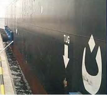
8.3.3.6.3
The marks of minimum safety working loads (SWLs) of fairleads and tugging bitts (§3.6.8)
fairleads and tugging bitts are to be clearly marked by bead weld outline with its
SWL, expressed in tonnes (letter “t”), in accordance with the Table below:
SWLs for bitts
|
Ship size in DWT
|
Maximum rope loading in tonnes - attached with Eye
(Figure-of-Eight belayed)
|
Nominal size of bitt in mm
|
|
16,000- 50,000
|
64 (32)
|
400
|
|
Above 50,000
|
92 (46)
|
500
|
8.3.3.6.4 The
pick-up rope for pulling the tug close to the vessel. (§3.6.6)
8.3.3.6.5 Verify The
test certificates or equivalent statement of mooring lines.
Anchoring
and mooring equipment
8.3.4.1 Design of mooring equipment
(1) Reasons
for the design of mooring equipment: The most common terminals for tankers are
piers or sea islands. Insufficient or inadequate moorings may cause unlimited
movement or the broken lines at the mooring site, make the ship to drift away
from her proper position, result in fire or explosion of the ship or terminal,
injuries of persons and damage to terminal facilities and ships. (§4.1.1, 4.1.4)
(2) Intention
for the design of mooring equipment: to establish safe mooring between ship and
terminal to prevent the ship from drifting away from a terminal and hold the
ship in place which may only have limited freedom of movement. (§4.1.4)
(3) The
mooring system of a ship must resist the forces due to one or more of the
following factors: wind, current, tides, surges from passing ships, waves and
swell, change of draft and freeboard, and ice. (§4.1.4)
(4) For
all ships above 16,000 tonnes deadweight intended for general worldwide
trading, the mooring restraint available onboard the ship as permanent
equipment are to be, according to the requirements of oil industry
organizations, sufficient to satisfy the following conditions: (§4.1.5)
.1 60 knots wind (Beaufort scale 11) from
any direction simultaneously with:
.2 3 knots current at 0o or 180o; or
.3 2 knots current at 10o or 170o; or
.4 0.75 knots current from the direction of
maximum beam current loading.
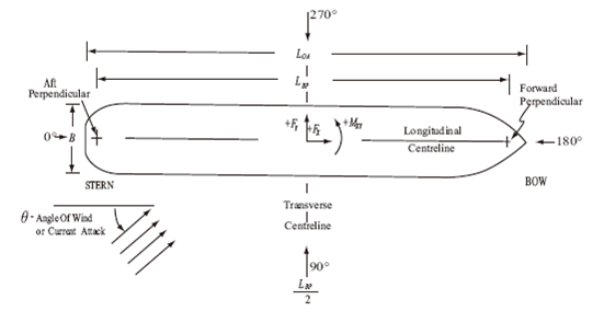
Single and integrated mooring arrangement
for ships
(5) Mooring
equipments for tankers are to be in accordance with the Mooring Equipment
Guidelines and the Effective Mooring. Exxon Moil requires that its Marine
Environmental, Safety and Quality Assurance Criteria is to be complied with, in
addition to the Mooring Equipment Guidelines and the Effective Mooring. (§4.1.7, 4.1.9)
(6) Mooring
equipment are to be designed according to recognized standards or the
approximate methods given in Appendices A, B, C & D of Guidelines of Oil
Organizations for Structure and Equipment of Tanker for determining the
strength of mooring equipment, e.g. lines, winches, bollards and fairleads
provided in the Mooring Equipment Guidelines. (§4.1.8)
(7) For mooring of
tankers of normal sizes at piers or sea islands, the mooring equipment are to
be designed to be capable of withstanding loads not less than that given in the
Table below, corresponding to ship sizes. (§4.1.6)
|
Ship size (DWT)
|
Transverse forces (tonnes)
|
Longitudinal forces (tonnes)
|
|
Wind
|
Current
|
Wind
|
Current
|
|
18000
|
Loaded
|
33
|
16
|
17
|
6
|
|
Ballast
|
84
|
9
|
21
|
4
|
|
30000
|
Loaded
|
50
|
42
|
23
|
16
|
|
Ballast
|
112
|
21
|
26
|
9
|
|
70000
|
Loaded
|
67
|
78
|
25
|
30
|
|
Ballast
|
168
|
21
|
34
|
18
|
|
150000
|
Loaded
|
98
|
107
|
34
|
42
|
|
Ballast
|
213
|
29
|
46
|
23
|
|
300000
|
Loaded
|
156
|
171
|
51
|
67
|
|
Ballast
|
336
|
48
|
72
|
25
|
|
LNG
Carrier
|
125000 m3
|
396
|
76
|
78
|
30
|
(8)Based on a
standard environmental condition that is representative of common piers or sea
islands called by ships engaged in worldwide trades, a typical mooring pattern
at a tanker terminal is shown in the figure below: (§4.1.1)
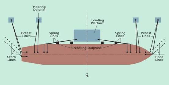
Typical mooring pattern at a tanker
terminal
(9) In situations
where the standard environmental criteria are likely to be exceeded due to worse
conditions in some exposed piers or sea islands, the existing mooring
capability of ships calling at such terminals may be insufficient and are to be
supplemented by mooring equipment on shore. (§4.1.3)
8.3.4.2
General
arrangements of mooring equipment
(1)
Mooring
equipment is to be satisfied for minimum number of mooring lines. (§4.2.1)
(2)
In the
bow area (from accommodation space to bow mooring station), at least 5 closed
fairleads, 3 bollards and in total 8 head lines are to be provided on each side
of the ship. (§4.2.2)
(3)
In the
stern area (from accommodation space to stern mooring station), at least 4
closed fairleads, 2 bollards and in total 6 stern lines are to be provided on
each side of the ship. (§4.2.3)
(4)
At
least two closed fairleads are to be located within 35 m forward and aft of the centre of the cargo
manifold with associated mooring bollards and lead to winches, especially
during ship to ship transfer operations. (§4.2.5)
(5)
For
vessels whose freeboard exceeds 16.5
m, closed fairleads are to be fitted within 10 m fore and after of the cargo
manifolds. (§4.2.6)
(6)
During
ship to ship transfer operations, sufficient number of closed fairleads is to
be provided for all lines at bow, midship and stern depending on the sizes of
the ships. It is recommended that all the fairleads are of the closed type. (§4.2.7)
Refer to the figures below.
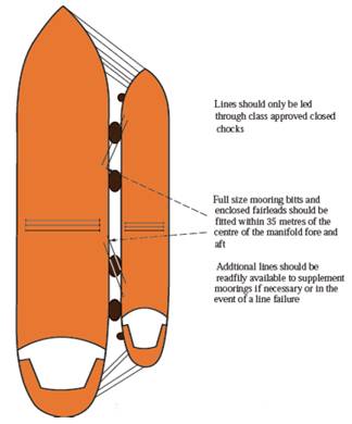
Mooring pattern during ship to ship
transfer

Ship to ship transfer mooring arrangement
(7) Arrangement requirements for gas carriers,
especially large LNG carriers are as below: (§4.2.8)
.1 For flush deck LNG and LPG carriers the
arrangement for spring lines and associated winches may be similar to those
adopted for oil and chemical tankers.
.2 For spherical tank LNG carriers and
lobe/cylindrical tank LPG carriers, it is usually not practicable to
incorporate main deck winches and the lead of springs must be from aft of the
accommodation deckhouse and from the forward main deck or the forecastle, as
per figures below.
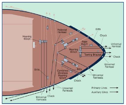
LNG carrier - mooring arrangement on the forward deck
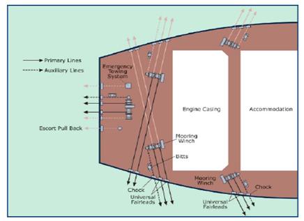
LNG carrier - mooring arrangement on the aft deck
(8) Mooring patterns corresponding to tanker type and size are shown as
follows:
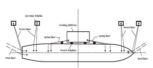
Mooring pattern at a tanker terminal
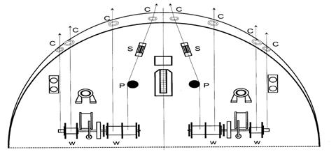
Anchoring and mooring arrangements
Winch (W); Closed fairlead (C); Bow chain
stopper(S); Pedestal roller lead (P)
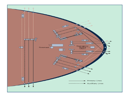
Oil and chemical tankers -
mooring arrangement on the forward deck
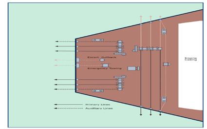
Oil
and chemical tankers - mooring arrangement on the aft deck
Mooring lines
8.3.4.3.1 Mooring
lines are to be in compliance with the following requirements:
(1) Size and construction of mooring lines are to comply with OCIMF
publication Mooring Equipment Guidelines and the requirements for tankers
mooring at piers or sea islands. (§4.3.1)
(2) Mooring lines other than single point
moorings are to comply with the requirements for the mooring of large tankers
at terminals. Recommendations on their use are contained in the OCIMF
publication — Guidelines on the Use of High Modulus Synthetic Fibre Ropes as
Mooring Lines on Large Tankers. (§4.3.3)
8.3.4.3.2 Materials of mooring lines
(1) Mooring lines may be made from steel,
synthetic fibres, low stretch ropes made from steel wire, high elastic mooring
lines made from synthetic materials such as High Modulus Polyethylene (HMPE) or
Aramid fibres. (§4.3.2)
(2) Polypropylene rope has approximately the
same elasticity as polyester rope. However, as sparks may arise on
polypropylene when subjected to break load, the use of tanker moorings
manufactured from polypropylene is not recommended by oil industry
organization. (§4.3.4)
(3) For tankers above 16,000 DWT, mooring
lines of low modulus material are recommended. (§4.3.20)
8.3.4.3.3
Constructions of mooring lines
(1) Mooring
wires may be of various constructions. Typical wire line constructions are as
follows: (§4.3.10)

Lefthand
Righthand Lefthand
Righthand

6
× 36 fibre core 6
× 36 steel core 6
× 41 steel core
Wire line constructions
(2)
Synthetic
mooring lines can be constructed in a variety of forms. The common structures
used in synthetic ropes are shown in the figure below: (§4.3.18)

Construction of conventional and high
modulus synthetic fibre ropes
8.3.4.3.4
Wire rope end terminator (§4.3.19)
Three types of wire rope end terminator are
normally used: swaged, spliced, and socketed. Splices in eyes are to have a
minimum of 5 tucks, as indicated in the figure below:
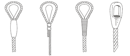
Swaged Swaged
Spliced
Poured
socket
Types
of wire rope terminations
8.3.4.3.5 Tails of
mooring lines
(1) The traditional tail (pendants) length of 11 m is adequate for sheltered pierside moorings. At
exposed pierside moorings where significant ship motions occur, the tail
(pendants) length of 11 m may be
inadequate. This could lead to immediate tensile failure, or in the longer
term, lead to the fatigue failure of main winch ropes and/or mooring equipment
on board or ashore. (§4.3.6)
(2) For mooring lines made from steel wires,
high modulus fibres are to be used for the manufacture of tails. (§4.3.5)
(3) Longer tail (pendants) lengths may be
required for the most harsh conditions, where waves up to 2 m significant wave height and having
periods in excess of 10 seconds may be encountered at exposed pierside.
Increased tail (pendants) length will typically only be required for breast
lines and may not be necessary for springs lines. (§4.3.7)
(4) Synthetic tails (pendants) for wire
mooring lines are to be replaced at least every 18 months unless experience,
hours in use coupled with inspection by inspectors professionally trained with
skilful assessment methods indicates a longer or shorter period is warranted. A
record of service is to be maintained that includes time in use and inspection
results. Tails are to be replaced prior to their residual strength falling to
60% of their original MBL. The 18 month period mentioned above is based upon
the actual time in use on an average ship in average trade. A tail
inspection/assessment program is to be in place (with records). The inspector
is to confirm that training for tail inspection/assessment has been effectively
carried out. (§4.3.11, 4.3.12)
8.3.4.3.6
Connection of mooring lines and tails
(1) Tails
are to be connected to a wire mooring line using appropriate shackles, for
example, those manufactured by Tonsberg or Mandal, as indicated by the figures
below: (§4.3.13)
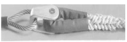
Synthetic tails connected to a wiring
mooring line using Tonsberg shackle
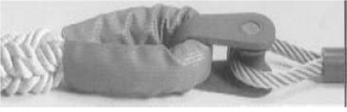
Synthetic tails connected to a wiring
mooring line using Mandal shackle
(2)
A
synthetic tail can be attached directly to a high modulus rope by using a cow
hitch, as indicated by the figure below: (§4.3.14)

(3)
Tails
may be connected to a wire mooring line using boss shackles, as indicated in
the figure below: (§4.3.15)

Boss shackle
8.3.4.3.7 Additional
provisions of mooring lines
(1) To ensure safe cargo operations, especially during ship to ship
transfer, a vessel is to be provided with four fibre ropes of minimum 20 mm diameter and 20 m length for hose handling at the manifold, and
with four synthetic messenger lines. (§4.3.16)
(2) Two steel wire lines are to be provided
forward and aft respectively, each a minimum of 100 m long × 30 mm diameter. (§4.3.17)
8.3.4.3.8
Minimum breaking loads (MBLs) of mooring lines
(1) MBLs
of mooring lines are closely related to the material and construction of lines.
Nominal MBLs for steel wire lines of 6 × 36 class are shown the Table below. (§4.3.21)
Typical size and MBLs of 6 × 36 class steel
wire mooring lines
|
Diameter
mm
|
Weight
Kg/100m
|
MBL
kN
|
|
24
|
236
|
402
|
|
26
|
276
|
472
|
|
28
|
321
|
547
|
|
30
|
368
|
628
|
|
32
|
419
|
715
|
|
36
|
530
|
904
|
|
40
|
654
|
1,120
|
|
44
|
792
|
1,350
|
|
48
|
942
|
1,610
|
|
52
|
1,110
|
1,800
|
|
56
|
1,280
|
2,190
|
|
60
|
1,70
|
2,510
|
|
64
|
1,700
|
2,800
|
|
68
|
1,900
|
3,100
|
|
72
|
2,200
|
3,500
|
|
76
|
2,400
|
3,800
|
|
80
|
2,700
|
4,200
|
(2)
Synthetic
tails are to have a MBL at least 125% that of the mooring line to which it is
attached. Polyamide tails are to have a MBL 137% that of the mooring line to
take account of loss of strength when wet. (§4.3.9)
8.3.4.3.9
Mooring retention capability requirements of mooring lines (§4.3.23)
(1) Vessels
below 46,000 DWT are to provide a mooring retention capability in accordance
with the Table below:
Mooring retention for tankers below 46,000
DWT
|
Vessel size(DWT)
|
Number of mooring lines
|
Mooring Retention (Tonnes)
|
|
Below 2000
|
6
|
90
|
|
2000~3000
|
6
|
105
|
|
3001~4000
|
6
|
125
|
|
4001~5000
|
6
|
150
|
|
5001~15000
|
8
|
220
|
|
15001~20000
|
10
|
320
|
|
20001~46000
|
10
|
360
|
(2)
Vessels
of 46,000 DWT and above are to provide a mooring retention capability in
accordance with the Table below:
Mooring retention for tankers of 46,000 DWT
and above
|
Vessel size(DWT)
|
Number of mooring lines
|
Breaking strength (tonnes)
|
Mooring Retention (Tonnes)
|
|
46000~75000
|
8
|
35
|
25
|
|
75001~100000
|
8
10
12
|
70
55
50
|
40
30
30
|
|
100001~140000
|
8
10
12
|
80
65
50
|
45
35
30
|
|
140001~160000
|
8
10
12
|
85
70
55
|
50
40
30
|
|
160001~250000
|
10
12
|
85
70
|
50
40
|
|
250001~400000
|
12
14
16
|
85
80
70
|
50
45
40
|
Bollards or bitts
8.3.4.4.1 Arrangement and installation of bollards
or bitts
(1) Bollards are to be adequate for the mooring capacity as required by
ship size and to be evenly fitted on each side of the ship. (§4.4.1)
(2) All
bollards/bitts are to be welded to the deck on each side of the ship in way of
the location required. (§4.4.2)
(3) Some high freeboard ships, such as LNG
carriers, may be provided with bollards in the vicinity of the ship’s side shell.
(§4.4.3)
(4) Double bollards of minimum 300 mm in diameter are to be fitted
forward and aft of the cargo manifold on each side of the ship. (§4.4.10)
(5) A cruciform bollard is to be fitted in
line, or nearly in line with the vapour return system manifold to allow
securing of the VRS hose hang-off chain. (§4.4.12)
(6) Two deck pad-eyes of size sufficient to
secure 16” cargo hose are to be
provided within the line from the closed chock to the vapour return system
manifold. (§4.4.13)
(7) Line stoppers are to be fitted in the
vicinity of each set of double bollards and each cruciform bollard. (§4.4.9)

Stoppers for bollards
(8) Spill tank end deck is to be provided with
cruciform bollards, which are to be so arranged that: (§3.3.7)
.1 the minimum spacing between
the bollard centre and the spill tank fore end is 1,200 mm;
.2 the minimum spacing between
the bollard centre and the spill tank side end is 300 mm;
.3 the
minimum length of the bollard is 400
mm.
(9) During ship to ship transfer operations,
the centre of the cargo manifold is to be located within 35 m forward and aft of the mid-length of the ship and
a bollard for breast line, two closed fairleads, two double bollards and winch
auxilary facility are provided at least. (§3.2.10)
(10)Bollards
are normally welded to the ship’ deck. (§4.6.12)
8.3.4.4.2
Categorization of bollards or bitts
(1) Bollards
may be categorized into single bollards, double bollards and cruciform bollards,
as shown in the figures below: (§4.4.4)
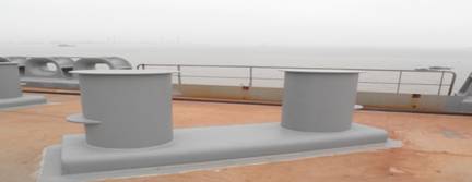
Double
bollards
Cruciform
bollards
(2)
Mooring
bitts fitted onboard a ship, including that used for emergency towing-off
wires, are to be double bollards. (§4.4.6)
(3) The diameter of double bollards is normally
not to be less than 10 times that of mooring lines, and at least greater than 300 mm. (§4.4.7)
(4) Double bollards can normally withstand
loads of lines that are twice that of a cruciform bollard. (§4.4.5)
(5) Sets of cruciform bollards, minimum 600 mm in height above deck are to be
fitted to the deck on each side of the ship in the vicinity of cargo manifold
centreline. The bollards are to be fitted on the deck mid-way between each pair
of cargo manifolds, allowing maximum wide access between the working platform
and ship’s side and giving sufficient space (about 300 mm) between bollard and spill tank to operate
safely. (§4.4.14)
Cruciform bollards in the vicinity of cargo
manifold centreline on deck
(6)
For
ships of 160,000 DWT and upwards, twin sets of bollards at least of 550 mm diameter are to be located
inboard of the closed fairleads for handling the moorings. (§3.3.9)
8.3.4.4.3 Safe working loads of bollards or
bitts
(1) The
Safe Working Load (SWL) marked on the bitts are to be the maximum allowed when
using a wire or rope belayed in a figure of eight near the base of the bitts.
The SWL is in no case to be less than the Minimum Breaking Load (MBL) of
mooring lines. According to the conventional design, the SWL is to be twice the
MBL of mooring lines. (§4.4.8)
(2) Cruciform bollards are of a minimum working
load of: (§4.4.11)
.1 25
tonnes for ships below 60,000 DWT;
.2 40 tonnes for ships of 60,000 DWT
and above.
Fairleads
8.3.4.5.1 Arrangment and installation of fairleads (pay
attention to Appendix C Reinforcements
of Mooring Equipment and Ship Structure of the Guidelines)
8.3.4.5.2 Categorization of fairleads
Fairleads can be categorized into open
fairleads, closed fairleads, panama-type fairleads, pedestal roller fairleads
and universal roller fairleads, as shown in the figures below: (§4.5.7)
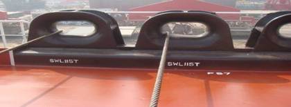
Closed fairlead marked with SWL
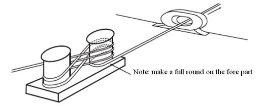
Closed fairlead
Closed roller fairleads
8.3.4.5.3 Fairleads
are to be in compliance with the following requirements:
(1) All fairleads fitted onboard tankers are to be of closed type. (§4.5.1)
(2) Only one line is allowed to pass through
each closed fairlead in order to ensure safe mooring. (§4.5.2)
(3) Clear openings of the fairleads are to be
at least 400 mm × 250 mm and the minimum radius of curvature is
to be 180 mm. (§4.5.3)
8.3.4.5.4
Working loads of fairleads
(1) The
working load of fairleads depends on the ship size and working conditions of
the machine. However, it is in no case to be less than the MBL of the line
passing through the fairlead. (§4.5.5)
(2) The
working load of fairleads during cargo operations is normally not to be less
than: (§4.5.6)
.1 25 tonnes for tankers below
60,000 DWT;
.2 40 tonnes for tankers of
60,000 DWT and above.
8.3.4.5.5
Tankers above 175,000 DWT are to be provided with lightening arrangements as
follows: (§4.5.8)
(1) Two additional sets of heavy duty closed
fairleads with clear openings of 500
mm × 400 mm
are to be positioned on each side of the ship (at least on starboard) within 35 m forward and aft of the mid-length of
the ship or as close to this position as possible.
(2) Double bollards of 550 mm diameter are to be located inboard of the fairleads.
(3) All other fairleads used during mooring
are to be of the closed type to avoid difficulties occurring owing to the large
relative changes of freeboard experienced during lightening operations. Quick
release mooring hooks are to be provided at terminals.
Quick release mooring hooks at a terminal
Winches
(For brake testing and performance standards of winches, refer to Appendix D
Mooring Winches of the Guidelines)
8.3.4.6.1 Arrangement and installation of winches (pay attention to Appendix C Reinforcements of Mooring Equipment and Ship
Structure of the Guidelines)
(1) The minimum distance between a fairlead
and bitts is to be 1.8 m. (§4.6.9)
(2) The minimum distance between a winch drum
and the nearest fairlead or chock is to be such that the fleet angle does not
exceed 1.5°. (§4.6.10)
(3) Mooring winches are normally bolted to
foundations that are welded to the ship’s deck. (§4.6.12)
8.3.4.6.2 Categorization of winches
(1) Winches may be categorized by their
control type into manual and automatic tensioning. (§4.6.1)
(2) Winches may be categorized by the type of
drums into split and undivided types. (§4.6.3)
(3) Automatic tension winches are designed to
automatically heave-in whenever the line tension falls below a pre-set value,
or pay out if the line tension exceeds a pre-set value. Tension winches are not
allowed to be operated in the automatic mode when the ship is connected to the
shore cargo manifold. (§4.6.2)
(4) Tension winches are not allowed to be
operated in the automatic mode when the ship is connected to the shore cargo
manifold. (§4.6.7)
8.3.4.6.3 According to a recognized standard, the SWL of
winches is to be greater than the line’s MBL. (§4.6.4)
8.3.4.6.4 Brakes of winches
(1) Winches are to be provided with brakes
which are normally divided into hydraulic brakes and manual brakes. (§4.6.11)
(2) Winch brakes are to be designed to hold
80% of the line’s MBL and have the capability to be adjusted down to 60% of the
line’s MBL, at which level they are to be set in service. (§4.6.5)
(3) The primary brake is to be set to hold
60% of the mooring line’s MBL. Since brakes may deteriorate in service, it is
recommended that new equipment be designed to hold 80% of the line’s MBL, but
have the capability to be adjusted down to 60% of the line’s MBL. (§4.6.6)
(4) Testing report of winch
brake holding capacity
8.3.4.6.5 Winch storage drums used to stow the rope are to
be capable of lifting at least 15 tonnes and be of sufficient size to
accommodate 150 m of 80 mm diameter rope. (§4.6.8, 4.8.3)
8.3.4.7Mooring
procedures and conditions of mooring equipment
1) Moorings
are satisfactorily arranged and mooring lines of the same size and type
(material) are used for all leads.
2) Mooring
lines are secured to bitts and turned up correctly.
3) All
powered mooring lines are correctly reeled on drums.
4) All
powered mooring lines are secured on brakes and the winches are to be out of
gear.
5) On split
drum winches, all the lines are made fast with no more than one layer on each
tension side of the drum.
6) Tails are
connected to a wire mooring line using appropriate shackles, for example, those
manufactured by Mandal, Tonsberg, and be correctly fitted.
7) All
mooring lines are stowed neatly to minimise tripping hazards and mooring areas
are to be clear and unobstructed.
8) Winch
brakes are on.
9) Winches
are in good order.
10) Winch
foundations are in good order.
11) Brake
linings, drums and pins are in good order.
12) If
mooring winches in a gas hazardous area are electrically powered, motors are EX
‘d’ rated.
13) If
mooring winches are electrically powered, insulation tests are carried out and
the results recorded.
14) For
steam winches, the steam chest and its joint seat to the winch are in good
order without corrosion or temporary repair.
15) Mooring
wires, ropes and synthetic tails are in good order.
16) Pedestal
fairleads, roller fairleads and other rollers are well greased and free to turn
and bitts and chocks are to be free of grooving.
17) Mooring
equipment is marked with its SWL.
18)
Insulation resistance of electrical equipment is at least 5 Megohm.
19) Mooring
lines have sufficient strength, i.e., the reduction of strength is not greater
than 10% of the minimum breaking load (MBL). Splices in eyes and for repairs
have a minimum of 5 tucks. There are not more than three broken wires in any
strand, or five in any adjacent strands in a length of wire 10 times the
diameter.
Single
point mooring (SPM)
8.3.4.8.1
Arrangment of SPM
(1) For
ships likely to be moored at single point moorings, SPM equipment is to be
equipped according to ship size. (§4.7.1)
(2) Existing
ships delivered before 2009 likely to visit SPMs are to be so equipped that the
number of pedestal rollers used for each bow chain stopper is not to exceed one
and the angle of change of direction of the pick-up rope lead is to be
minimized. SPM equipment, including fairleads, chain stoppers, pedestal rollers
and winches, are to be arranged in line as far as possible. If not possible,
they are to be so arranged that the angle of change of direction is not to
exceed one. A vertical angle is not allowed. The inspector will normally accept
the angle not less than 120° or sometimes require not less than 150°. (§4.8.7)
(3) For
new ships delivered during or after 2009 likely to visit SPMs, wherever
possible, it is recommended that winch storage drums used to recover the
pick-up ropes are positioned in a direct straight lead with the bow fairlead
and bow chain stopper without the use of pedestal rollers. This relative
positioning of the tanker SPM mooring equipment in a direct straight lead is
considered the safest and most efficient arrangement for handling the pick-up
ropes. However, recognising that not all new mooring arrangement designs will
permit direct straight leads to a winch storage drum, consideration of safety
and protection from risk of whiplash injury to mooring personnel is to take
priority in determining number and positioning of pedestal rollers. (§4.8.1)
(4) Remote
operated winch storage drums may afford some additional whiplash injury
protection for the winch operator. (§4.8.2)
(5) Use
of winch drum ends is to be avoided, and therefore a separate winch is to be
provided for single point mooring. (§4.8.3)
(6) Fairleads
for SPM and their arrangement (§4.8.4)
.1 For ships fitted with only one SPM
equipment, the fairlead is to be on the centre line.
.2 For ships fitted with two SPM
equipment, the fairleads are to be spaced 2.0 m
centre-to-centre apart, if practicable, and in no case to be more than 3.0 m apart.
.3 All bow fairleads are to be
measure at least 600 mm
× 450 mm.
(7) Stoppers
for SPM and their arrangement (§4.8.5)
.1 The stoppers are to be
permanently marked with the mooring capability and provided with valid
certificates.
.2 Bow
chain stoppers are to be located between 2.7 and 3.7 m inboard from the bow fairlead regardless of ship
size.
.3 Pedestal rollers are to be
provided according to the arrangement of winches.
.4 Pick-up rope is in no case to
pass through more than one winch with pedestal roller.
.5 There are to be at least 4.5 m distance between the bow chain
stopper and the closest pedestal roller, if fitted.
(8) Size and provision of winches for SPM (§4.8.6)
.1 Winches may be used in
conjunction with anchors, or independently. Winch storage drums used to stow
the pick-up rope are to be of sufficient size to accommodate 150 m of 80 mm diameter rope.
.2 The SPM equipment including
stoppers, pedestal rollers (if fitted), winch foundations and supporting deck
structure are to be adequately reinforced.
.3 The capacity and arrangement
of SPM equipment are to be in compliance with Appendix A of OCIMF publication
Mooring Equipment Guidelines.
.4 Each bow chain stopper for
SPM is to be provided with one winch capable of lifting at least 15 tonnes. (§4.7.6)
(9) Ships
mooring to an SPM are to be provided with fittings on the stern for tug escort
and pull-back duties, as shown in the figure below. (§4.8.8)
Fittings for tug escort and pull-back at
SPM
.1 Chock/fairlead
and strong point
① For tankers over 20,000 DWT but under
50,000 DWT, the chock arrangement is to have a minimum SWL of 100 t. The strong
point arrangement is also to have a minimum SWL of 100 t when used with a
single eye towing line or grommet.
② For tankers of 50,000 DWT and above, the
chock arrangement is to have a minimum SWL of 200 t. The strong point
arrangement, with suitable reinforcement, is also to have a minimum SWL of 200
t when used with a single eye towing line or grommet.
.2 The safety factor of major
components for tug escort and pull-buck is to be of 2 times the SWL rating.
.3 The chock/fairlead is to be
located on the stern, as close as possible to the centreline of the ship. The
chock opening is to be oval.
.4 The strong point or
connection point is to be aligned longitudinally with the chock and clear of
all obstructions.
.5 The strong point is to have a
minimum diameter of 600 mm
and a minimum height of 300 mm
above deck.
.6 The minimum distance from
strong point to chock is to be 4.0 m.
Considering that this may be difficult to achieve on ships of less than 50,000
DWT, the distance from strong point to chock may be less than 4.0 m provided that it is ensured that
the eye splice of the towing line sits inboard of the chock.
.7
Each Fitting for tug escort and pull-back is to be clearly marked with its SWL.
Note:
The SWL is to be expressed in tonnes (letter “t”) and other means of expression
is not accepted.
.8 Fixed gear for tug escort and
pull-back such as strong points, chocks, foundations and associated supporting
structure are to be demonstrated as adequate for the loads imposed.
(10)
Ship owners may require that the emergency towing arrangements (ETA) fitted at
both ends onboard tankers as required by SOLAS II-1/3-4 are to be suitable for
escort/pull-back duties while mooring to an SPM. In order to provide this dual
purpose capability, escort/pull-back and SPM requirements are to be complied
with while designing the emergency towing arrangement. (§4.8.9)
(11)
Some oil companies such as Chevron, BP and STASCO require a higher standard for
SPM equipment, that is, for tankers of 100,000 DWT two sets of SPM equipment
are required to be fitted. (§4.7.9)
(12)
See figures below for drawings of the typical arrangements of SPM equipment. (§4.7.7)

SPM
arrangement
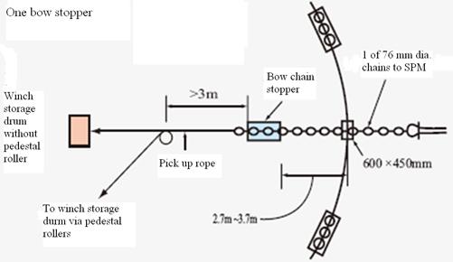
SPM
arrangement - one bow chain stopper
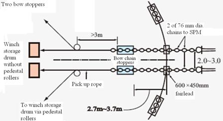
SPM
arrangement - two bow chain stoppers
(13)
Single point mooring and conventional mooring modes are shown in figures below:
(4.7.10)

A
single point mooring

A
conventional buoy mooring
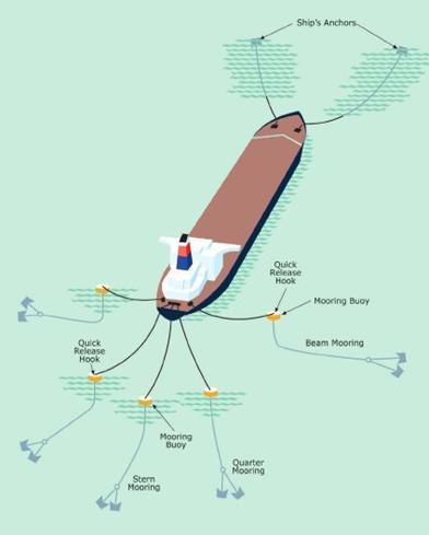
Multi-buoy
mooring

ULCC
buoy mooring arrangement
(14)
Inspecting the installation of SPM winches, bow chain stoppers, fairleads and
chafe chains. Pay attention to Appendix C Reinforcements of Mooring Equipment and Ship Structure of the Guidelines.
8.3.4.8.2 SPM equipment is to comply with the
following requirements:
(1) New ships delivered during or after 2009 likely to visit SPMs are to be
equipped with bow chain stoppers designed in accordance with the following: (§4.7.2)
.1 up to 100,000 DWT: 1 stopper
200 tonnes SWL;
.2 100,000 to 175,000 DWT: 2
stoppers 250 tonnes SWL;
.3 over
175,000 DWT: 2 stoppers 350 tonnes SWL.
(2)
Owners
of ships under construction before 2009 are encouraged to consider fitting bow
chain stoppers in accordance with the recommendations for new ships as far as
reasonable and practical. However, the bow chain stoppers equipped according to
the previous requirements are also accepted. (§4.7.3)
(3)
If the
vessel is fitted with a hydraulically operated bow chain stopper, safeguards
are to be provided to prevent its accidental release. (§4.7.4)
(4)
Bow
chain stoppers equipped on ships likely to visit SPMS are to be designed to
accept 76 mm chafe
chain. (§4.7.5)
(5)
Size,
quantity and type of stoppers are to be determined corresponding to the ship
sizes categorized in the OCIMF guidelines. (§4.7.8)
8.3.4.8.3 If the vessel is fitted with a hydraulically
operated bow stopper, safeguards are provided to prevent its accidental release.
8.3.4.8.4 SPM and associated equipment are in good order.
8.3.4.8.5 Chain stopper foundations are in good order.
8.3.4.8.6 The winch storage drum is of
sufficient size for storage.
8.3.4.8.7 The arrangements at stern for tug
escort and pull-back is in good condition.
Emergency towing arrangements
8.3.4.9.1 Installation of emergency towing winches, chain
stoppers, fairleads and chafe chains
8.3.4.9.2 The forward and aft emergency towing arrangements
are readily available for deployment.
8.3.4.9.3 The strong point foundation is in good
condition.
8.3.4.9.4 Procedures for deployment of emergency
towing arrangements or emergency towing procedures.
8.3.4.9.5 Arrangement of emergency towing
arrangements is posted on the navigation bridge.
8.3.4.9.6 Emergency towing arrangements are marked
permanently with SWL.
8.3.4.10 Emergency
towing-off pennants (fire-wires)
(1) The arrangement of
emergency towing-off pennants (fire-wires) is to be in compliance with the
requirements of the port State Administration and specifications of OCIMF on
the size and provisions of ships. (§4.9.1, 4.9.2)
(2) The construction and
material of emergency towing-off pennants (fire-wires) are to be in compliance
with OCIMF requirements. (§4.9.2)
(3) The minimum length
and strength of emergency towing-off pennants (fire-wires) (§4.9.3)
(4) The emergency
towing-off pennants (fire-wires) are to be readily available. (§4.9.1)
(5) The diagram showing
the arrangement of emergency towing-off pennants (fire-wires) are to be displayed
in the wheelhouse. (§4.9.2)
8.3.4.11
Ship to ship (STS) transfer requirements and operational manuals
(1)
It is
recommended that all fairleads used during STS transfer operations are of an
enclosed type.
(2)
Such
fairleads are to be strong enough to take the anticipated mooring loads and
large enough to allow the mooring line (plus any soft rope and shackle) to pass
through comfortably. (STS Guidelines 9.3)
(3) Full
strength enclosed fairleads and bitts for spring lines need to be positioned no
more than 35 metres forward and aft of the cargo manifold. (STS Guidelines 9.3)
(4) It
is recommended that all tankers be fitted with an array of mooring bitts of
sufficient strength on each side of the ship. (STS Guidelines 9.3)
(5) In addition it is recommended that
provision be made for securing fender lines. (STS Guidelines 9.3)
(6) For liquefied gas carriers, refer to the
recommendations in STS Guide (liquefied gas) of OCIMF/ICS.
8.3.4.12.1To inspect that the installation and arrangement
of windlasses is in compliance with the plan requirements (pay attention to
Appendix C Reinforcements of Mooring
Equipment and Ship Structure of the Guidelines)
8.3.4.12.2 To confirm
SWL marks.
8.3.4.12.3 To test the
braking load of windlass according to the instruction booklet.
8.3.4.12.4 Windlasses, anchors, locking bars and
cables are in good condition and operate effectively.
8.3.4.12.5 Anchoring equipment in use is locked
and windlasses not in use are secured by brake.
8.3.4.12.6 Bitter end securing arrangements are unobstructed
and outside the chain locker.
8.3.4.12.7 The chain locker doors are securely
battened down.
8.3.4.12.8 The foundation of chain stopper is in
good condition.
Prevention of pollution from ships
8.3.5.1 Vessel response plan
It
is to be noted that the Shipboard Oil Pollution Emergency Plan (SOPEP) or Shipboard
Marine Pollution Emergency Plan (SMPEP) and Emergency Response Plan (ERS) are
to be written in the working language of the ship, i.e., English.
Cargo operations and deck area pollution prevention
8.3.5.2.1 Continuous and transverse deck edge fishplates
are to be fitted on the tanker. Inspect the arrangements and heights of the
fishplates meet the requirements. (§5.2.1-5.2.3)
(1) Means are to be provided to keep deck
spills away from the accommodation and service areas. This may be accomplished
by means of a permanent continuous coaming of a height of at least 300mm, extending from side to side. Special
consideration is to be given to the arrangements associated with stern loading.
(2) Some oil companies such as
Exxon Mobil, requires the continuous coaming height of deck edge in the rear of
cargo area is to be:
I. For oil tanker and chemical tanker of more than 100,000 DWT, height of port and stbd. side permanent continuous coaming of fore deck
edge is to be transiting gradually from at least 250mm in bow to the rear of cargo holds
and connecting to Aft. athwartships coamings, of which the height is to be 400mm.
II.
For oil tanker and chemical tanker of less than 100,000 DWT, port and stbd.
side permanent continuous coaming of fore deck is to be transiting gradually
from at least 150mm
in bow to the rear of cargo holds and connecting to Aft. athwartships coamings,
of which the height is to be 300mm
(3) A secondary purpose of this coaming is to
provide oil retention at the after end of the maindeck in the event of an oil
spill, giving the crew sufficient time to deal with it and avoid oil entering
the water.
8.3.5.2.2
Scuppers are to be fitted on the deck edge.
(1) A
sufficient number of scuppers of suitable size are to be fitted in the
continuous deck edge fishplate. The capacity of the scupper is to comply with
the requirements of International Convention on Load Lines (LLC). (§5.2.3)
(2) Scupper
plugs of the mechanical type or equally effective means on the deck edge are to
be provided. (§5.2.5)
Scuppers
on gas carriers will only be required to be plugged when bunkering or if
carrying a MARPOL Annex 1 cargo.
8.3.5.2.3
Oil retention is formed on the deck by means of deck edge continuous fishplate
and transverse fishplate and means are to be provided for removal or disposal
of any spillage. Spilled oil is to be transferred to the slop tank by means of
fixed transfer system. Where portable spill transfer pumps are provided, the
piping is to be of the fixed type and the safe operation procedures are also to
be provided. However, the following matters are to be noted: (§5.2.4, 5.2.7)
(1) Non-sparking
spill transfer pumps are to be used and properly installed. (§5.2.7(1))
Portable
spill transfer pumps are also to be properly installed to prevent movement and
subsequent damage during operation.
(2) Inspect
the related bondings to prevent static electricity. (§5.2.7(1))
For
example: portable spill pumps are to be bonded to the vessel’s structure to
prevent electrical discharge to earth. Bonding may be made by external means,
or by the discharge hose, if this is attached by means of a flanged connection
to the vessel’s structure.
(1)
Where
portable spill pumps are provided and the discharge is led to a cargo tank,
there is to be a suitable fixed connection. Disposal of a spill is not to require
the insertion of the spill pump discharge hose through a tank opening such as a
sighting port.
(2)
Arrangement
of deck dump valves transferring the spilled oil to the slop tank and U-bends:
.1 For ships with
inert gas, circular sealing arrangement is to be provided for the deck dump
valve transferring the spilled oil to the slop tank. Generally speaking, the
majority of ships use U-bends. (§5.2.7(2))
l Where dump valves are installed at the
after end of the main deck, ascertain whether opening the valves will actually
result in the disposal of spilled oil to the tank. Excessive cargo tank vapour
pressure can result in a release of pressure when the dump valve is opened,
thereby aggravating the situation. Appropriate preventive measures are to be
taken.
l U-bends fitted in the dumping line to the
tank may allow spills to be safely disposed of without first having to
depressurise the tank, but this depends on the liquid level in the U-bend being
adequate to prevent back-flow of vapour.
.2 For ships not with inert gas, dump valve
may be used to transfer the deck spilled oil to the slop tank. The drain in the
slop tank is to be extended to the bottom of the tank in order to prevent
generation of static electricity (mist). (§5.2.7(3))
(3)
Matters
to be paid attention to during spilled oil transferring to the slop tank:
.1 The ullage of the
cargo in the tank may also affect the ability to drain spills from the deck,
particularly when the tank is full and the vessel is trimmed by the stern. If
spills can’t be drained effectively or pressure release need to be carried out
beforehand, the means of drain spills immediately are to be provided.
.2 It is to be
recognised that if the vessel is sagged then a spill will accumulate amidships
and if trimmed by the head then it will accumulate forward. The positioning of
spill equipment and disposal equipment must take these conditions into account.
8.3.5.2.4
If the use of a slop tank is not a viable option for some small ships, the deck
tank with a capacity of at least 2 m3 is to be available for collecting the spilled oil from
the deck. The deck tanks are usually used in chemical tanker. (§5.2.7(8))
Note: Deck tanks are to be of the fixed type.
8.3.5.2.5
To inspect the volume and size of the following spill containers or spill tanks: for the regulations in this aspect,
different organizations and port states have different requirements; if ship sails
in the waters of the United States, it is also to pay attention to the
requirements of Part 155.310, US 33 CFR. A higher standard is to be used.
(1) Spill
tanks are to be of the fixed type and provided with effective means for immediate
drainage and removal of spills.
(2) Requirements
for the sizes of spill tanks fitted below the flanges of cargo, bunker and
vapour return manifolds are as follows: (§5.2.8)
l Length: The spill tank is to extend along
the length of the ship, including the forward and aft ends of centres of the
presentation flanges of the cargo and bunker manifolds. On ships provided with
vapour return system, the forward and aft ends of centres of the presentation
flanges of the vapour return manifold are to be included.
l Width: The spill tank is to have a width of
approximately 1.8 m and is
to be so positioned that about 1.2 m
outboard of the reducer presentation flanges.
l Depth: The
spill tank is to have a minimum depth of about 300 mm.
l Vertical positioning: The working platform
is to be situated 900 mm below
the level of the centres of reducer presentation flanges.
(2)
At the
deck outlets of the vent pipes of all fuel tanks, fuel oil service, settling,
storage and lubrication oil tanks and other tanks containing flammable fluids, the
depth of spill tank is not to be less than 300
mm, but not to reach the opening of vent pipe (air pipe).
Generally the spill tank is to be located at least 200 mm below the opening. (§5.2.9-5.2.12)
Capacity:
(1) For ship of more than
75,000 DWT (Aframax), the spill containers are to have at least one barrel
(about 0.15m3),
(2) For ship of less than 75,000 DWT, the spill containers are to have at least
0.5 barrel (about 0.075m3).
Around
all hydraulic machinery, heating coils and other deck machinery on the deck,
the height of spill container is usually not to be less than 150 mm. (§5.2.14)
8.3.5.2.6 Adequate
fixed arrangements for the disposal of oily water are to be provided in the
forecastle and other spaces. (§5.2.18)
8.3.5.2.7 To check whether the switch for the engine room
oily water separator is on the navigation bridge. Such design prevents the
separator from starting due to inadvertent operation in special areas specified
by the ports and MARPOL or without approval from the officer of the watch.
8.3.5.2.8 In
addition to fuel oil tanks protected by double hull required by MARPOL Annex I 12A, EXXONMOBIL strongly recommends that
tanks carrying fuel oil, lubricating oil or other pollutants be protected by
double hull.
8.3.5.2.9 To check emergency stopping devices for sludge
and bilge water transfer pumps through the locations of shore connections for
discharging sludge or bilge water to shore (including bilge water transfer in
the engine and pump rooms). For pump room bilge water transfer, the stopping
device is to be at least operational from the upper deck (inside pump room).
8.3.5.2.10 To confirm the hydraulic hoses on the deck are
changed every five years. The Company is to have corresponding systematic
documents for inspection, test and replacement.
Arrangements for prevention of pollution from cargo
8.3.5.3.1 Appropriate numbers of dipping gauges are
to be provided in the aft part of every cargo tank to check the effectiveness
of cargo tank cleaning. (§5.3.2)
8.3.5.3.2 For all ballast tanks adjacent to the cargo tank,
sampling and observation devices are to be fitted on the weather deck. Inspect
that the arrangement and size of sampling and observation devices meet the
requirements. (§5.3.2, 5.4.5)
Note:
For gas carriers, only oil pipelines pass though the ballast tanks or the
ballast tanks are adjacent to bunker tanks, sampling and visual check of the
ballast tanks are required.
8.3.5.3.3 For ships which are to carry additional ballast
water in cargo tanks, the following requirements are to be complied with:
(§5.3.6)
(1) Ballast water is to be filled over the
top by means of dedicated ballast pumping and piping system and auxiliary
arrangements. The filling pipe of OVER THE TOP system is
to be extended to the bottom of the tank.
(2) The means of physical isolation is to be
taken for ballast and cargo systems. Normally 2 isolation valves are to be
taken for the above mentioned means of isolation, one stop valve and one
non-return valve, and the non-return valve is to be fitted in the side of the
cargo tank. Procedures for regular pressure checking and test are to be
provided for the means of isolation. The results of the test are to be recorded
and kept onboard the ship. Blank flanges or removable spool pieces are
normally used for physical isolation.
8.3.5.3.4 Means for removal of the spilled oil are to be
ready for use. (§5.3.7, 5.3.8)
Ballast water management
8.3.5.4.1 It is to be
noted that Ballast Water Management Plan is to be written in both English and Chinese.
(§5.4.1)
Pollution prevention equipment in engine and
steering compartments
8.3.5.5.1 The valves provided in the discharge outlet
of bilge system in accordance with SOLAS II-1/35-1 are to be closed under
normal conditions (without damage of hull and equipment) and sealed with
numbers. A specific warning notice read that “This valve is prohibited to be
opened without permission” is to be posted. (§5.6.3, 5.6.4)
8.3.5.5.2 Where
the emergency bilge suction valve is provided in machinery space, such valve is
to be closed and sealed under normal conditions and marked with the specific
warning notice read that “This valve is prohibited to be opened without
permission”. (§5.6.6)
During
the inspection, pay attention to the following points:
(1) SOLAS states that sanitary, ballast and
general service pumps may be accepted as independent power bilge pumps where
fitted with the necessary connections to the bilge pumping system. Although not
specifically described as such, this SOLAS requirement is to permit bilges to
be discharged overboard in an emergency situation and MARPOL Annex I Reg. 4
above, allows for this.
(2) The emergency bilge overboard discharge
must not be used for the disposal of daily machinery space bilge accumulations.
(3) Inspection of the ship’s side valve and
associated overboard pipework is to be carried out for evidence of oil contamination.
(4) In addition to the SOLAS requirement for
two means of disposing of bilges, there is a class requirement for an
additional emergency bilge disposal system and this will utilise a sea water
pump and will discharge directly overboard. This emergency bilge suction valve is
to be readily accessible and clearly marked as to its purpose. The means by
which operation of the emergency overboard valve is controlled to prevent
unauthorised discharge of oil or oily mixtures are to be determined. Positive
evidence that the overboard discharge valve has not been opened can be provided
by use of a numbered seal, the number of which can be verified in official
documents such as the Engine Room Log or the Oil Record Book Part I. Such a
method of sealing must be easily breakable to allow the valve to be opened in
an emergency.
(5) If
the vessel has an ejector as a substitute for one of the bilge pumps then it
may be necessary to ensure that the suction valves are similarly sealed.
8.3.5.5.3 Bilge water high-water-level alarm is to be
provided in the machinery space. It is suggested that the bilge pump of the
bilge system provided in accordance with SOLAS II-1/35-1 not initiated by the
high-water-level alarm. (§5.6.7)
8.3.5.5.4 Sludge pumps are to be free from any connection
to a direct overboard discharge, other than the standard discharge connection
to a deck discharge. (§5.6.10)
8.3.5.6To inspect
machinery space bilge auxiliary discharge system: to be approved by the
classification society.
(1) The oily water of
machinery space is to be discharged into the slop tank in special
circumstances. Where the ship is not in voyage or in the event of temporary
failure of the means for disposal of bilge water, the oily water or sludge from
engine room is to be discharged by means of the auxiliary discharge system for
emergency discharge.
(2) To check the
arrangement and installation of machinery space bilge auxiliary discharge
system according to the plans. (§5.7.1)
(3) Procedures for
operation of machinery space bilge water auxiliary discharge system are to be
provided. (§5.7.4)
(4) To inspect the
system for possible fire and pollution: refer to 5.7.3 of the Guidelines for
detailed technical requirements. (§5.7.3)
8.3.5.7
To
inspect the emergency handling means for oily water accumulated on the bottom
of pump-room. (ISGOTT 10.11.2)
On some tankers, no provision is made
for effective line draining and, in order to meet the demands of certain
product trades, final line contents are drained to the pumproom bilge. This is
an unsafe practice and it is recommended that cargo procedures be reviewed with
the aim of preventing flammable gases and volatile products being drained to
the bilge. Where lines that have been used for ballast have to be
drained to the pumproom bilge on completion of deballasting, care must be taken
to ensure that such drainings do not contain petroleum.
8.3.5.8
Garbage management
8.3.5.8.1 The
storage locations for garbage is to be carefully selected to ensure that the
garbage presents no potential hazard to adjacent spaces:
Particular
consideration is to be given to the storage of garbage that is designated as
“special waste”, such as batteries, sensors and fluorescent tubes, to ensure
that only compatible materials are stowed together. The ICS publication Guidelines
for the Preparation of Garbage Management Plans provides information on how to
comply with Annex V of MARPOL 73/78. (ISGOTT 12.4.2)
8.3.5.9
Control of other pollution
Mainly refer
to the following requirements for the control of special pollution required by
the related flag States and the Administrations of port States, such as:
(1)
EU’s
special requirements on low sulphur fuel oil for ships harbouring in its
terminals;
(2)
Requirements on noise grades, etc.
Prevention of fire and explosion
Control of flammable gas — prevention of excessive
accumulation of flammable gas
8.3.6.1.1 Inert gas system: the inspection
requirements are the same as those of FSS Code, but the provision requirements
are higher than those of FSS Code.
(1) Provision requirements (§6.1.1, 6.1.2, 6.1.3)
.1 Fixed inert gas system is to be provided
in cargo tanks when carrying cargoes with a flashpoint not exceeding 60℃ or when cargoes with a flashpoint
exceeding 60℃ are
carried at a cargo temperature higher than their flashpoint less 10℃.
.2 Ventilating systems interlocked with the
tank washing machine are to be provided in cargo tanks without fitting with
inert gas system to keep effective and continuous ventilation during tank
washing when carrying cargoes with a flashpoint below 60℃ or when cargoes with a flashpoint exceeding 60℃ are carried at a cargo temperature higher
than their flashpoint less 10℃.
.3 Fixed inert gas system is to be provided
in cargo tanks carrying cargoes with a flashpoint exceeding 60℃ when individual tank washing machines
have a throughput greater than 60 m3/h
or the total water throughput per cargo tank exceed 180 m3/h.
(2) Special
requirements:
.1 Fixed flammable gas detection systems are to be provided in the venting
systems of all double hull ballast tanks for ships fitted with fixed inert gas
system. Charging pipes of fixed inert gas system and air purging arrangements
are to be provided in double hull ballast spaces. And pipes for inert gas
supply for the double hull ballast space are to be provided on the deck of
cargo area. (§6.2.1(3),
6.2.2, 6.5.6)
.2 For cargo tank not fitted with inert gas
system, earthing or bonding or other effective measures are to be taken to
prevent static electricity for all the equipment in cargo tank, such as level sounding
device, sampling device and temperature gauge. Earthing and bonding are to be
achieved by means of connection between conductors with metal materials. (§6.3.2)
.3 Fixed tank washing system is not to be
provided in cargo tanks carrying cargoes with flash points not exceeding 60℃ if the inert gas system is not
provided. (§6.3.3)
8.3.6.1.2(1) Fixed flammable gas
detection systems are to be fitted to detect the concentration of flammable
gases in void space, ballast space or other spaces adjacent to cargo tank. (§6.1.4)
(2) Fire detection devices (thermal or smoke
sensitive) are to be fitted in the galley and sample storage room. (§6.5.2)
8.3.6.1.3 For ships fitted with the fixed inert gas system, two fixed and
portable oxygen-measuring equipment are to be provided. (§6.2.7)
Suppression
of ignition source
8.3.6.2.1 Reciprocating
main cargo pumps are forbidden to fit for cargoes with flash points not exceeding 60℃. And it is recommended not to use reciprocating
pumps as far as practicable for cargoes with flash points exceeding 60℃. (§6.3.1)
8.3.6.2.2 Smoking places:
Smoking
places are to be confined to locations within the accommodation. And smoking
places are not to have doors or ports that open directly onto open decks. Safety
matches or fixed (car type) electrical cigarette lighters are to be provided in
approved smoking locations. The use of all mechanical lighters and portable
lighters with electrical ignition sources is to be prohibited on board tankers.
(§6.3.8-6.3.10)
8.3.6.2.3 The use of portable stoves and cooking
appliances on board oil tankers is to be controlled. The use of portable stoves
and other cooking appliances that employ naked flames is to be prohibited
during cargo operation or when the ship is in port. (§6.3.6, 6.3.14)
8.3.6.2.4 The following equipment is to be of an intrinsically safe electrical equipment: (§6.3.11 -6.3.13)
l torches used in flammable
atmospheres; (§6.3.11)
l self-igniting lights of lifebuoys
in the cargo area; (§6.3.12)
l UHF/VHF walkie-talkie transceivers;
(§6.3.13)
l self-activating lights fitting on
lifebuoys in the cargo area are to be intrinsically safe
electrical equipment. (§8.13.4)
8.3.6.2.5 Window-typed air conditioning units are
prohibited.
Where such units are used in the existing ship,
their use is to be strictly controlled and prohibited during cargo operation or
when the ship is in port. (§6.3.13)
Window-typed air units are to be disconnected
during the following cargo operations:
l handling volatile petroleum or
non-volatile petroleum reaching or exceeding its flashpoint;
l filling non-volatile petroleum into
volatile hydrocarbon gas tanks;
l crude oil tank washing;
ballasting,
purging, gas-freeing or tank washing after discharging volatile petroleum
8.3.6.2.6
Moving parts of fire
fighting appliances such as nozzles, hose couplings are not to be made of
aluminium or aluminium alloy. (§6.3.16)
Fire-fighting
8.3.6.3.1 Appropriate fire blankets are to be readily available to galley
staff for emergency use. (§6.4.9)
8.3.6.3.2 Cargo samples are to be stored in places fitted with
fire-extinguishing system. (§6.4.10)
Cargo and ballast systems
Cargo and ballast systems (oil tankers)
8.3.7.1.1 Cargo
tanks:
(1) Each cargo tank is to be fitted with a high-level alarm and an independently
high-high-level alarm. In general, the setting of high level alarm is not to
exceed 95% of the tank capacity and that of high high level alarm not to exceed
98%. From the time a high-level alarm is sounded to the time the overfill
control device shuts down filling operation, the control is to be stable in
general. The duration generally is over 30 s but is not to exceed 1 min. (§7.1.1-7.1.3)
(2) Cargo
tanks carrying flammable and toxic liquid are generally fitted with closed-type
sounding devices. Vapour locks are to be provided if limited sounding devices
and sampling devices are fitted. In addition, at least two portable electronic
measuring instruments are to be provided onboard the ship. (§7.1.12)
8.3.7.1.2 Cargo system
(1) All
pipelines in cargo tanks are to be arranged as along to bulkheads as possible,
keeping a distance of not more than 300 mm from any structural members inside tanks,
unless special reliably earthed are taken. (§7.1.11)
(2) Details
of cargo pipelines:
l At least two pressure gauges are
to be fitted in the cargo system, one of which is to be fitted on the cargo
pipeline or the deck outside cargo pump room, the other on the outboard side of
the cargo manifold valve. (§7.2.1)
l Manifold valves are to be stop
valves or screw-down valves. Such valves are used to make the control as stable
as possible when the overfill control valve shuts down the filling operation so
as to reduce the sudden rise of pressure caused by the shutdown of the overfill
control valve. (§7.2.2)
l Manifolds are to be connected to
cargo hoses and cargo arms with flanges and manifold flanges fabricated of
steel. (§7.2.3)
(3) An
integrated cargo and ballast system are to be fitted to ensure the change of
air draft is stable in cargo operations so as to avoid excessive stresses on
the connections of cargo arms or cargo hoses to cargo manifolds. Such stresses
may even cause fracture and falloff, leading to pollution accidents. (§7.2.5)
(4) Emergency stops of main cargo
pumps are to be fitted in the cargo control room, at the upper pump room
entrance and near the manifold. (§7.2.7)
(5) When
there is a direct telephone connections from the ship to the shore control room
or elsewhere, telephone cable or control system is preferably to be routed
outside the dangerous zone (cargo areas). (§7.2.8)
Notes to be
taken during the survey:
l Telephones, portable VHF/UHF and
mobile telephones are to comply with appropriate safety requirements. Terminals
are responsible for providing various means of communication, including the
communication support system between ship and shore. Personnel responsible
onboard the ship and terminal representatives are to keep the communication
clear and effective.
l Where telephones are used,
designated personnel onboard and on shore are to keep the communication clear
and effective and keep in contact with the superior. The superior can control
and modify all telephone communications.
l Where VHF/UHF communication equipment
or mobile telephones are used, it is better for such equipment to be portable
and carried by responsible personnel onboard and on shore, or by personnel
capable of contacting the superior at any time. Where fixed communication
equipment is used, requirements on telephone communications are applicable.
l Information on communication equipment,
telephone numbers and/or communication lines used is to be recorded in proper
form. The ship and terminal representatives are to sign on the record.
(6) When carrying goods of
multi-grades, cargo pipes are to be designed to be mutually isolated. Two stop
valves are to be fitted as isolating devices. In addition, de-aeration devices
are to be fitted between the two valves. (§7.2.9)
8.3.7.1.3
Ballast tanks
(1) The openings or outlets of the vent pipes or ventilation pipes of the
ballast tanks and other spaces adjacent to cargo tanks are to be fitted with
flame screens.
8.3.7.1.4 Ballast system
(1) Ballast pumps are to be fitted in cargo
pump rooms or similar spaces in cargo areas complying with the requirements for
cargo pump rooms. (§7.4.1)
(2) For tankers of less than 5,000 DWT, pipes
passing through cargo tanks are to be heavy steel pipes without any detachable
pipe joints, i.e., piping in the cargo tanks are to be of full welded
construction. (§7.4.3)
(3) Any piping passing through cargo tanks or
associated piping of ballast tanks adjacent to cargo tanks, is not to be led to
or pass through spaces where ignition sources exist in normal circumstances. (§7.4.4)
8.3.7.1.5 The pump-room is to be provided with
lifting arrangements for an injured person.
Cargo
and ballast (combination carriers) are to comply with the following
requirements in addition to the requirements above (8.3.7.1)
applicable to oil tankers.
Inspecting that the hatch covers are of the
dual (dry and wet) seal type.
The hatch covers can be gas
tight. No additional seal, such as tapes or silica gel, are to be on the hatch
covers. In practice, OBOs (Oil/Bulk/Ore carriers) arrive at a terminal with a
minimum tank vapour space pressure of 500 mm. Refer to the publication of
Testing Requirements for Bulk Carriers.
8.3.7.2.2 Inspecting that the corners of hatch coamings are in good
condition.
8.3.7.2.3 Inspecting that the cargo pipe tunnel is clean and in good
condition.
8.3.7.2.4 Inspecting that the bilge pumping systems for forward spaces are in
good order.
8.3.7.2.5 Inspecting that the water level alarm devices in cargo tanks have
been set in accordance with the cargo being carried.
8.3.7.2.6 Inspecting that the portable
tank washing machines and hoses are in good order.
Cargo
and ballast (chemical tankers) are to comply with the following requirements in
addition to the requirements above (8.3.7.1)
applicable to oil tankers.
8.3.7.3.1 Inspecting the means of isolation for
mutually incompatible cargoes onboard the ship.
During
the inspection, it is to note the dangers associated with co-mingling
non-compatible cargoes in slop tanks and drip trays. The cargo plan is to
identify when care is to be taken to avoid the co-mingling of non-compatible
cargoes and which cargoes are involved.
8.3.7.3.2 Inspecting the arrangement and ventilation of cargo sample
locker which is to be suitably constructed to prevent breakages.
8.3.7.3.3 Inspecting cargo pipelines for means to discharge residues.
8.3.7.3.4 Where tanks are not fitted with fixed sounding devices,
checking whether the
number of portable measuring tape is sufficient to gauge each tank being worked
simultaneously:
The
Owner is to be reminded that if a fixed cargo tank gauging system is fitted but
is unreliable and portable tapes/vapour locks are being used as the main method
of ullaging, this fact is to be recorded as an Observation by oil companies.
Cargo
and ballast (LPG carriers) are to comply with the following requirements in
addition to the requirements above (8.3.7.1)
applicable to oil tankers.
8.3.7.4.1 If
refrigerated cargoes are carried, a supply of freezing depressant is to be maintained
onboard.
LPGs
may occasionally contain some small quantities of water, so they are the only
cargoes that are sometimes considered for treatment with a freezing depressant
such as methanol or ethanol. However, nothing whatsoever may be added to the
cargo without clear authorisation from the shipper – because of the sensitivity
of LPG (and many other cargoes) to these hydrate control products. There may be
alternative ways to deal with freezing other than adding anti-freeze products –
for example by using “hot gas”. Methanol/Ethanol must never be used with
“chemical gas” cargoes such as Butadiene, Butylene, Propylene or Vinyl Chloride
as such anti-freezes will contaminate the cargo and make them commercially
valueless as they cannot be used for the intended polymerisation process.
Likewise, anti-freezes must not be made in chemical gas cargoes (Diethyl ether,
Ethylene oxide/Propylene oxide mixtures with an E-o content of not more than
30%, Isoprene, Isopropylamine, Monoethylamine, Pentanes, Pentene, Propylene
oxide, Vinyl ethyl ether and Vinylidene chloride). Carriage of methanol is
prohibited by some Administrations. In the case of ethylene and LNG, in
addition to causing contamination, methanol cannot be used as it freezes at
-97.8oC.
8.3.7.4.2 Verifying the arrangements of airlocks and alarms
(1) If the motor room access is located in a
gas-hazardous area, an airlock is only to be permitted between a gas-dangerous
zone on the open weather deck and a gas-safe space and is to consist of two
steel doors substantially gastight spaced at least 1.5 m but not more than 2.5 m apart. The airlock is to be suitably alarmed to
warn of both doors being opened at the same time.
(2) The doors are to be self-closing and
without any holding back arrangements.
(3) The airlock space is to be mechanically
ventilated from a gas-safe space and maintained at an overpressure to the
gas-dangerous zone on the open weather deck.
(4) Access from the open weather deck to
gas-safe spaces is to be located in a gas-safe zone at least 2.4 metres above
the weather deck unless the access is by means of an airlock, such as the motor
room.
8.3.7.4.3 Verifying void space seals are in good order.
Verifying
the environmental control of void spaces is in good condition.
8.3.7.4.5
Verifying the interbarrier space nitrogen
purging system is in good order. This applies to all types of cargo containment other than Type C cargo tanks. These
include integral tanks, membrane tanks, semi-membrane tanks, Type A and B cargo
tanks.
For cargo containment
systems other than Type C:
(1) Interbarrier
and hold spaces associated with cargo containment systems for flammable gas
requiring full secondary barriers are to be inerted with a suitable dry inert
gas and kept inerted with make-up gas provided by a shipboard inert gas
generation system, or by shipboard storage which is to be sufficient for normal
consumption for at least 30 days.
(2) Interbarrier
and hold spaces associated with cargo containment systems for flammable gases
requiring partial secondary barriers are to be inerted with a suitable dry
inert gas and kept inerted with make-up gas provided by a shipboard inert gas
generation system, or by shipboard storage which is to be sufficient for normal
consumption for at least 30 days.
8.3.7.4.6
Checking the submerged electrical cargo pumps, where fitted, are isolated from
their electrical supply during gas-freeing operations.
Notes:
(1) Submerged electric pumps are
not to be used for oil products.
(2) The
junction boxes of submerged electric pumps are to be visually inspected prior
to each discharge and the insulation reading taken and recorded.
8.3.7.4.7 Checking the arrangement for cargo
emergency discharge onboard the ship:
(1) Where
cargo transfer is by means of cargo pumps not accessible for repair with the
tanks in service, at least two separate means are to be provided to transfer
cargo from each cargo tank and the design is to be such that failure of one
cargo pump, or means of transfer, will not prevent the cargo transfer by
another pump or pumps, or other cargo transfer means.
(2) Gas
pressurisation may be accepted as a means of transfer of cargo for those tanks
so designed that the design factor of safety is not reduced under the
conditions prevailing during the cargo transfer operation.
8.3.7.4.8 Checking sample lines provided for both liquid and vapour are
valved and capped:
It
is recommended that the ship connection is a G? female parallel threaded
connector, with any screwed fittings locked to prevent inadvertent unscrewing
during connection / disconnection whilst sampling. Sampling arrangements are
recommended to be of the “closed loop” type, and any venting or purging of
sample containers carried out in a safe area.
8.3.7.4.9 Inspecting the bonding, expansion
and screwed-in arrangements for cargo and vapour lines:
(1) Where
tanks or piping are separated from the ship’s structure by thermal isolation,
provision is to be made for electrically bonding both the piping and the tanks.
All gasketed pipe joints and hose connections are to be electrically bonded.
Some gaskets are electrically conductive and bonding is not required.
(2) Provision
is to be made by the use of offsets, loops, bends, mechanical expansion joints
such as bellows, slip joints and ball joints or similar suitable means to
protect the piping system components and cargo tanks from excessive stresses
due to thermal movement and from movements of the tank and hull structure.
Where mechanical expansion joints are used in piping they are to be held to a
minimum and, where located outside cargo tanks, are to be of the bellows type.
Slip joints are not to be used except within the cargo tanks. Some bellows
pieces may be fitted with covers to protect against the ingress of water. This
design feature is acceptable.
(3) Liquid
and vapour lines are to be free to move inside their clamps.
8.3.7.4.10 Screwed couplings are generally not used for cargo lines except
for accessory lines and instrumentation lines with external diameters of 25 mm or less.
8.3.7.4.11 Inspecting whether the gas detection equipment is in good order:
A
permanently installed system of gas detection and audible and visual alarms is
to be provided for:
l Cargo compressor rooms;
l Motor rooms for cargo handling
machinery;
l Cargo control rooms unless
designated gas-safe;
l
Other
enclosed spaces in the cargo area where vapour may accumulate including hold
spaces and interbarrier spaces for independent tanks other than type C;
l Ventilation hoods and gas ducts
where required by Chapter 16 for LNG carriers; and
l Airlocks.
The
gas detection system is to be capable of sampling and analysing for each
sampling head sequentially at intervals not exceeding 30 minutes.
8.3.7.4.12 Inspecting fixed gas detector sample points are
fitted at the appropriate level for the cargo being carried:
(1) In every installation the positions of
fixed sampling heads are to be determined with due regard to the density of the
vapours of the products intended to be carried and the dilution from
compartment purging or ventilation.
(2) Where it is possible to manually choose
whether upper or lower level sampling heads are to be in use, lower level
sampling heads are to be in use for all cargoes except Ammonia and LNG.
8.3.7.4.13 Checking whether cargo compressors are isolated from the cargo
when carrying Propylene Oxide (PO):
There
are to be approved procedures for the carriage of PO,
including the blanking or removal of spool pieces between the cargo compressors
and the cargo containment.
8.3.7.4.14
Inspecting the inert gas (IG) system and arrangements to prevent the backflow
of cargo vapour into the IG system:
Generally IG systems of tankers are nitrogen
systems. Suitable arrangements are to be provided for the cargo being carried
to prevent the backflow of cargo vapour into the IG system.
A means acceptable to the Administration,
located in the cargo area, of preventing the backflow of cargo gas is to be
provided. The IG system is to be capable of inerting the gas-venting mast.
Arrangements to prevent the backflow of cargo
vapour into the IG system are as follows:
Protection against back-flow of gas is usually
made by providing two non-return valves and a spool piece. Check that except
when inert gas is being delivered, the spool piece is not in place and that
officers clearly understand this important requirement.
8.3.7.4.15 Inspecting the cargo and vapour
manifolds on liquefied gas carriers:
(1) Refer
to Recommendations for Manifolds for Refrigerated Liquefied Gas Carriers (LPG)
2nd Ed (1994) for details.
(2) The
SIGTTO Liquefied Gas Sampling Procedures recommend that the ship connection is
a G? female parallel threaded connector, with any screwed fittings locked to
prevent inadvertent unscrewing during connection/disconnection whilst sampling.
(3) The
manifold valves and lines are clearly marked as to whether they are liquid or
vapour.
(4) Where
leakage may be anticipated, such as at shore connections and at pump seals,
protection for the hull beneath is to be provided.
8.3.7.4.16 Inspecting the water spray systems
on liquefied gas carriers:
On ships carrying flammable or toxic products
or both, a water-spray system for cooling, fire prevention and crew protection are
to be installed to cover:
l Exposed cargo tank domes and any
exposed parts of cargo tanks;
l Exposed on-deck storage vessels
for flammable or toxic products;
l Cargo liquid and vapour discharge
and loading manifolds and the area of their control valves and any other areas
where essential control valves are situated and which are to be at least equal
to the area of the drip trays; and
l Boundaries of superstructures and
deckhouses normally manned, cargo compressor rooms, cargo pump rooms, store
rooms containing high fire risk items and cargo control rooms, all facing the
cargo area. Boundaries of unmanned forecastle structures not containing high
fire risk items or equipment do not require water spray protection.
Notes: The piping system may be constructed
from stainless steel or of mild steel and may be lined with PVC. If mild steel
is used, then the system is to be drained and dried to avoid the formation of
rust particles inside mild steel pipe that may block the nozzles.
8.3.7.4.17 Inspecting the cargo space smothering
systems:
(1) An appropriate fire fighting system
approved by the Administration is to protect these spaces in ships dedicated to
the carriage of a restricted number of cargoes.
(2) The IGC Code requires cargo compressor
rooms to be provided with a carbon dioxide extinguishing system.
(3) Under the GC Code, the spaces are to be
provided with a fixed installation which is capable of extinguishing a fire
within the space.
8.3.7.4.18 Inspecting the fixed chemical dry powder system:
(1) Ships in which the carriage of flammable
products is intended are to be fitted with fixed dry chemical powder type
extinguishing systems for the purpose of fighting fire on the deck in the cargo
area and bow or stern cargo handling areas if applicable.
(2) Bolts used in the dry powder system are
to be checked for type. As bolts of stainless steel are susceptible to corrosions
and fatigue cracks when under stress and exposed to sea water, bolts of mild
steel are to be used.
Cargo
and ballast (LNG carriers) are to comply with the following requirements in
addition to the requirements above (8.3.7.1)
applicable to oil tankers.
8.3.7.5.1 Verifying the arrangements of
airlocks and alarms
(1) If
the motor room access is located in a gas-hazardous area, an airlock is only to
be permitted between a gas-dangerous zone on the open weather deck and a
gas-safe space and is to consist of two steel doors substantially gastight
spaced at least 1.5 m but not
more than 2.5 m apart. The
airlock is to be suitably alarmed to warn of both doors being opened at the
same time.
(2) The
doors are to be self-closing and without any holding back arrangements.
(3) The
airlock space is to be mechanically ventilated from a gas-safe space and
maintained at an overpressure to the gas-dangerous zone on the open weather
deck.
(4) Access
from the open weather deck to gas-safe spaces is to be located in a gas-safe
zone at least 2.4 metres above the weather deck unless the access is by means
of an airlock, such as the motor room.
8.3.7.5.2 Verifying void space seals are in good order.
8.3.7.5.3 Verifying the environmental control of void spaces is in good
condition.
8.3.7.5.4
Verifying the interbarrier space nitrogen
purging system is in good order. This applies to all types of cargo containment other than Type C cargo tanks. These
include integral tanks, membrane tanks, semi-membrane tanks, Type A and B cargo
tanks.
For cargo containment
systems other than Type C:
(1) Interbarrier
and hold spaces associated with cargo containment systems for flammable gas
requiring full secondary barriers are to be inerted with a suitable dry inert
gas and kept inerted with make-up gas provided by a shipboard inert gas
generation system, or by shipboard storage which is to be sufficient for normal
consumption for at least 30 days.
(2) Interbarrier
and hold spaces associated with cargo containment systems for flammable gases
requiring partial secondary barriers are to be inerted with a suitable dry
inert gas and kept inerted with make-up gas provided by a shipboard inert gas
generation system, or by shipboard storage which is to be sufficient for normal
consumption for at least 30 days.
8.3.7.5.5
Checking submerged electrical cargo pumps, where fitted, are isolated from
their electrical supply during gas-freeing operations.
Notes:
(1) Submerged electric pumps are
not to be used for oil products.
(2) The
junction boxes of submerged electric pumps are to be visually inspected prior
to each discharge and the insulation reading taken and recorded.
8.3.7.5.6 Checking the arrangement for cargo emergency discharge onboard the
ship:
(1) Where cargo transfer is by means of cargo
pumps not accessible for repair with the tanks in service, at least two
separate means are to be provided to transfer cargo from each cargo tank and
the design is to be such that failure of one cargo pump, or means of transfer,
will not prevent the cargo transfer by another pump or pumps, or other cargo
transfer means.
(2) Gas pressurisation may be accepted as a
means of transfer of cargo for those tanks so designed that the design factor
of safety is not reduced under the conditions prevailing during the cargo
transfer operation.
8.3.7.5.7 Checking sample lines provided for both liquid and vapour are
valved and capped:
It
is recommended that the ship connection is a G? female parallel threaded
connector, with any screwed fittings locked to prevent inadvertent unscrewing
during connection / disconnection whilst sampling. Sampling arrangements are
recommended to be of the “closed loop” type, and any venting or purging of
sample containers carried out in a safe area.
8.3.7.5.8 Inspecting the bonding, expansion
and screwed-in arrangements for cargo and vapour lines:
(1) Where
tanks or piping are separated from the ship’s structure by thermal isolation,
provision is to be made for electrically bonding both the piping and the tanks.
All gasketed pipe joints and hose connections are to be electrically bonded.
Some gaskets are electrically conductive and bonding is not required.
(2) Provision
is to be made by the use of offsets, loops, bends, mechanical expansion joints
such as bellows, slip joints and ball joints or similar suitable means to
protect the piping system components and cargo tanks from excessive stresses
due to thermal movement and from movements of the tank and hull structure.
Where mechanical expansion joints are used in piping they are to be held to a
minimum and, where located outside cargo tanks, are to be of the bellows type.
Slip joints are not to be used except within the cargo tanks. Some bellows
pieces may be fitted with covers to protect against the ingress of water. This
design feature is acceptable.
(3) Liquid
and vapour lines are to be free to move inside their clamps.
8.3.7.5.9 Screwed couplings are generally not used for cargo line except for
accessory lines and instrumentation lines with external diameters of 25 mm or less.
8.3.7.5.10 Inspecting whether the
gas detection equipment is in good order:
A permanently installed
system of gas detection and audible and visual alarms are to be provided for:
l Cargo pump rooms;
l Compressor rooms for cargo
handling machinery;
l Cargo control rooms unless
designated gas-safe;
l Other enclosed spaces in the cargo
area where vapour may accumulate including hold spaces and interbarrier spaces
for independent tanks other than type C;
l Ventilation hoods and gas ducts
where required by Chapter 16 for LNG carriers; and
l Airlocks.
The gas detection system is to be capable of
sampling and analysing for each sampling head sequentially at intervals not
exceeding 30 minutes.
8.3.7.5.11 Inspecting the inert gas (IG) system and arrangements to prevent
the backflow of cargo vapour into the IG system:
Generally
IG systems of tankers are nitrogen systems. Suitable arrangements are to be
provided for the cargo being carried to prevent the backflow of cargo vapour
into the IG system. A means acceptable to the Administration, located in the
cargo area, of preventing the backflow of cargo gas is to be provided. The IG
system is to be capable of inerting the gas-venting mast.
Arrangements
to prevent the backflow of cargo vapour into the IG system are as follows:
Protection
against back-flow of gas is usually made by providing two non-return valves and
a spool piece. Checking that except when inert gas is being delivered, the
spool piece is not in place and that officers clearly understand this important
requirement.
8.3.7.5.12 Inspecting the cargo and vapour
manifolds on liquefied gas carriers:
(1) Refer to Recommendations for
Manifolds for Refrigerated Liquefied Gas Carriers (LPG) 2nd Ed (1994) for
details.
(2) The SIGTTO Liquefied Gas
Sampling Procedures recommend that the ship connection is a G? female parallel
threaded connector, with any screwed fittings locked to prevent inadvertent
unscrewing during connection/disconnection whilst sampling.
(3) The manifold valves and lines
are clearly marked as to whether they are liquid or vapour.
(4) Where leakage may be
anticipated, such as at shore connections and at pump seals, protection for the
hull beneath is to be provided.
8.3.7.5.13 Inspecting the water spray systems
on liquefied gas carriers:
On ships carrying flammable or toxic products
or both, a water-spray system for cooling, fire prevention and crew protection is
to be installed to cover:
l Exposed cargo tank domes and any
exposed parts of cargo tanks;
l Exposed on-deck storage vessels
for flammable or toxic products;
l Cargo liquid and vapour discharge
and loading manifolds and the area of their control valves and any other areas
where essential control valves are situated and which are to be at least equal
to the area of the drip trays; and
l Boundaries of superstructures and
deckhouses normally manned, cargo compressor rooms, cargo pump rooms, store
rooms containing high fire risk items and cargo control rooms, all facing the
cargo area. Boundaries of unmanned forecastle structures not containing high
fire risk items or equipment do not require water spray protection.
Notes: The piping system may be constructed
from stainless steel or of mild steel and may be lined with PVC. If mild steel
is used, then the system is to be drained and dried to avoid the formation of
rust particles inside mild steel pipe that may block the nozzles.
8.3.7.5.14 Inspecting the cargo space
smothering systems:
(1)An appropriate fire fighting system approved
by the Administration is to protect these spaces in ships dedicated to the
carriage of a restricted number of cargoes.
8.3.7.5.15 Inspecting the chemical dry powder system:
(1) Ships in which the carriage of flammable
products is intended are to be fitted with fixed dry chemical powder type
extinguishing systems for the purpose of fighting fire on the deck in the cargo
area and bow or stern cargo handling areas if applicable.
(2) Bolts used in the dry powder system are
to be checked for type. As bolts of stainless steel are susceptible to corrosions
and fatigue cracks when under stress and exposed to sea water, bolts of mild
steel are to be used.
8.3.7.5.16 Inspecting the cargo
reliquefaction system:
(1) All
the cargo reliquefaction plant and associated machinery and instrumentation are
in good order.
(2) Records
are to be available of the pressure testing of alarms and trips and of the
calibration of cargo system instrumentation. Such testing is to be included
under the PMS system. Reliquefaction equipment is to include, but not be
limited to, compressors, cold box or gas cooler.
(3) In
the event of a reliquefaction plant trip, the gas to the engine room would shut
without warning.
(4) The
reliquefaction plant is fitted with an independent emergency shutdown control
independent of the cargo ESD system.
8.3.7.5.17
Inspecting the gas combustion system: applicable to vessels fitted with a
reliquefaction system or other cargo system that requires a Gas Combustion Unit
(GCU) to be fitted.
(1) The
GCU unit is in fully operational condition.
(2) The
alarms associated with the GCU are tested in accordance with the Planned
Maintenance System.
(3) The GCU is ready for immediate use.
The GCU is
to be operated in automatic mode to allow for failure of the reliquefaction
unit or the loss of gas combustion in the machinery. If not in automatic mode,
there are to be sufficient procedures in place to permit manual operation when
required.
(4) Inspecting
the gas fuel piping is in good order.
Gas fuel
piping is not to pass through accommodation spaces, service spaces, or control
stations. Gas fuel piping may pass through or extend into other spaces provided
they fulfill one of the following:
.1 The gas fuel piping is to be a
double-wall piping system with the gas fuel contained in the inner pipe. The
space between the concentric pipes is to be pressurised with inert gas at a
pressure greater than the gas fuel pressure. Suitable alarms are to be provided
to indicate a loss of inert gas pressure between the pipes; or
.2 The gas fuel piping
is to be installed within a ventilated pipe or duct. The air space between the
gas fuel piping and inner wall of this pipe or duct is to be equipped with
mechanical exhaust ventilation having a capacity of 30 changes per hour. The
ventilation system is to be arranged to maintain a pressure less than the
atmospheric pressure. Continuous gas detection is to be provided to indicate
leaks and to shut down the gas fuel supply to the machinery space.
(5) The
automatic gas shut-off system is in good order.
(6) The gas
detection system for the machinery spaces: LNG vapour is lighter than air and
will accumulate in the upper areas of a space; consequently, the gas detection
devices are to be fitted at the upper level of the machinery spaces.
(7)
Each
gas utilisation unit is to be provided with a set of three automatic valves.
Two of these valves are to be in series in the gas fuel pipe to the consuming
equipment. The third valve is to be in a pipe that vents, to a safe location in
the open air, that portion of the gas fuel piping that is between the two
valves in series. These valves are to be arranged so that failure of the
necessary forced draft, loss of flame on boiler burners, abnormal pressure in
the gas fuel supply line, or failure of the valve control actuating medium will
cause the two gas fuel valves which are in series to close automatically and
the vent valve to open automatically.
8.3.7.5.18 The forward vent mast is to be always operated
in automatic mode.
8.3.7.5.19 Where overboard water spray curtains are fitted,
tests are to be carried out.
During the survey, it is to be noted that
the curtain is to produce adequate water coverage of the area beneath the
manifold area, without generating excess spray.
Safety facilities
Safety facilities in cargo tanks
8.3.8.1.1 For ships which need to carry electrostatic
concentrating goods and in which fixed inert gas systems have not been fitted,
any protruding equipment in cargo tanks is to keep a distance from the ship’s
structure (generally more than 300
mm from structural members of the ship) and be reliably
earthed. (§8.1.1)
8.3.8.1.2 Automatic ullage gauges or manual ullage gauges
with vapour locks are to be provided in cargo tanks when carrying cargoes with
a flashpoint not exceeding 60℃ or
when cargoes with a flashpoint exceeding 60℃ are
carried at a cargo temperature higher than their flashpoint less 10℃ or
when carrying toxic gas cargoes. (§8.1.2)
8.3.8.1.3
The structure of the ship’s sounding pipes is to be such that if automatic
level sounding devices or closed sounding devices are not fitted, a full depth
sounding pipe is to be utilized. Full depth sounding pipes are to extend to the
bottom of the cargo tank. Air holes are to be fitted on the sounding pipes
which are to be effectively earthed. (§8.1.4)
8.3.8.1.4 Spaces storing chemicals are to be provided with
safety equipment, including protective masks, aprons, gloves and eye-washing
equipment. (§8.1.6)
Pump rooms
8.3.8.2.1(1) Pumprooms,
including cargo pumprooms and ballast pumprooms, are to be provided with means
for lifting the incapacitated. (§8.4.1)
(2) All valves in the cargo pump-rooms, such as
operating valves of cargo system, ballast system and bilge system, are to be
operable from outside the cargo pump-room. Generally, the valves are to be
operable in the cargo control room. (§8.4.2)
Electrical equipment
8.3.8.3.1 Lighting is to be sufficient on the deck in the cargo area. The levels
of illumination are to at least comply with the following requirements of
Recommendations for oil tanker manifolds and associated equipment of OCIMF: (§8.5.1)
l The levels of illumination in way of the
cargo manifold are not to be less than 50 lux when measured on a parallel with
and 1 m above the deck.
l The illuminated area specified above is to
extend outside to the waterline in light displacement in order to provide
illumination for handling hoses at sea berths.
l Levels of illumination over the rest of the
working deck are to have an average minimum lighting intensity of 10 lux when
measured on a parallel with and 1 m
above the deck.
l For ships operating ship to ship transfer,
levels of illumination over the deck and operation area, such as ship’s mooring
area and cargo hoses connecting area, are not to be less than 5 candelas or 5
lumens when measured on a parallel with and 1
m above the deck.
Gas welding equipment
8.3.8.4.1(1) Piping
of oxygen and acetylene are to be of steel welded construction. Copper, rubber
or braided lines are not to be used, except that braided lines may be used for
the short length from the cylinder heads to the manifolds within the storage
space. Pipework and fittings are to be free of grease. (§8.6.2)
(2) Industrial oxygen cylinders are painted
blue. Acetylene cylinders are painted maroon. (§8.6.4)
(3) Long lengths of piping are to be fitted
between the cylinders and the blowtorch. Flashback arrestors are to be fitted
between the cylinders and the workstation. Additional flashback arrestors may
also be fitted at the cylinders. (§8.6.7)
(4) Generally two flashback arrestors are
required to be fitted at the cylinders and the workstation respectively. (§8.6.8)
Safety protection equipment
8.3.8.5.1(1) The working area and access thereto are to
be fitted with non-slip surface and gratings. It is recommended that these
areas are clearly marked to remind people of the scope of the areas. The areas
include:
l mooring areas;
l manifold areas;
l sounding and sampling area of handle drip
type;
l walkways;
l walkways above the piping; (§8.7.1-8.7.3)
(2) During
ship to ship transfer, three fixed and independent VHF sets are to be provided,
two on the navigation bridge, and one in the cargo control room. (§8.7.8)
(3) Emergency
escape breathing devices (EEBDs) are to be provided for personnel working in
hazardous area. The devices are to be light and quick to wear once toxic gases
are detected. (§8.7.9)
(4) The
portable gas detection equipment carried onboard is to comply with the
requirements. Testing devices for calibrating measuring devices and instruments
are to be provided onboard ships. (§8.7.12, 8.7.13)
Personal protective equipment (PPE)
8.3.8.6.1(1) All personnel engaged in cargo operations
are to wear suitable protective clothing and equipment. (§8.8.1)
(2) PPE,
including breathing apparatus, is to be free from the influence of the weather
and clearly marked. (§8.8.4)
(3) Ships
are to carry testing devices to check the air quality of breathing apparatus of
PPE. (§8.8.6)
(4) If
recharging devices are provided for the cartridge of fire-fighter’s outfits,
means are to be provided to check the air quality. (§8.8.7)
(5) Gas
analysers of sufficient number are to be provided and be appropriate to the
cargoes being carried. A sufficient set of spares is to be provided for each analyser.
Suitable means are to be provided for the calibration of such instruments.
Prevention of the dangers of static electricity
8.3.8.7.1(1) The following objects may be insulated
objects in hazardous environment and thus must be bonded:
l butt connection and flange of cargo hoses
connecting ships and terminals, insulating flange for connection between ships
and shores, except when insulated non-conductive hoses are provided;
l moveable tank washing machines;
l manual ullage gauges and sampling devices
of tanks (moveable gauging and measuring devices);
l automatic ullage gauges, such as float type
when metal tapes as a means of earthing is lacking;
l bonding is connecting all conductors with
metallic materials, or using other bonding methods which have been proved
effective in practice, such as semi-conductive (dissipation type) piping and
O-ring, instead of using embedded sheet metal in GRP piping and metallic butt
connectors thereof;
l safety measures are to be taken when
equipment is fitted to avoid electrostatic hazard of moveable equipment;
l All earthing or bonding can only be
disconnected when the equipment is out of use.
l Any metal that is far from tank structure
or in close proximity to surface of liquid containing high concentration of
electricity, in particular non-inerted tanks carrying goods that build up
electrostatic, any protrusion therein, such as hot water tank washing machines,
sensors for gauging, pressure and temperature, steam pipelines, drainage
pipelines, level sounding and other equipment, are to be earthed. (§8.9.6)
(2) For
ship/shore measures to prevent electrostatic built-up, a bonding cable or an
insulating flange is to be used.
Some
countries forbid the use of cables in bonding and require using insulating
flange as mandatory. In principle the regulations of the Administrations are to
be obeyed. Insulating flange is strongly recommended. Ships are to consider
various suitable precautions of static electricity. (§8.9.4)
(3) Earthing
of installations in cargo tankers is to be firm. (§8.9.7)
8.3.8.8
Fixed detection devices for H2S are to be fitted in the cargo pump
rooms.
Helicopter and ship
Landing areas are to comply with the
requirements of Guide to Helicopter/Ship Operations of International Chamber of
Shipping (ICS): (§8.10.2)
(1)
Arrangements of landing areas:
.1 The landing area is marked by three
concentric circles with solid lines painted yellow (though preferably the
landing area can extend to the ship’s side).
.2 Inner circle: aiming circle the diameter of
which is 0.5D, no obstruction higher than 0.1 m.
.3 Middle circle: clear zone the diameter of
which is D, no obstruction higher than 0.25 m.
.4 Outer circle: manoeuvring zone the diameter
of which is 1.3D, no obstruction higher than 1.25 m.
.5 The letter “H” is to be painted at the center
of inner circle (aiming circle) in white, forming a letter of dimensions
3.6×1.8 m. The diameters of the aiming circle and clear zone are to be
indicated in white figures at four points in the circumference line.
.6 The clear zone of the landing area is to be
as large as practicable. Its diameter D is to be greater than the overall
length of a helicopter (with its rotors turning). (The minimum overall length
of helicopters in marine use is 12 m, the maximum (of single rotor) 22 m.)
(2) Arrangements
of winch areas:
.1 The winch area consists of two concentric
zones.
.2 Inner zone is the clear zone with a minimum
diameter of 5 m. The clear zone is to be marked with a solid yellow line and be
clear of all obstructions.
.3 Outer zone is the manoeuvring zone the
diameter of which is 2D. The manoeuvring zone is to be marked with a broken
yellow line. Ideally there is to be no obstructions in the manoeuvring zone
higher than 3.0 m. Obstructions of not higher than 6 m may be permitted in the
outer part of the manoeuvring zone between 1.5D and 2D. Obstructions in the
manoeuvring zone are to be painted distinctively in colors contrasting with
other paintwork.
.4 Manoeuvring zone is to be marked with the
words “WINCH ONLY” in white letters.
8.3.8.9.2 Winching people to or from the ship is to comply
with the requirements of Guide to Helicopter/Ship Operations of ICS. (§8.10.5)
8.3.8.9.3
The following fire fighting equipment is to be available during all helicopter
operations. The equipment may be the existing ones onboard ships: (§8.10.7)
l at least two dry powder extinguishers with
an aggregate capacity of not less than 45 kg;
l a suitable foam application system (fixed
or portable) capable of delivering a foam solution at a rate of not less than 6
litres per minute for each square metre of clear zone for at least 5 min;
l carbon dioxide (CO2)
extinguishers with an aggregated capacity of not less than 18 kg;
l a deck water system capable of delivering
at least two jets of water to any part of the helicopter operating area;
l at least two fire hose nozzles which are to
be of the dual purpose type;
l fire resistant blankets and gloves;
sufficient
fire proximity suits.
The following auxiliary facilities are to
be available during all helicopter operations: (§8.10.8)
※ large axe (fire axe);
※ crowbar;
※ wire cutters;
※ red emergency signal/torch, marshalling
batons;
※ first aid equipment.
8.3.8.9.5 For ships constructed on or after 1 July 2002,
the helicopter facilities are also to comply with the requirements of SOLAS
(2004) II-2/G18.
Safety of navigation
8.3.8.10.1
For ships of 25 m or more
in breadth, the following equipment are to be fitted at the wings of the
navigation bridge (Administrations of relevant countries have different
requirements. For some countries this applies to ships of 20 m or more in breadth): (§8.11.2)
(1) rudder
indicators;
(2) propeller
speed indicators;
(3) working
condition indicators of controllable pitch propeller (including controllable
pitch propellers of side thrusters) (if applicable).
Cargo
and ballast operational safety:
8.3.8.11.1 The following control and display devices
are to be fitted in the cargo control room:
(1) remote control devices of valves of cargo
and ballast piping; (§8.12.1)
(2) alarms
and indicators for cargo and ballast operations, indicators for valves; (§8.12.2)
(3) remote
control devices for rates of cargo and ballast pumps and emergency shut-down
devices; (§7.2.7)
(4) remote
control devices of inert gas system; (§8.12.1)
(5) remote
level reading devices of cargo, slop and fuel oil tanks, high high level alarm
(spillage alarm system) of cargo tanks; the readings are to be displayed in the
cargo control room; high level alarm and high high level alarm are independent
of each other. (§8.12.1, 6.1.5)
(6) control
and alarms for the gas detection system; (§8.12.2)
(7) indictors
for wind speed; (§8.12.3)
(8) bilge
level monitoring devices; (§5.5.1)
(9) fixed
pressure monitoring system of cargo room: the remote readings of the system are
to be displayed in the cargo control room and the navigation bridge where the
alarm is also to sound. In addition to the required over-pressure and
under-pressure alarm values, there are also to be at least two manually set
alarm values.
Life-saving appliances
8.3.8.12.1 Additional liferafts stowed at the stem or stern of the ship: (§8.13.1)
l Stem is to be forecastle areas or the area
forward of the bulkhead of the first cargo tank. Stern is to be aft house
areas.
l Liferafts are to be capable of quick
release from the stowage deck, i.e., such liferafts are not necessary to be
lifted higher than bulwark or rails to be released. Embarkation facilities and
emergency lighting are to be provided.
Machinery spaces
8.3.8.13.1(1) Hydraulic oil pumps driving
hydraulic machinery (e.g. deep-well pumps, mooring winches, deck machinery and
anchor windlasses), if fitted in machinery spaces, are to be provided with oil
mist detectors, unless such spaces are independent spaces. (§8.14.1)
Notes: In
vessels fitted with deep-well pumps driven by hydraulic pressure packs,
pressure in the transmission pipes can be very high. If the aggregate pumps are
located within the engine compartment it is advisable that an oil mist detector
be fitted. Where the aggregate pumps are located within a dedicated, fully
segregated compartment within the main engine compartment, an oil mist detector
is dispensable. Generally a conventional steering gear room cannot be
understood as an engine compartment.
(2) Operation
valves of bilge water emergency draining systems of machinery spaces are to be
clearly marked and safety signs are to be posted.
Lifting equipment
8.3.9.1 Arrangements of lifting equipment
Owners
and operators of tankers install lifting equipment mainly because their major
task is to lift cargo hoses. Therefore, lifting capacity of lifting equipment
of tankers is to be sized according to scantlings of ships and types of cargo
hoses. (§9.1.1)
8.3.9.2 The minimum safety working loads (SWLs)
are as follows: (§9.1.1)
(1) Up
to 16,000 DWT: 5 t SWL;
(2) 16,000
DWT to 60,000 DWT: 10 t SWL; (15t SWL for offshore terminals)
(3) 60,001
DWT to 160,000 DWT: 15 t SWL;
(4) above
160,000 DWT: 20 t SWL.
8.3.9.3 Operation
performance of lifting equipment
(1) The lifting equipment is to be fail-safe in the event of loss of power.
(9.2.1)
(2) The
lifting equipment is to slew both ways by power (not manually) under load, both
when topping and lowering and when not topping and lowering. (9.2.2)
(3) The
hook and runner are to run free without manual intervention under conditions of
no load. (9.2.3)
(4) The
lifting equipment is to lift and lower at a rate at the hook of between 10 and 15 m per minute under load and
approximately 20 to 30 m per
minute under conditions of no load. (9.2.4)
(5) The
lifting equipment is to operate smoothly during lifting or lowering to a
fineness of control of a maximum of one inch at the hook. The equipment is to
have a similar smoothness of operation when slewing. (9.2.5)
(6) During
cargo operations or ship to ship transfer operations, the lifting equipment is
to lift cargo hoses and maintain at a suitable height. (9.2.6)
(7) The
lifting equipment can be operated from a central control position for all
functions— lifting and lowering, topping and lowering and slewing. The
duplicated control position at the ship’s side enables the operator to see all
stages of the operation. (9.2.7)
(8) The
operator can see the hook or shackle on a single part of wire at the water’s
edge. (9.2.8)
(9) All
operations—lifting and lowering, topping and lowering and slewing—are to be
carried out by a single winch complex. (9.2.9)
(10) For lifting equipment of other types, such
as derricks, all slewing operations are to be operated by a single winch. All
operations—lifting and lowering, topping and lowering and slewing—are to be
carried out by a single winch complex. (9.2.10)
8.3.9.4 Special requirements of lifting equipment performance
(1)
Because
of offshore oil exploitation, tankers often carry out cargo operations with
offshore facilities, lifting oil hoses from the sea bottom in particular,
requiring lifting equipment of tankers above 60,000 DWT to have a 7 m outboard reach from ship’s hull. (9.3.1)
(2)
Lifting
equipment is to provide a clear lift 10 m
above the freeboard deck. (9.3.2)
(3)
Although
OCIMF has requirements on working capacity and performance of lifting equipment
of tanks specified in Recommendations for oil tanker manifolds and associated
equipment, requirements of the flag State or international regulations may be
in excess of the above recommendations and are to be observed in the event of
conflicting criteria. (9.3.3)
(4)
For
ships above 16,000 DWT which have cargo operations in marine terminals, the
minimum SWL of lifting equipment is 15 t. (9.3.4)
8.3.9.5
Checking shipboard product certificates of lifting equipment
8.3.9.6 The lifting equipment (such as cargo hose cranes, equipment
and stores cranes, provision cranes, engine room cranes, lifts, etc.) is to be
included in the lifting equipment survey of the classification society as far
as practicable so as to facilitate management.
8.3.9.7
Test certificates of lifting equipment
8.3.9.8
All cargo derricks, cranes and other lifting equipment are properly marked.
8.3.9.9
Periodical testing and inspection on all cargo derricks, cranes and other
lifting equipment are carried out.
8.3.9.10Winches
associated with lifting equipment are in good order.
8.3.9.11Safety
pins of locking nuts of winches associated with lifting equipment are locked.
Communications
8.3.10.1 Satellite communications equipment normally
operates at 1.6 GHz and the power levels generated are not sufficient to
present an ignition hazard. Satellite communications equipment may therefore be
used to transmit and receive messages whilst the ship is in port.
Requirements
for communications procedures:
8.3.10.2.1 Instructions for operating the digital selective
calling (DSC) and satellite communication equipment in an emergency are clearly
displayed.
8.3.10.2.2 The vessel’s call sign and Inmarsat ship station
identity are clearly marked on the radio installation.
8.3.10.2.3 Officers demonstrate a satisfactory understanding
of how to operate the equipment in an emergency.
8.3.10.2.4 A continuous listening watch on
VHF channel 16 is provided.
Regular
test is to be carried out for communications equipment according to the
following requirements.
8.3.10.3.1
Daily:
l
The proper functioning of the DSC facilities
without radiation of signals;
l
Battery
voltage checks;
l
Printers.
8.3.10.3.2
Weekly:
l
The proper function of the DSC facilities by
means of a test call when within communication range of a coast station;
l
Where the reserve source of energy is not
batteries, the reserve source to be tested.
8.3.10.3.3Monthly:
l
Each Emergency Position Indicating Radio
Beacon (EPIRB) to be tested to determine its capability to operate properly
using the means provided on the device and without using the satellite system;
l
Each marine search and rescue transponder
(SART) using the in-built test facility and checked for security and signs of
damage;
l
The security and condition of all batteries
providing a source of energy for any part of the radio installation;
l
The condition of all aerials and insulators;
l
Each survival craft two-way VHF equipment, on
a frequency other than channel 16.
8.3.10.3.4
The Radio Log is to be maintained correctly.
The
followings is to be recorded:
l
A summary of distress, urgency and safety
communications;
l
Important incidents relating to the radio
service;
l
Where appropriate, the position of the ship
at least once per day;
l
A summary of the condition of the radio
equipment, including its sources of energy;
l
Personnel assigned responsibility for sending
a distress alert instructed to operate properly all radio equipment on the
ship;
l
Necessary instruction and information on the
use of the radio equipment to relevant crew members;
l
Pre-sailing checks to ensure that all
equipment is in an efficient working condition;
l
The results of the testing of the DSC
distress and safety radio equipment by means of a test call at least once a
week;
l
The results of the testing of the distress
and safety radio equipment by means of a test at least once each day but
without radiating any signal;
l
The on-load and off-load daily test of the
batteries;
l
The results of the weekly hydrometer or load
test of the batteries;
The results of the monthly security check of
each battery and its connections.
8.3.10.5 To inspect the communication equipment is
in good order:
The
minimum requirements for radio equipment for the vessel are to be taken from
the Radio Certificate and its attachment Form R or in Form C if the Safety
Radio Certificate is combined in the Harmonised Certificate. If the vessel uses
EX rated mobile phones within the gas-hazardous area confirm that proper
certification is provided.
To
inspect the satellite EPIRB is fitted, armed and labelled correctly in
accordance with the manufacturer’s requirements.
8.3.10.6.1
The EPIRB is to be:
l
capable of transmitting a distress alert
through the polar orbiting satellite service operating in the 406 MHz band;
l
Installed in an easily accessible position;
l
Ready to be manually released and capable of
being carried by one person into a survival craft;
l
Capable of floating free if the ship sinks
and of being automatically activated when afloat; and
Capable of being activated manually.
8.3.10.6.2 Satellite EPIRBs are to be annually tested within
3 months before the expiry date, or 3 months before or after the anniversary
date, of the Cargo Ship Safety Radio Certificate. The test may be conducted on
board the ship or at an approved testing station; and subject to maintenance at
intervals not exceeding five years.
8.3.10.6.3 The vessel’s name, the serial number and the
maritime mobile services identity (MMSI or 15 Hex ID) are to be clearly
indicated on the EPIRB.
8.3.10.6.4 The inspection of EPIRBs is to include:
l
Inspection of the housing to ensure it is
undamaged;
l
Inspection of the hydrostatic release unit to
ensure it is in good order and in date. Releases is to be renewed after two
years;
l
Inspection of the lanyard, which is to be
neatly stowed and not attached to the ship. Each EPIRB is to be provided with a
lanyard used for lashing and it is generally not to be loosened but kept as it
is. In case the lanyard has loosened, it can not to be tied carelessly.
According to the requirements of the Convention, the lanyard is to be loosened completely
by pulling it apart. One end of the lanyard is to be lashed on EPIRB and the
other end must be free so that it can be carried away upon the abandonment of a
ship.
l
Ensuring that the markings remain clearly
decipherable;
l
Inspecting the battery to ensure it is in
good order and in date. The battery life for most EPIRBs is 5 years;
Carrying
out a self test. Most EPIRBs have a self test facility which is usually a
spring-loaded switch. When activated a light will indicate that the test
circuits are operating correctly and sometimes this will also activate the
strobe light. It is recommended that the self test switch be held for no more
than 2 flashes of the strobe light, or no longer than 1 minute after the first
self-test mode burst transmission. When the self-test is activated on a 406 MHz
EPIRB, the EPIRB is allowed to radiate a single burst which is specially coded
so that it is ignored by the COSPAS-SARSAT system. The EPIRB must never be
tested by actual operation. The annual testing of 406 MHz satellite EPIRBs
required by SOLAS IV/15.9 requires test equipment capable of performing all the
relevant measurements detailed in MSC/Circ 1040.
8.3.10.7 To inspect radio emergency batteries are in good order and fully
charged.
8.3.10.8 Whether the vessel is equipped with sufficient intrinsically safe
portable radios for use on deck:
Sufficient portable radios are to be
available to allow communications between the cargo control, the deck officer,
the deck watch and the master, as well as the pumpman if required.
8.3.10.9 Ships are to be provided
with means of alarm when they deviate from the course of the intended voyage,
such as GPS track correction, automatic navigation alarm, etc. It is strongly
recommended that independent magnetic compass track deviation alarms are
fitted. During the voyage, it is forbidden to shut down GPS track correction
and automatic navigation alarm.
8.3.10.10 Are Compact Fluorescent Light bulbs used in lighting located far
enough away from navigational and communications equipment to avoid causing
interference?
Note:
Compact fluorescent lights (CFL) operating in the 0.45-30 MHz band may cause
harmful interference and must not be installed close to critical navigation or
communications equipment. The type of lighting installed, particularly close to
the bridge, must be checked and in the event that CFLs are fitted, ascertain
that the Master is aware of the potential hazards and the measures that are in
place to mitigate the risk.
Ship’s appearance and condition
8.3.11.1 Appearance of the hull, superstructure and weather decks
8.3.11.1.1 The hull, superstructure and weather decks are free of visible
defects. The general condition, visual appearance and cleanliness of the hull are
satisfactory.
8.3.11.1.2 The hull is free of oil staining, extensive coating breakdown
or excessive marine growth.
8.3.11.1.3 The hull markings are clearly indicated and correctly placed.
8.3.11.1.4 Decks in working areas have clearly identified non-slip
surfaces.
8.3.11.1.5 All deck openings, including watertight doors and portholes, are
in good order and capable of being properly secured.
8.3.11.
Piping
8.3.11.2.1 The general condition of service pipework is satisfactory and
is free from significant corrosion and pitting and soft patches or other
temporary repairs.
8.3.11.2.2 Pipe stands, clamps, supports and expansion arrangements are satisfactory.
8.3.11.2.3 Fuel, ballast and other space vents and air pipes are in good
order and visual evidence indicates regular maintenance.
8.3.11.2.4 All vents and air pipes are clearly marked to indicate the
spaces they serve.
8.3.11.3Electrical
equipment
(1) Deck lighting is
adequate.
(2) The general
condition of electrical equipment, including conduits and wiring, is
satisfactory.
(3) Light fittings in
gas-hazardous areas are Ex ‘d’ rated and in good order.
(4) The electrical
equipment in gas-hazardous areas onboard the ship has been inspected by a
recognized organization and related reports and documents of the inspection are
kept onboard the ship.
8.3.11.4 Internal spaces
(1) Internal
spaces and storerooms are clean, free from debris and tidy.
(2) The
forecastle space is clean and free of water.
(3) Bilge
water treatment facilities in hydraulic pump spaces are in good order.
8.3.11.5 Accommodation
spaces
(1) The accommodation is clean and tidy.
(2) Alleyways are free of obstructions and exits clearly marked.
(3) Public spaces,
including smoke rooms, mess rooms, sanitary areas, food storerooms, food
handling spaces, refrigerated spaces, galleys and pantries are clean, tidy and
in a hygienic condition.
(4) Laundries are free
of accumulations of clothing that could constitute a fire hazard.
(5) The level of accommodation
lighting is satisfactory.
(6) The condition of
electrical equipment in the accommodation is satisfactory.
(7) Personnel alarms in
refrigerated spaces are in good order.
|
N9 |
Condition Assessment Program for Existing Ships(CAP) |
General provisions
9.1.1 Scope of application
The
requirements of this section apply to applying for CAP Assessment carried out
by the Society, and issuing CAP Rating Certificate and CAP Assessment Report.
9.1.2 Reference documents of survey: CCS Guidelines for Condition Assessment Programme(CAP)
for Existing Ships, hereinafter
referred to as Guide.
9.1.3 CAP
introduction
Referred to as CAP,
Condition Assessment Programme is a technical service provided for applicants
which is not related to ship’s classification, is an independent and complete
assessment of classifying actual condition of ship according to detailed
inspection, thickness measurement, strength calculation and performance test,
etc. It provides applicant a ship’s actual condition technical document and
statement related to structure strength, machinery & equipment and
maintenance of ship’s life, and can be used by owner of cargo and/or concerned
parties when entry into new charters or renewal of existing ones beyond expire
dates, and can also supply rational evidence for repair and maintenance of
prolonging service life of ship.
CAP rating is
ranged from Rating 1 (Very good) to Rating 4 (Poor), standards of which are as
follows:
|
Rating
|
Hull
|
Machinery
|
|
Rating 1—in very good condition
|
Items examined and measured found with only superficial
reductions from "as new" or current rule scantling. No maintenance
or repair required. No outstanding.
|
Items and
systems examined and function tested, found with no deficiencies affecting
safe operation and/or performance. Documentation and maintenance practices
considered good. No maintenance or repair required. No outstandings.
|
|
Rating 2—in good condition
|
Items
examined and measured found to have deficiencies of a minor nature not
requiring correction or repair and/or found to have thicknesses not
indicating existence of areas of substantial corrosion or similar areas for
which measures are to be taken.
|
Items and
systems examined and function tested, found with some minor deficiencies
which do not affect safe operation and/or normal performance. Documentation
and maintenance practices considered adequate. No immediate maintenance or
repair considered necessary. No outstandings.
|
|
Rating 3—in acceptable condition
|
Items
examined and measured either found to have deficiencies which do not require
immediate corrective action, or found to have thicknesses above CCS class
renewal levels.
|
Items and
systems examined and function tested, found with deficiencies not affecting
safe operation and/or performance. Documentation and maintenance practices
considered to be of a minimum standard. Some maintenance and repair may be
considered necessary.
|
|
Rating 4—in unacceptable condition
|
Items
examined and measured either found to have a deficiency or deficiencies which
may affect the ship's potential to remain in class, or found to have, in some
areas, thicknesses which are at or below CCS class renewal levels.
|
Items and
systems examined and function tested, found with deficiencies significantly
affecting operation and/or performance. Documentation and maintenance
practices considered inadequate. Maintenance and repair required to reinstate
serviceability.
|
Assess ship
condition according to results of visual inspection, thickness measurement, and
performance test and strength calculation, classify rating per rating standard
in above table. Final rating of CAP is determined by CAP assessment team
established by CCS.
CAP applies
to oil tankers and bulk carrier of 15 years of age or above. It can also be
used for oil tankers and bulk carriers at other ages, and for other types of
ships.
9.1.4 CAP assessment coverage
CAP consists of 2
modules, one is Condition Assessment Programme for Hull structure (CAP for
Hull, hereinafter referred to as HCAP), the other one is Condition Assessment
Programme for Machinery (CAP for Machinery,hereinafter referred to
as MCAP). The applicant can select either all, as appropriate, or one of them/a
part of one module, but need to mark on the application Form.
-HCAP: Includes
documents and records inspection, overall and Close-up survey, thickness
measurement and analysis and structural strength calculation.
-MCAP: Includes documents and records inspection, overall
inspection of machinery, performance test, oil sample analysis and vibration
measurement.
9.1.4 CAP
assessment coverage
CAP consists of 2 modules, one is Condition
Assessment Programme for Hull structure (CAP for Hull, hereinafter
referred to as HCAP), the other one is Condition Assessment Programme for Machinery
(CAP for Machinery,hereinafter referred to as MCAP). The
applicant can select either all, as appropriate, or one of them/a part of one
module, but need to mark on the application Form.
-HCAP:
Includes documents and records inspection, overall and Close-up survey, thickness measurement and analysis
and structural strength calculation.
-MCAP:
Includes documents and records inspection, overall inspection of machinery,
performance test, oil sample analysis and vibration measurement.
9.1.5
CAP assessment procedure
The applicant who applies for China
Classification Society (hereinafter referred to as CCS) service (such as ship
owner, manager or bareboat charterer) needs to submit a written application to
CCS Headquarters, together with an Inspection plan (inspection plan can be
formulated according to inspection plan of special survey of ESP ships* and
following drawings are to be supplemented: engine-room
arrangement, shafting
arrangement, bilge water and ballast piping drawing, cargo oil piping in tanks and
on deck, etc).
The
applicant is to apply to CCS at least 2 months before the commencement of CAP inspection. For assessment procedure, see figure below:
| | | | | | | | | | |
| |
|
|
| |
Documents and record inspection
|
|
|
| |  |
|
|
| |
|
|
|
|
|
| |
|
|
|
|
|
|
|
|
|
|
Thickness measuring
analysis
|
|
|
|
Total
longitudinal strength calculation
|
|
|
|
Standard size
calculation (can be selected)
|
|
|
|
Fatigue strength
analysis (option)
|
|
|

Condition Assessment Programme for Hull structure (HCAP)
9.2.1
Survey basis
9.2.1.1 Rules
for Classification of Sea-going Steel Ships and amendments.
9.2.1.2 Relevant unified requirements of International
Association of Classification Society, such as UR Z, UR S, PR, REC.
9.2.1.3 Guidelines
for Condition Assessment Programme for Existing Ships (CAP)
9.2.2 General
requirements
9.2.2.1 CAP survey is a
technical service provided for applicants which is not related to classification.
It is an independent and complete certification of classifying ship’s actual
condition according to detailed inspection, thickness measurement, strength
calculation and performance test, etc.
9.2.2.2 CAP applies to oil tankers and bulk carriers of 15 years of age and
above. It can also be used for oil tankers and bulk carriers at other age, and for
other types of ships.
9.2.2.3 For additional
requirements of RIGHTSHIP-CAP (bulk carrier), please see Appendix 4 of 2011 CAP
Guide.
9.2.2.4 This Instruction
includes minimum of general inspection, internal inspection and close-up survey,
thickness measurement.
9.2.2.5 Any damage in
association with wastage over the allowable limits (including buckling,
grooving, detachment or fracture), or extensive areas of wastage over the
allowable limits, which affects or, in the opinion of the Surveyor, will affect
the ship’s structural, watertight or weathertight integrity, is to be promptly
and thoroughly repaired.
9.2.3
Definition
9.2.3.1 Bulk carrier is a ship which
is
constructed generally with single deck, top
side tanks and hopper side tanks in
cargo spaces, and with single side or double side skin construction, and is intended primarily to carry dry cargo in bulk,
including combination carrier(requirements of combination carrier
belong to oil tanker). For structural type of bulk carrier, see Appendix 2,
Chapter 2, Part 1 of Rule of the Society. Double skin bulk carrier is a ship which
is constructed generally with single deck, top side tanks and hopper side tanks
in cargo spaces, and all cargo holds are bounded by a double-side skin
(regardless of the width of the wing space); and is intended primarily to carry
dry cargo in bulk, including such types as ore carrier and combination carriers
(requirements of combination carriers belong to oil tanker).
9.2.3.2 Oil Tanker: An Oil Tanker is a ship which
is constructed primarily to carry oil in bulk and includes ship types such as
combination carriers (Ore/Oil ships etc.), normally referring to single hull
oil tanker. The structural details of oil tankers are given in Chapters 5 and
6, PART TWO of CCS Rules for Classification of Sea-going Steel Ships. Double Hull Oil Tanker: A Double
Hull Oil Tanker is a ship which is constructed primarily for the carriage of
oil in bulk, which has the cargo tanks protected by a double hull which extends
for the entire length of the cargo area, consisting of double sides and double
bottom spaces for the carriage of water ballast or void spaces.
9.2.3.3 Ballast tank means any tank or
hold that carries ballast sea water, including side ballast tank, double bottom
tank, top side tank, hopper side tank and peak tank. In case substantial
corrosion is observed on combined cargo/ballast tank, it will be treated as a
ballast tank. For the double skin side tank of double skin bulk carrier, even
if it is connected up with the top side tank or hopper side tank, it will be
treated as a separate ballast tank.
Oil tanker ballast tank refers to
tank which is independently ballasted by water or tank used for cargo oil/ballast,
In case substantial corrosion is observed, it is to be treated as a ballast
tank.
9.2.3.4 General inspection refers to overall
inspection to exterior and interior of structure (when applicable), inspecting
structural corrosion, damage and crack and integrity of structure.
9.2.3.5 Internal inspection refers overall
inspection to internal tank to determine overall condition of hull structure
and determine to conduct survey in the scope of additional close-up survey.
9.2.3.6 Close-up survey is a survey
where the details of structural components are within the close visual
inspection range of the surveyor, i.e. normally within reach of hand.
9.2.3.7 Transverse section covers all
longitudinal members on section, such as deck, side shell plating, bottom
plating, inner bottom plating, sloping plate of hopper side tank & top side
tank, longitudinal bulkheads and longitudinal and girders on them. For
transversely framed ships, the transverse section covers the frames and their
end connection parts associated at the transverse section.
9.2.3.8
Corrosion Prevention System: A
Corrosion Prevention System is normally considered:
a full hard protective coating
with anode protection, or;
full hard protective coating.
Protective Coating is usually to
be epoxy coating or equivalent. Other coating systems, which are neither soft
nor semi-hard coatings, may be considered acceptable as alternatives provided that
they are applied and maintained in compliance with the manufacturer’s
specifications.
9.2.3.9 Hot spot area: area which needs
to be paid attention to after fatigue strength analysis. All end details of
longitudinal whose fatigue life is less than life of current ship and 3 years
are regarded as hot spot area, where fatigue may take place.
9.2.3.10 Critical Structural Areas are locations
which have been identified from calculations to require monitoring or from the
service history of the subject ship or from similar or sister ships (if
available) to be sensitive to cracking, buckling or corrosion which would
impair the structural integrity of the ship.
HCAP inspection
9.2.4.1 General provisions
9.2.4.1.1 Hull Condition
Assessment Programme (HCAP) is an evaluation aiming at actual condition of
hull, generally is to include ship documents and record inspection, visual inspection,
thickness measurement and thickness measurement analysis, strength calculation
and rating of hull structural member.
9.2.4.1.2 Generally,
hull inspection is to be conducted in dry dock.
Survey preparation
9.2.4.2.1 Procedure requirements
According to requirements of CAP Guide,
ship company is to inform CCS within 2 months prior to CAP inspection, and the
applicant (ship owner, manager or bareboat leaseholder) is to submit written
application to CCS headquarters. Headquarters will review it, determine special
CAP assessment team, designate full-time CAP inspector to attend on ship to
conduct CAP survey. One of them is to participate in work of thickness measurement
to control the whole process of thickness measurement and assure the data is
real, and not leave out scope of thickness measurement. During survey, CAP inspector
is to regularly report inspection condition to responsible person of CAP
assessment team and inspection and management personnel of CAP headquarters.
9.2.4.2.2 CAP inspection plan
Applicant is to draw up a CAP inspection
plan before CAP inspection which can be regulated according to survey plan of
ESP ship’s special survey. Including ship’s basic information, overview, main
drawings, and following drawings are to be supplemented: engine-room
arrangement, shafting arrangement, bilge water and ballast water piping system drawings,
cargo oil piping layout diagram in cabin and on deck, etc. Determine location
and area of close-up survey; area and requirements of thickness measurement;
damage history and repair history related to this ship, etc. When draw up CAP
inspection plan, is to consider any relevant executed inspection requirement of
ship’s CLASS after last special survey. Can refer to II-C3-9.4.5.2/9.4.5.3
of Part 2 of Instructions to Surveyor and relevant requirements of
II-C3-7.4.5.2/7.4.5.3 when draw up inspection plan.
CAP
inspection plan is to be completed and submitted within one month ahead of CAP
inspection; relevant inspection is not to be carried out before CAP assessment team
confirmation signature has not been obtained
9.2.4.2.3 Inspection condition preparation
Applicant is to prepare well for
inspection, supply necessary work conditions and appropriate facilities, and
confirm that captain has known CAP inspection will be carried out. During
inspection, there is at least one mariner accompanying HCAP inspector and they are
to keep good communication (such as high frequency).
Inspection
condition is to include that tank/space which will be inspected is to be fully
entered into, namely oil gas elimination, ventilation and enough light; cleaning
and rust removal or surface reveal of area to be inspected, so as to make it
show corrosion, deformation, crack, damage and other structure defect; safe and
practical measures are to be supplied to close structure, so that CAP inspector
can check hull structure. For detailed requirements, see provision of Clause 5.1.6,
Chapter 5, Part 1 of the Rules for
Classification of Sea-going Steel Ships and requirement details of
II-C3-9.4.1--9.4.4 and II-C3-7.4.1—7.4.4 in Part 2 of Instructions to Surveyor.
9.2.4.2.4 Survey planning meeting
Prior to commencement of any part of the CAP
survey, a survey planning meeting is to be held between the CAP inspector, the
owner’s representative in attendance, the thickness measurement company
operator (as applicable) and the master of the ship or an appropriately
qualified representative appointed by the master or Company for the purpose to
ascertain that all the arrangements envisaged in the survey programme are in place,
so as to ensure the safe and efficient conduct of the survey work to be carried
out.
(1) Schedule of the vessel (i.e. the voyage,
docking and undocking manoeuvres, periods alongside, cargo and ballast
operation plans, etc.);
(2) Provisions
and arrangements for thickness measurements (i.e. access, cleaning, descaling, illumination,
ventilation, personal safety);
(3) Extent of Close-up survey and thickness measurement;
(4) Corrosion criteria (according to rating which
has been assessed, refer to 2011 CAP Guide and additional requirements of RIGHTSHIP);
(5) Taking representative readings in general and
where uneven corrosion/pitting corrosion is found;
(6) Performance of thickness measurement;
(7) Contact information of site CAP inspector,
thickness measurement personnel and ship owner representative concerning findings
Supply
necessary work conditions and appropriate facilities before inspection. Contact
information of HCAP inspector accompanying the whole inspection.
9.2.4.3 Ship documents and record inspection
and collection summary
Before CAP inspection, is to check
following documents and records, aiming at summarizing defect found in past
inspection, especially repeat defect, such as fracture, crack, excessive
corrosion and fatigue damage, etc. CAP inspector is to distinguish position of
these defects when inspect and pay special attention.
(1) Ship’s CAP inspection plan;
(2) Valid ship’s certification (legal
certification and ship’s classification certification, ship’s main elements,
documents provided ship’s general condition, such as hull and equipment
specification, hatch information, etc);
(3) Repair history of ship (including remodeling
or rebuilding, this record is to include properties and repair method of
defect); is to be described in CAP report;
(4) Survey records of ship (special survey,
annual survey, intermediate survey and docking survey, generally are to at
least check survey record of last 10 years.) are to be described in CAP report;
(5) Report of latest thickness measurement (can
provide reference for drawing up inspection plan and site inspection);
Previous
CAP report, if any.
Visual inspection of hull structure, including general inspection, internal inspection and close-up survey
9.2.4.4.1 General inspection
(1) All
weather strength deck;
(2) Shell plating (including chests);
(3) Rudder structure (refer to inspection
requirements concerning rudder of 5.2.13 of Instruction
of survey II-C3-5 Docking survey);
(4) Anchor and anchor chain cables (refer to relevant
requirements of checking anchor windlass, anchor, anchor chain, chain stopper
and hawse pipe of Instruction of survey II-C3-4-5/2.1).
Overall
inspection for above-mentioned area, check its structure corrosion, damage and crack
and the structural integrity. When check deck, is to pay attention to
deck and integrity of its opening, with special attention to the possible
stress concentration areas due to structural change or discontinuity, e.g. hatch
opening, corners of superstructure and deckhouses, winch foundations and pipelines
below deck equipment. When necessary, the surveyor is to take thickness measurement
and renew the excessively corroded steel plates. The surveyor is to focus on
the following parts to find possible cracks, deformation or excessive corrosion:
(1) Deck in way of foundation of derricks
(2) Deck in way of end transitory brackets of
cargo hatch coaming;
(3) Deck at the corner of cargo hatches.
(4) Deck in way of stiffeners of hatch coamings
(5) Weld between access coamings and deck
(6) Connections between bulwark brackets and
decks
Inspection
to shell plating is generally conducted in dock. Check shell plate (including
bottom plate, side shell plate and bilge strake) and
corrosion and wastage and deformation of its weld seam, pay attention to shell
plating and its opening and close facility, rudder gear and external component
of propulsion system. And specially consider following conditions:
(1) The bottom plating, shell plate and welds of
fore hull parallel to transitional areas of parallel are liable to excessive
corrosion, deterioration or deformation due to chafing and bumping with ice on
the voyage in icing area, being attacked by water flow and wave, or due to
deterioration or contact by anchors or chain cables and by anything afloating.
(2) Side shell, bilge strake and bottom plating
and interior structure may be deformed or deteriorated due to chafing or
grounding.
(3) Bottom shell plate, also used as ballast
tank/oil tank areas at sounding pipes, cargo oil suction inlet and under ballast
pipe line suctions.
(4) Wind and water strake (especially oil tanker)
will easily corrode and the corrosion is more quickly than that of other area
under effect of wind and wave;
(5) Keel plate and outer bottom shell are
defective with deformation, cracks and etc. and remove part of the docks when
necessary for inspection or thickness measurement.
Crack will easily appear at weld
seam between toe of bilge keel and shell plating.
Internal inspection
(1) All cargo holds
Examine
cargo holds includes structure, pipes, bilge wells, freeing ports, sounding
pipes and drainage system. Examine corrosion, deformation or damage of
structure inside cargo holds with special attention to the general inspection
of the following areas:
(a) Deck and under deck structure
It
is difficult to maintain the lower surface of deck and deck beams, longitudinal,
girders and brackets, which easily corrode due to cold, heat, humidity or
corrosive goods. Besides that, hatch end beams and girders often have excessive
deformation or damage due to strike of cargo handling facilities like grabs.
(b) Side shells plate and frame
Side
plates at inner bottom plates are often affected by water and residual corrosive
goods that lead to corrosion. Affected by fatigue stress due to bending weld
heat affected areas and plates, both sides at roots of frames and web frames
are easily corroded excessively to form continuous corrugated deterioration.
The roots of frames will also have similar excessive corrosion. Besides that,
frames and bilge brackets often suffer deformation or damage due to strike of
cargo handling.
(c) Bulkhead
The
inspection of bulkhead plate and its stiffener, see above.
(d) The double bottom and single bottom plate
Inner
bottom plates are quickly corroded at both sides due to effect of water accumulation
and residual corrosive goods. In cargo hatch area, the inner bottom plates will
have panel sagging and deformation due to strike of cargo handling. Examine
possible gap or crack and excessive sharp deformation with proper disposal of
cutting and renewal.
(e) Bilge well, freeing port
(f) Inspect the corrosion status of the sewage
well and outlet (if necessary, confirm the thickness), and the integrity and
smooth of the suction filter. Examine corrosion of cargo holds bilge wells and
freeing ports (thickness measurement when necessary) and integrity and
smoothness of suction filter screen.Sounding pipe, air pipe, discharge pipe,
etc
Examine
corrosion of sounding pipes and air pipes through visual inspection and water
head test. Examine the tightness of discharge pipes after being filled up with
water.
(g) Drainage system
Visual
inspection of drainage system (including pumps) and check for corrosion of
pipelines with operation tests to confirm effectiveness.
The
status of the corrosion control system inside cargo hold (if any) is to be
inspected.
(2) All cargo oil tanks
Examination of cargo oil tank mainly
include the inspections taken to structure, corrosion protection system, cargo
piping system, heating coils, and sounding pipes, etc., for corrosion, cracks,
buckling and deformation, damages, and so forth. The following areas where
structural defects might occur are to have special attention at the survey:
(a) Deck
structure
Due to the etching of cargo oil
vapour, especially on oil tankers carrying the crude oil that has high sulphur
content, serious pitting corrosion easily occurs on cargo oil tank deckhead or
grooving corrosion may be found in the weld heat affected zone at connection
between members and deck. Serious grooving corrosion will lead to fractures at
connection of deck and structure, or deck local instability. Close attention is
to be paid at the survey to the deck fitted with lifting and mooring equipment,
the stiffener installed on the deck underside and particularly the bracket of
deck longitudinal, where fractures easily occur.
(b) Inner
hull plate and longitudinal / transverse bulkheads
Connection of inner hull plate and
bilge hopper plate is an area in way of stress concentrations. For example, misalignment
between inner hull plate, bilge hopper plate and horizontal girder of double
hull spaces may easily lead to fractures at their connections. Fatigue cracks
also easily occur at connection between transverse bulkheads to the upper and lower
bulkhead stools.
(c) Inner
bottom plates
Pitting corrosion is a localized
corrosion often found in the inner bottom plating and normally initiated due to
local breakdown of coating. Carriage of crude oil that has high sulphur content
can lead to general corrosion and pitting corrosion on the inner bottom plating
of cargo oil tanks particularly on the inner bottom plating at the aft end of cargo
oil tanks where water accumulates due to the ship's normal trimming by the
stern. By reacting with water many sulphur compounds can form acids, which are
very corrosive. Once pitting corrosion starts, it is exacerbated by the
galvanic current between the pit and other metal. The attack produces deep and
relatively small diameter pits that can lead to excessive corrosion in
structure.
If there is an arrangement of oil
heating coils on inner bottom plating of cargo oil tanks, frequent attention is
to be given to the corrosion on the plating, because of that the corrosion accelerates
by temperature differences between the plating and the areas adjacent to it. In
addition, pitting corrosion also easily occur at suctions/sinks for current
action.
(d) Internal
structures in cargo oil tanks
All the areas of bracket toes at
deck transverse connection with inner hull plate and longitudinal bulkheads,
bracket toes at connection of longitudinal bulkheads and inner bottom plating,
bracket toes at the lower end of vertical webs on longitudinal bulkheads, and
bracket toes at bulkheads horizontal girder connection with inner hull plate
and longitudinal bulkheads, as well as the area of connection of cross ties and
inner hull plate, are high stress areas. In case of mishandled nodes, fractures
easily occur. It is to be paid duly attention at the survey.
(e) Cargo
piping system, sounding pipes and
heating coils, etc.
Examine general conditions and
corrosion of these pipelines and their clamps, flanges, bolts, valves, etc.
especially the sides toward deck or bulkheads as well as bend pipelines. Verify
their tightness and operation under working pressure.
(f) Corrosion
protection system for cargo oil tanks (if any) is to be examined.
(3)
All ballast water tanks
(4)Forepeak and afterpeak tanks
(5)Deep tank ( usually refers to the area
within the cargo length)
Before
internal inspection, all ballast water tanks, forepeak and afterpeak tanks and
deep tanks are to be cleaned and have available ventilation, and be provided with
sufficient internal illumination during examination.
The
examination of seawater ballast tanks is to be noted its internal coating condition,
it is also necessary to note the corrosion condition of anti-corrosion zinc
block and wastage amount of it(such as remaining percentage, generally refers
to the ratio of remaining volume of existing zinc block and the original volume
of zinc block). All above conditions are to be described in the report.
In
internal inspection of tank, if the coating is in good condition, only check
whether structural deformation and integrity of tank boundaries exist, as well
as the situation of the bottom plates of suction pipe and the bottom part of
sounding pipe. If coating is in poor condition or no hard coatings or use a
soft coating or semi-hard coating, the localized corrosion of coating off
position is to be paid attention to. If tank use soft coating or semi-hard
coating on the non-coating protection area, the evaluation of corrosion is to
be made through visual, hammering, thickness measurement and other means.
Excessive corrosion, deformation and damage founded are to be repaired
accordingly. Generally speaking, the top part of seawater ballast tank,
bulkhead between the fuel tanks with heating pipes, withstanding high stress or
alternating stress area (such as the edge of manhole, lightening hole and drain
hole), transition area, welding seam and the area of the bad quality of
structural rust and coating during the construction stage are all easily
corroded in advance of other areas, and with the reduction of structure scantling
on corrosion section, leading to faster corrosion caused by higher stress or
concentration, it becomes a vicious circle and leads to serious corrosion.
These cases are more common in the upper part of the forepeak and after peak tanks
and deck longitudinal, longitudinal bulkhead, web frame rings of top side
tanks, and the conjunction points between the deck and bulkhead or web frame
rings for tanker.
When
conduct internal inspection, ballast pipe or other pipeline, especially the
corrosion between oil pipes and conjunction points to bulkhead inside of
seawater ballast tank, including welding seam and casing pipes, in particular
the thickness reduction of bending pipes is to also be inspected. Also checking
the pipe clamps, flanges and bolts on pipeline, drainage suction outlet and
filter screen of sewage and ballast system, and the technical condition inside
of all kinds of vales of pipeline.
(6) Engine room
Examine
internal structure, plate corrosion, damage deformation, crack, etc. of engine
room and engine deck spaces and boil spaces. When necessary, the checkered
plates of engine room and boiler spaces are to be removed to examine the
conditions of bottom plates and bilge wells. Pay attention to the easily
corrosive parts of watertight bulkheads, lower brackets of stiffening plates,
hull structures at boiler spaces, etc. with peculiar attention to the following
parts where thickness measurement is required in case of any suspect:
(a) Tank tops and the brackets connecting shell
plates in this part with frames and tank top plates, engine room bulkheads of
tank tops and bilge wells.
(b) Seawater suctions, cooling pipes, side valves
and discharge pipes as well as connected shell plates, etc.
(c) Top plates or side plates under boilers and
pumps and their supporting structures, where serious corrosion often occurs.
(d) Fore and aft end bulkheads and penetrations.
(e) Bilge wells, be noted their excessive
corrosion and pierces is one of the important reasons of engine room flooding.
(f) Bilge strake plating;
(g) Shell plating under main engine base;
(h) Root of web plate near lattice plate outside
area around main engine base.
Outboard discharge outlet in engine room
and conjunction points of short tube next to the ship side, etc.
(7)All other tanks (pump room, cofferdam and
pipe tunnels, etc, generally refers to cargo length areas)
For cargo
pump rooms and pipe tunnels (if any):
(a) Confirming that no potential sources of
ignition such as loose gear, excessive bilge accumulated oil, excessive oily
vapour and combustible materials, etc., are present in or near the cargo pump
room and that access ladders are in good condition.
(b) Confirming that installed pressure gauges on
cargo discharge lines and level indicator systems are operational: conduct
visual inspection and check if the pressure gauges are regularly calibrated.
(c) Examination of the condition of all piping
systems in the cargo pump room so far as practicable: including visual
inspections for cargo, ballast, slot and vapour piping, etc.
(d) Confirming
that the pump room ventilation system is operational, ducting intact, dampers
operational and screens are clean.
(e) Examination, so far as practicable, of cargo,
bilge, ballast and stripping pumps in the cargo pump room for excessive gland
seal leakage, verification of proper operation of electrical and mechanical
remote operating and shutdown devices and operation of pump room bilge system,
including the remote system and local operating systems and checking that pump
foundations are intact.
(f) Examination of all pump room bulkheads for
signs of leakage or fractures, and in particular, the sealing arrangements of
all penetrations in these bulkheads.
Check the inside structure of cofferdam,
including sewage well, sounding pipe, air pipe, drainage pipe and drainage
system, pay attention to their integrity and corrosion status, check whether
the deformation and crack exist or not, confirm the integrity of structure.
Close-up survey
Close-up survey refers to the inspection of hull structure within the close visual inspection range of surveyor, usually means survey within reach of hand so as to indentify and judge details of hull structures, hot spot area, critical structural area, and technical condition of welding seam and so on. General status of structure, coating and sacrificial anode (when applicable) are to be recorded in close-up survey, especially specific scope of local corrosion and structural defects (normally list clearly frame number, strake number, stiffener number, size, material, etc.). Take representative photos of hull structure and nodes and make detailed descriptive records for issuance of final inspection report.
9.2.4.4.3 Close-up survey
Close-up survey refers to the inspection
of hull structure within the close visual inspection range of surveyor, usually
means survey within reach of hand so as to indentify and judge details of hull
structures, hot spot area, critical structural area, and technical condition of
welding seam and so on. General status of structure, coating and sacrificial
anode (when applicable) are to be recorded in close-up survey, especially
specific scope of local corrosion and structural defects (normally list clearly
frame number, strake number, stiffener number, size, material, etc.). Take
representative photos of hull structure and nodes and make detailed descriptive
records for issuance of final inspection report.
Pay attention to the following
points when conduct close-up survey:
(1) Pay special attention to corrosion and deformation
status of structure details and weld seams. When find excessive corrosion on
structure ( beyond allowable limit of corrosion) or structural instability, the
inspection is to be extended to the same type structures;
(2) Pay special attention to the pitting
corrosion of structural surface. When its density beyond 15%, measure the
thickness in rang of 30 cm
in the higher density areas, thickness measuring points are 5 and its minimum
thickness measurement results will be recorded;
(3) Concern about the beginning of buckling and
cracks under the stress action produced by corrosion which is throughout scallops,
drain holes, butt weld and end areas;
(4) Is to focus on corrosion status of central
web plate between frame span in tanks;
(5) Check whether there is grooving corrosion and
its extent of fillet weld between web plates of shell frame inside cargo hold
and side shell plating;
(6) The fillet welding between upper bracket of
shell frame inside cargo hold and top side tanks, the fillet welding between
the lower brackets and hopper side tanks;
(7) Note the toes of longitudinal bulkhead end
brackets between longitudinal bulkhead and inner bottom plate inside cargo oil
tanks of oil tanker, connecting brackets between vertical girder of
longitudinal bulkhead and bulkhead longitudinal, large brackets at the end of
horizontal transverse bulkhead stringers and so on;
(8) Note that the pitting corrosion and grooving
corrosion which may exist on the surface of main deck, and their outfitting
parts, fasteners, etc, such as bollard, air pipes, ventilators, base of the
deck machinery, cross inlet of the crane column and deck pipeline, etc. Pay
attention to the corrosion and cracks of roots.
(9) Concerned with areas of structural stress
concentration, structural hard points and hot spot area.
(10) Area which easily causes defects.
Deck:
The transition region of thicker deck and thinner cross deck outsides line of hatch
opening, it is specially easy to cause grooving corrosion in the case of large
thickness difference; region of discontinuous structure and stress
concentration, corners of deck openings; deck at the terminal of bulwark; easy
to corrode places of inside hatch coaming and vertical strake of top side tanks;
hatch end beams; deck longitudinal and deck beams of the product oil tanker,
etc.
Side
tank: Deck plate and deck longitudinal; transverse bulkhead adjacent to the
heating oil tanks (when applicable); the lower part of the sloping plates of
top side tanks; face plate and web plate at the corner of web frame rings; the
connection of side longitudinal, watertight bulkhead and web frame rings;
welded joint; edge of the manhole and drain hole; poor drainage area,
structural transition and discontinuous region; plate near the suction inlet
and sounding pipes; region of the pipe crossed the top of tank; etc.
Cargo
hold: junction of corrugate transverse bulkhead and stool structure of cargo
hold; connection of side shell frames and end brackets; toe of bracket; around
positions of the dual–purpose tank for cargo and ballast.
Minimum
requirements of HCAP close-up survey of oil tankers and bulk carriers
Close-up survey requirements of oil
tankers
(1) All
complete transverse web frame rings in all ballast tanks
(see Note 1);
(2)
All complete transverse w frame rings in one cargo
wing tank (see Note 1 and 4);
(3) A minimum of 30% of all complete transverse web
frame rings in each remaining cargo wing tank (see Note 1, 3 and 4);
(4) All complete transverse
web frame rings in one cargo oil tank, including deck
transverse and cross ties (if
fitted) (see Note 1 and 5);
(5) A minimum of 30% of all complete transverse web
frame rings in each remaining cargo oil tank, including deck transverse and cross
ties (if fitted) (see Note 1 and
5);
(6) All transverse bulkheads in all cargo oil tanks and ballast tanks (see Note 2);
(7) A minimum of 30% of deck and bottom
transverse including adjacent structural member in each cargo centre tank, (see
Note 3 and 4);
(8)
Structural
members in fore peak
and after peak tanks;
(9) Structural members in all cofferdams and pump
rooms in cargo area;
(10) External structure, namely weather strength
deck and shell plating;
(11)
“Hot
spots” identified from the CAP fatigue strength assessment (if applicable);
(12)
Possible
problem areas identified from inspection of class records (see Note 6).
★Minimum requirements of
HCAP close-up survey requirements of bulk carriers
(1) All shell
frames in all cargo holds, including upper and lower end attachments and
adjacent shell plating (see Note 1);
(2) All
transverse bulkheads in all cargo holds, including internal structure of upper
and lower stools (where fitted) (see Note 2);
(3) All inner
bottom plates in all cargo holds;
(4) All
transverse webs with associated plates and longitudinals in all water ballast
tank (see Note 3);
(5) All
transverse bulkheads in all water ballast tanks, including stiffener system
(see Note 2);
(6) All
ordinary transverse web frames in all double sides tanks (see Note 4);
(7) All cargo
hold hatch covers and hatch coamings (plate and stiffeners);
(8) All deck
plating and under deck structures inside line of hatch openings between all
cargo hold hatches;
(9)
Structural members in forepeak and afterpeak tanks;
(10)
Structural members in all cofferdams in cargo area;
(11) External
structure, namely weather strength deck and shell plating;
(12) “Hot
spots” identified from the CAP fatigue strength assessment (if applicable)
(13) Possible
problem areas identified from examination of class records (see Note 5).
Notes:
1 Only apply to single side shin bulk carrier;
2 Close-up Survey of transverse bulkhead to be
carried out at four levels:
1) Immediately above the inner bottom and
immediately above the line of gussets (if fitted) and shedders for transverse
bulkhead without lower stool.
2) Immediately above and below the lower stool
shelf plate (for transverse bulkhead with lower stools), and immediately above
the line of the shedder plates.
3) About at the half of height of transverse
bulkhead.
4) Directly inspect below upper deck and at place
closed to top edge and below top stool bottom plate of ship with top stool or
below top side tank; Immediately below the upper deck plating and immediately
adjacent to the upper wing tank, and immediately below the upper stool shelf
plate for those ships fitted with upper stools, or immediately below the
topside tanks.
3 Transverse web frame in topside, hopper side and
double side ballast tanks(double skin bulk carrier). In fore and aft peak tanks
transverse web frame means a complete transverse web frame ring including
adjacent structural members.
4 Only apply to double skin bulk carriers;
5 If design related fatigue cracks are found, all
similar locations are to be close-up surveyed.
9.2.4.4.4When conduct
visual inspection of general inspection, internal inspection and close-up
survey, are to pay special attention to following potential defects:
(1) Crack;
(2) Local corrosion
(pitting corrosion, grooving corrosion and edge corrosion);
(3)
Deformation (bend, indent);
(4) Other
defects (including buckling, corrugation, disconnection or fracture, etc).
For rating and limit of relevant defect, see Appendix1.
Rating of visual inspection of structural elements
Rating of visual inspection of hull structure depends
on results of inspection described above. In generally, final rating result of
visual inspection is determined by the worse of crack, local corrosion and deformation,
meanwhile repair history may be taken as reference basis.
For rating of visual inspection of structural elements,
is to conduct rating to specific structure according to inspection result, and
then conduct rating to the whole structural elements according to rating result
of specific structure. For visual inspection in HCAP, is to specially describe specific
structure’s whole condition, coating condition, whether has defect, pitting
corrosion, whether repair, need to describe judgment to rating of visual
inspection.
Rating criteria of
visual inspection for structural element
According to result of
inspection, visual inspection of structural elementt can be classified into 4
ratings. References of visual inspection to rating of structural element are as
follows:
Crack
Crack of structural
elements found in the survey is to be repaired. Once the crack is found, the
rating result of this structural element is not to be higher than CAP Rating 2.
Any recurring critical cracks found in main structural elements due to design
defects, if no design modofications are carried out to avoid new cracks of
similar type in the future, this structural element is to be rated as CAP
Rating 3.
For rating criteria of
local corrosion, see below table
|
Item
|
Rating
scale
|
|
CAP Rating
1
|
CAP Rating
2
|
CAP Rating
3
|
CAP Rating
4
|
|
Local
corrosion margin, i
|
i≤0.33A
|
0.33A<i≤0.75A
|
0.75A<i≤
A
|
i>A
|
Note: A= allowable local
corrosion limit.
For RIGHTSHIP-CAP 2/5,
maximum corrosion limit of any hull structure (including plate, primary and
secondary member) is 65% of permissible diminution; while for RIGHTSHIP-CAP
2/3, its maximum corrosion limit is 75% of permissible diminution, namely “substantial
corrosion” area is unacceptable.
Please note: Is to
measure and describe degree of pitting corrosion (if any) during visual
inspection.
For rating criteria of
deformation, see below table
|
Item
|
Rating
scale
|
|
CAP Rating
1
|
CAP Rating
2
|
CAP Rating
3
|
CAP Rating
4
|
|
Deformation
margin, f
|
f≤0.33D
|
0.33D<
f≤0.67D
|
0.67D<f≤D
|
f>D
|
Note: D= allowable limit
of deformation.
Rating criteria of
coating condition
Coating condition can be
classified into 3 ratings: Good, Fair and Poor, and corresponding to CAP 1, CAP
2 and CAP 3. Rating criteria of coating condition, see below table.
|
Item
|
Rating
scale
|
|
Good
(CAP 1)
|
Fair
(CAP 2)
|
Poor
(CAP 3)
|
|
Coating
condition
|
Condition with only minor spot rusting.
|
Condition with local breakdown of coating at edges of stiffeners and
weld connections and/or light rusting over 20% or more of areas under
consideration, but less than as defined for POOR condition.
|
Condition with general breakdown of coating over 20% or more of areas or
hard scale at 10% or more of areas under consideration.
|
Note: for oil tanker, if
coating condition is “fair” and “poor”, the maximum rating is to be only CAP
Rating 3.
For rating of relevant
coating condition, please refer to relevant technical requirements of IACS
Recommendation 87 “GUIDE FOR COATING MAINTENANCE& REPAIRS FOR BALLAST TANKS
AND COMBINED CARGO/BALLAST TANKS ON OIL TANKERS”.
For coating requirements
of RIGHTSHIP-CAP 2/5 & 2/3, see below table.
|
Tank/areas
|
Required
rating
|
Applied
standard
|
|
RIGHTSHIP-CAP
2/5 & 2/3
|
|
Ballast
tank
|
Rating of
“Good”, or “Fair” where anodes are installed
|
IACS
|
|
Cargo hold
*
|
Rating of
“Good”
|
Remarks * RIGHTSHIP-CAP
has no requirement for coating of tank tops and including to 300 mm below the
side shell frames lower bracket toes.
a. Condition of Rating 1
General: According to
result of inspection and measurement, structure and equipment are in good
condition, coating condition is good and structural members have no obvious
corrosion, deformation, crack, and weld seam of structural members has no
obvious corrosion, crack, not find renewal of primary structural members due to
large amount of repairs.
|
Coating
condition
|
Good
|
|
Corrosion
|
corrosion
on plate
|
Even
corrosion
|
Not exceed
0.33A
|
|
Pitting
corrosion
|
Not exceed
0.33A
|
|
Corrosion
on girders, stiffeners
|
Toe of the
weld seam of girder, stiffener has no corrosion, free edge of face plate has
no obvious thinning, drain hole or scallop have no obvious corrosion and
thinning.
|
|
Deformation
|
Plate,
girder, stiffener
|
Deformation
not exceed 0.33 D
|
b. Condition of Rating 2
General: according to
inspection and measurement, find light defects, but structural member and
equipment are still in normal condition, it is unnecessary to repair and pay
special attention .
|
Coating
condition
|
Fair, but
good for oil tanker.
|
|
Corrosion
|
Corrosion
on plate
|
Even
corrosion
|
Not exceed
0.75A
|
|
Pitting
corrosion
|
Not exceed
0.75A
|
|
Corrosion
on girders, stiffeners
|
Toe of weld
seam of girder, stiffener has no obvious corrosion, free edge of face plate
of girder, stiffener only has a little of thinning and this thinning will not
reach to 20% and not exceed 10mm. Drain hole or scallop slightly corrosion go
thin, scope of thinning is less than 15% of width of girder, web plate of
stiffener.
|
|
Deformation
|
Plate,
girder, stiffener
|
Deformation
not exceed 0.67D
|
c. Condition of Rating 3
General: according to
inspection and measurement, find defect or obviously thinning of structural
member, structure corrosion is in substantial corrosion area, but average data
of thickness measurement is higher than standard requirement of Classification
Society for replacement, structure and equipment are in acceptable condition,
it is unnecessary to repair, but need to be paid attention to.
|
Coating
condition
|
Poor, it is
poor or fair for oil tanker.
|
|
Corrosion
|
Corrosion
on plate
|
Even
corrosion
|
Not exceed
A
|
|
Pitting
corrosion
|
Not exceed
A
|
|
Corrosion
on girders, stiffeners
|
Toe of weld
seam of girder, stiffener has obvious corrosion, but not exceed 20% of
original thickness of plate, free edge of girder, stiffener only has a little
of thinning and this thinning will not reach to 25%, scope of which does not
exceed 20mm. Drain hole or scallop obviously corrodes or goes thin, amount of
thinning does not exceed 20%, corrosion area does not exceed 20% of width of
web plate of stiffener.
|
|
Deformation
|
Plate,
girder, stiffener
|
Deformation
not exceed D
|
d. Condition of Rating 4
General: according to
inspection and measurement, find that structure and equipment has deficiency
and defect which affect maintaining ship’s class, average data of structure
thickness measurement is less than rated value of Classification Society, it is
necessary to immediately repair.
|
Corrosion
|
Corrosion
on plate
|
Even
corrosion
|
Exceed A
|
|
Pitting
corrosion
|
Exceed A
|
|
Corrosion
on girders, stiffeners
|
Toe of weld
seam of girder, stiffener has serious corrosion, but not exceed 20% of
original thickness of plate, free edge of girder, stiffener only has a little
of thinning and this thinning will not reach to 25%, scope of thinning does
not exceed 20mm. Drain hole or scallop obviously corrodes or goes thin,
amount of thinning does not exceed 20%, corrosion area does not exceed 20% of
width of web plate of stiffener.
|
|
Deformation
|
Plate,
girder, stiffener
|
Deformation
exceeds D
|
an>
9.2.4.4.5.2Rating
of visual inspection depends on inspection result; in general, final rating of
visual inspection is determined by the worse of rating result of crack, local
corrosion and deformation.
Thickness
measurement
Thickness measurement of hull structure can assess
reliability of ship strength which is conducted by surveyor, supply new basis
to repair and renewal of ship structure, meanwhile correctness of thickness
measurement data will play an important role in rating of HCAP. Hull structure thickness
measurement in HCAP inspection is to be conducted by thickness measurement
company and personnel recognized by the Society. When measure thickness, is to simultaneously
measure thickness of part of close-up survey, surveyor is to effectively
supervise the whole thickness measurement process on site. And review it after
thickness measurement to confirm that degree and scope of this thickness measurement
meet requirements of CAP inspection.
Extent
of thickness measurement
9.2.4.5.1.1 Extent of thickness measurement
of oil tanker
(1) At
least 3 transverse sections are to be measured within cargo area, one of which
is within the amidships. The transverse sections are to be
selected in area where the largest reductions are suspected to occur or are revealed from
deck plating measurements, and as far as possible to avoid
areas which has been renewed or strengthened. The complete section is to be measured,
including:
- Deck
or bottom area within 0.1D (D- moulded depth), is to at least measure one
point on each plate within the span of each longitudinal, measure one
point on web and face plate of
longitudinal frame and girder respectively.
- For
areas other than those of above mentioned deck area and bottom, is to measure
one point on each strake, one point on each web and face plate of longitudinal and
girder.
The
primary structural members required to measure in each transverse section is to
include main deck, deck longitudinal, deck girder, longitudinal bulkhead and
its stiffeners and girder, side shell plating, side
longitudinal, side girder, bottom plate, bottom longitudinal, bottom girder,
inner bottom plate, inner bottom longitudinal, sloping plate of hopper tank and
its longitudinal, etc.
(2) For following structures, is to measure 5
points on each plate:
- All exposed
main decks along the full length of the ship
- All
bottom plates along the full length of the ship
- All wind and water strakes along the full length of the ship
- All
inner bottom plates within the cargo area
(3) For following structures, is to measure 2
points on each plate:
- All
continuous longitudinal bulkheads within
the cargo area
- Side
shell plating outside wind and water strakes(including
sea chest)
- All hopper
tank sloping plates within the cargo area
- all
continuous longitudinal stringers
(4) At least three web frame rings, fore, middle,
aft in each cargo oil tank are to be selected, each web frame ring and adjacent
structure are to be measured according to following requirements:
- One
measurement each on the web and face plate for longitudinals and other
stiffeners
- Two
measurement each on platform plate and associated structural members.
- Two
measurement each on the web and face plate for longitudinal girder
-
Transverse webs, including faceplate, stiffeners and brackets.
- For
transverse bulkhead and associated structural members, including swash bulkheads,
internal structure of upper and lower stools (where fitted), plate and stiffener
are measured at three horizontal levels.
(5) Each ballast tank:
- All
transverse webs with associated plates and longitudinals.
- All
transverse bulkheads and stiffener systems.
(6)
Internal
structural members in forepeak and after peak tanks:
- All
transverse webs with associated plates and stiffeners.
- Selected beams
and frames
- Platform plate and associated structure.
- Watertight transverse bulkhead and its stiffener, including
swash bulkhead and chain locker bulkhead.
(7) For
cofferdams, pump rooms and other spaces in the cargo area, representative
thickness data for all main structural elements are required.
(8) Other areas considered
necessary by the attending CAP surveyor.
(9) Additional
measurements are to be carried out if one or more readings indicate corrosion
exceeding requirement to CAP 2 (substantial corrosion,75% of allowable margin) in accordance with the requirements in
current CCS Rules for Steel Ships, PART ONE.
9.2.4.5.1.2 Extent of thickness measurement for bulk
carrier
(1) At
least 3 transverse sections are to be measured within the cargo length area, one
of which is within the amidships. The transverse sections are to be selected in
area where the largest reductions are suspected to
occur or are revealed from deck plating measurements, and as far as possible to avoid areas which
part has been renewed or strengthened. The primary structural members required
to be measured on each transverse section are to include main deck, deck
longitudinal, deck girder, longitudinal bulkhead and its stiffener and girder,
side shell plating, side longitudinal, side girder, bottom plate, bottom
longitudinal, bottom girder, inner bottom plate, inner bottom longitudinal, top
side tank sloping plate and its longitudinal, top side tank bottom plate,
sloping plate of hopper side tank and its longitudinal, etc.
(2) For following structures, is to measure 5
points on each plate:
- All exposed
main decks along the full length of the ship
- All
bottom plates along the full length of the ship
- All wind and water strakes along the full length of the ship
- All
inner bottom plates within the cargo area
(3) For following structures, is to measure 2
points on each plate:
- All
continuous longitudinal bulkheads with in the cargo area
- Side shell
plate outside wind and water strakes(including sea
chest)
- All hopper
side tanks and top side tank sloping plates within the cargo area
- All
continuous longitudinal stringers
(4) Transverse bulkhead and associated structure
of all cargo holds, including swash bulkhead, internal structure of upper and lower stools (where fitted), plate and stiffener are measured at
three horizontal levels.
(5) Each ballast tank:
- All transverse webs
and associated plates and longitudinal.
- All
transverse bulkheads and stiffener systems.
(6) For single side skin bulk carrier, all shell
frames in all cargo holds, including upper and lower end attachments and
adjacent planking.
(7) Internal structural members in forepeak and
after peak tank:
- All
transverse webs and associated plates and stiffeners.
- Selected
beams and frames..
- Platform
plate and associated structure.
-
Watertight transverse bulkhead and its stiffener, including swash bulkhead and
chain locker bulkhead.
(8) For
cofferdams and other spaces in the cargo area, representative thickness data
for all main structural elements are required.
(9) All cargo holds hatch covers and coamings
(plate and stiffeners).
(10) All deck plating and under deck structure
inside line of hatch openings between all cargo holds hatches.
(11) Other area considered
necessary by the attending CAP surveyor.
(12) Additional
measurements are to be carried out if one or more readings indicate corrosion
exceeding requirement to CAP 2 (substantial corrosion,75% of allowable margin) in
accordance with the requirements in current CCS Rules for Steel Ships, PART
ONE.
Please
note:
1.
If specific thickness measuring points are not stipulated for above specific
structure, principle of its thickness measuring points is to be selected
according to latest Guidelines for Thickness Measurement of Hull.
2.
Relevant thickness measurement of 3 transverse sections selected within the cargo
area is to be conducted as soon as possible and provide relevant thickness
measurement data in time, so that drawings approval center can conduct CAP
strength assessment in time.
9.2.4.5.2 Rules
of exemption of thickness measuring points
(1) In any case, exposed main deck, shell
plate and inner bottom plate stipulated in 9.2.4.5.1.1(2)
and 9.2.4.5.1.2(2) and thickness measuring points on transverse section
stipulated in 9.2.4.5.1.1 (1) and 9.2.4.5.1.2(1) are to not be reduced.
(2) Only
in the following cases, and obtain agreement of CAP inspector, the required
measurement points can be reduced as appropriate:
The
structural member is made of stainless steel (excluding stainless steel clad
steel plate), or
Coating
of both sides of the structural member during construction is kept completely,
or
Located
within fuel oil tank or cargo oil tank and representative thickness measurements
reveal no or slight thickness loss,
and can meet requirements of CAP Rating 1 (less than 33% acceptable limit of
corrosion). The representative thickness measurement data can represent the
worst corrosion condition of measured area.
(3) Where
reduction of measurement points is allowed, at least 10 points are to be
measured as representative measurements on each primary member required for measurements
within each tank/space, and at least five points are to be measured as
representative measurements for each secondary member. If corrosion at any
points of representative measurements is found to be greater than requirements
of CAP Rating 1 (greater than 33% allowable limit of corrosion), an overall
measurement is to be performed according to requirements of 9.2.4.5.1.1
and 9.2.4.5.1.2.
(4)
Reduction of measuring points in accordance with the section of this Appendix
are to be indicated in the thickness
measuring report and CAP report at the discretion of CAP inspector .
9.2.4.5.3
Thickness measurement records
(1) Thickness measurement records are to be
submitted to CAP inspector, including preliminary report and final report in
the same day of thickness measurement. Thickness measurement personnel is to
sign on copy of own actual thickness measurement records (copy of drawing) and
submit it to surveyor each day or next day as preliminary report, thickness
measurement records are to be verified by surveyor according to preliminary
report of thickness measurement, surveyor may sign on final report only in the
case of the final report is consistent with the preliminary report ,
preliminary report is to at least be kept till this verification is over.
(2) Thickness measurement records are to be drawn
up according to Appendix 13, Chapter 5, Part 1 of the Recommended Procedures for Thickness Measurements of Oil Tanks,
Bulk Carriers and etc.. Diagram in thickness measurement records are to
correspond with actual ship, substantial corrosion is to be marked in thickness
measurement records. Final thickness measurement records (including electronic
documents) are to be submitted to surveyor before surveyor completes ship
inspection, but if surveyor agrees, it can be submitted within 5 work days
after inspection.
(3) Thickness measurement company is to provide 2
written records to surveyor for verification, meanwhile provide one
corresponding electronic documents. Generally, electronic document refers to cover
page, diagrams and text content in the form of PDF in final thickness measurement
report signed by surveyor, but thickness measurement data is in the form of EXCEL.
(4) Parts of thickness measurement
records conducted by recognized thickness measurement company within 12 months
prior to CAP inspection are to be acceptable after being verified by CAP
inspector, the thickness measurement records are to meet relevant requirements.
If surveyor thinks results of thickness measurement which is not less than 25%
are consistent, previous thickness measurement can be accepted as record of
this CAP inspection; if there is bigger deviation between actual thickness measurement
result and previous records, is to conduct thickness measurement once again.
Rating
criteria of thickness measurement
Rating
criteria of thickness measurement, see below table
|
Item
|
Rating scale
|
|
CAP Rating 1
|
CAP Rating 2
|
CAP Rating 3
|
CAP Rating 4
|
|
Percentage of diminution, r
|
r≤33%
|
33%<r≤75%
|
75%<r≤100%
|
r>100%
|
Note: r= Thickness of actual diminution/allowable limit
of diminution %.
Rating of
thickness measurement
The main purpose of the
analysis of thickness measurement is to establish the extent of general
corrosion condition for each structural element to be rated, usually conduct
thickness measurement analysis basing on thickness diminutions of ”as built”
scantlings. If the applicant selects the re-assessment of scantlings (see 2.4.3
in “CAP Guide”), thickness measurement analysis may be based on the current
rules scantlings. According to thickness measurement data of each
tank/space/area, conduct measurement analysis according to structural element
by adopting analysis method with 90% reliability (S-Curve method). The UTM
based rating for the structural element is determined by which sector the
element curve crosses the 90% percentile indicated by horizontal dotted line
(horizontal dotted line as shown in below figure) and thickness measurement
curve (for example, rating of thickness measurement of deck thickness is
classified as CAP Rating 2).

9.2.4.6 Tank/space/area
rating
The overall rating for each
tank/space/area is based on the overall structural average rating of each
structural element. The tank average rating is calculated as the average of the
overall structural average ratings for each structural element. The tank
average rating is rounded as an integer governed by the following rules,
namely, the tank/space/area overall rating.
(1) The rating of tank/space/area is not to be better
than one higher of the worst rating of visual inspection, thickness measurement
and coating condition for the structural element;
(2) Where substantial corrosion is found in tank/space
/area, the rating of the tank/space/area is not be higher than CAP Rating 3;
(3) Where the rating of visual
inspection or thickness measurement of the structural element in tank/space/ /area
is CAP Rating 4, rating of this tank/space /area is
CAP Rating 4.
9.2.4.7 Survey
rating
All the tank/space /area of the ship are
divided into the following three parts to be rated:
(1) Ballast tanks;
(2) Cargo holds/tanks (including cofferdams, bump
rooms, etc);
(3) External structure (including weather strength
deck and shell plating).
The tank/space/area average survey rating
is calculated as the average of all the same type tank/space/area overall
ratings. The hull average survey rating is calculated as the average of the
three types overall ratings above mentioned and is rounded as an integer
governed by the following rules:
The rating of such tank/space/area is not
to be better than one higher of the worst rating of such type of all tank/space/area.
The worst rating of ballast tanks,
cargo holds/tanks and external structure is decisive towards the final result
of the survey rating.
Hull structure strength
assessment
9.2.4.8.1 General requirements
9.2.4.8.1.1 Hull structure strength assessment consists of three parts,
i.e. calculation of longitudinal strength, re-assessment of
scantlings and fatigue strength assessment, of which, re-assessment of scantlings and
fatigue strength assessment are to be conducted
according to different request of the applicant.
9.2.4.8.1.2 Calculation of longitudinal strength
At least 3 typical transverse sections *1 are to be
selected in the cargo hold area for longitudinal strength calculation so as to
conduct bending strength and buckling strength calculations, the ship’s still
water bending moment used in the calculations are to be obtained from loading
manual. The following items are to
be calculated:
(1)Calculate hull
girder section modulus W required by the current CCS rules(2)Calculate the
actual section modulus Wact of typical transverse section on deck
and bottom basing on thickness measurement data;
(3)Calculate the buckling
utilization factor η*2 of typical transverse section on deck and bottom basing
on thickness measurement data.
Notes:
*1: Typical transverse section used in this section
are consistent with those for thickness measurement.
*2: Buckling utilization factor η=σ/σc.
σ: Hull girder compressive stress in deck plate/bottom
plate, N/mm2; calculate according to thickness measurement data.
σc: Critical compressive buckling stress in deck plate/bottom plate, N/mm2,
building size deducts standard thinning thickness.
For final buckling strength of deck plate/bottom plate, take
arithmetic mean value of buckling utilization factor η of all panels of deck or bottom area.
9.2.4.8.1.3 Re-assessment of scantlings (optional)
Unless otherwise specially required by the applicant, in
general the following scantlings of structure are to be re-assessed:
(1) Shell plating and main deck and its stiffeners in the cargo
hold area;
(2) Transverse bulkhead and longitudinal
bulkhead and its stiffener in the cargo hold area;
9.2.4.8.1.4 Fatigue
strength assessment (optional)
Fatigue strength assessment is an evaluation of the
fatigue performance of hull structural details based on the
"as-built" scantling design with the deduction of the corresponding
corrosion allowance. A simplified fatigue strength assessment is to be carried
out for all the end connections of longitudinal stiffeners to transverse
bulkheads and web frames within the cargo area, located on the strength deck,
side shell, bottom shell, inner bottom and longitudinal bulkheads using a “nominal
stress approach “.
All areas
with longitudinal stiffener end connections estimated to have fatigue life less
than the current age of the vessel + 3 years have been identified as “hot spots”
where fatigue problems may occur and close-up surveyed as part of the CAP
survey. Fatigue strength assessment is to be carried out and completed prior to
the CAP survey to enable the “hot spots” to be subject to close-up inspection
during CAP survey.
There might be a possibility of requiring
reinforcement for “hotspots” after having reviewed the results of fatigue
strength assessment together with actual condition by site survey and history
(damage reports etc.).
9.2.4.8.2 Structural strength rating
1) The structural
strength rating is based on the calculation of longitudinal strength. Strength
calculation participated in rating consist of two aspects: bending strength
calculation and buckling strength calculation.
Rating of bending
strength: The actual transverse section modulus Wactin deck and
bottom according to thickness measurement data.
Rating of buckling
strength: The buckling utilization factor ηin deck plate and bottom
plate according to thickness measurement data.
Strength rating criteria
Rating criteria of
bending strength
The lowest of the deck
and bottom rating is decisive towards the rating of bending strength. The
bending strength is rated according to the table below:
|
Item
|
Rating
scale
|
|
CAP Rating
1
|
CAP Rating
2
|
CAP Rating
3
|
CAP Rating
4
|
|
Actual transverse
section modulus , Wact
|
Wact≥0.97W
|
0.97W>Wact≥0.93W
|
0.93W>Wact≥0.9W
|
Wact<0.9W
|
Note: W= modulus of hull
girder section of ”as built” scantlings or that required bycurrent rules.
2) Rating
criteriaof buckling strength
The lowest of
the deck and bottom rating is decisive towards the rating of the buckling
strength. The buckling strength is rated according to the table below:
|
Item
|
Rating scale
|
|
CAP Rating 1
|
CAP Rating 2
|
CAP Rating 3
|
CAP Rating 4
|
|
Buckling utilization factor, η
|
η≤0.90
|
0.90<η≤0.95
|
0.95<η≤1.0
|
η>1.0
|
The lower of the bending strength and buckling strength
rating is decisive towards the rating of the final structural strenbth rating.
|
9.2.4.9
|
CAP hull rating
|
|
|
The
CAP hull rating is divided into two parts:
survey rating and structural strength rating, and the rating is determined by the
rules in below table
|
CAP hull rating scale
|
|
CAP Rating 1
|
CAP Rating 2
|
CAP Rating 3
|
CAP Rating 4
|
|
R1=1 and
R2≤2
|
R1=2 and R2≤2
|
R1=3 or R2=3
|
R1=4 or R2=4
|
Note: R1= survey
rating, R2= structural strength rating
Rating calculation,
please refer to Appendix 1 of CAP Guide: No. 5 of HCAP rating methods.
|
9.2.4.10 Photo requirements
In general, normally make use of the digital photo,
when take photo, pay attention to record date and time so as to settle photos,
but photo used in the final CAP report is not to display date and time. Picture
quality is to be excellent, and not be revised by computer, is to reflect
general condition and any defect of structure. And is to pay attention to
safety, can shoot only when foot are steady and hold firmly. Not to take photo
when inspect, not inspect when take photo.
Photos
are to be covered the following items:
(1) Full view of each tank (each at P. side and S.
side), upper, middle and lower area of relevant typical structural members;
representative parts of relevant typical details which easily corrode and
damaged;
(2) Photo is to cover structure and area
described in report of each tank as far as possible (if only can display
structure, one photo can reflect several conjoint structures);
(3) The space where needs to be photographed is
to be marked before taking photos (marked with existing sign or chalk), the
photos of each tank are to be settled, identified in time, so as to avoid
disorder;
(4) Take photo for relevant hot spot area, critical
structural area in strength assessment;
(5) Photo attached on rating report is generally taken
after repairing and painting. However,
it is to take photo for condition before and after repairing for part required
to be repaired;
(6) If conduct coating in large area once again, is
to select compared photo before and after typical coating;
(7) To avoid scaffold and other unconcerned goods
and personnel as far as possible when shoot, so that photo can clearly and definitely
reflect structure;
(8) When take photo at ballast tank and other space
with dark light, do not shine part required to be shot with torch to avoid
affecting effect of photo;
(9) Condition of anti-corrosion zinc slab in
ballast tank is required in inspection report, take photo to obtain evidence;
(10) Generally, it is necessary to select 6-8
photos for each tank on final CAP report, therefore is to at least take above
20 photos for each tank during inspection, this way, photos in final CAP report
can clearly and definitely reflect structure and coating condition of each tank.
(11) Generally, is to take 12 photos for main
deck, shell plating respectively.
(12) Photos in report are to be
compressed uniformly (format of all digital photos in report is to be JPEG, 6
photos on each A4 paper; ratio of length and width is 4:3, size of each photo
is 100kB-500kB and it is unnecessary to be larger than 1M). Photo in report is to have text description (for
example, area or structure: Shell plating with longitudinal & Transverse
web, Collision bulkhead & Bottom longitudinal & Side girder)
Appendix 1
9.2.4.11.1 Crack
Cracks of structural element found during
inspection are to be repaired.
Hot
spot areas are to be emphatically inspected (whether fatigue hot spot area has
fatigue cracks, and other defects). With reference to fatigue crack, is to
refer to previous survey history to judge whether it is repeat crack.
When
find crack, the highest rating of this structural element is to not exceed CAP
Rating 2.
Any recurring critical cracks found in main
structural elements due to design defects, which may lead to CAP Rating 3 even
after repairs if no design modifications are carried out to avoid new cracks or
similar defect in the future.
Local
corrosion
Rating
criteria of local corrosion, see below table.
|
Item
|
Rating scale
|
|
CAP Rating 1
|
CAP Rating 2
|
CAP Rating 3
|
CAP Rating
4
|
|
Local corrosion margin, i
|
i≤0.33A
|
0.33A<i≤0.75A
|
0.75A<i≤ A
|
i>A
|
Note: A=
allowable limit of local corrosion.
Corresponding
corrosion limit of local corrosion is as follows:
(1) Even corrosion
Applied allowable limit of corrosion, for ship built according to CCS
rules, use value stipulated in rules used by ship design making; ship which is
not built according to CCS rules, adopt relevant rated value according to memo
when tranfer of class, if no memo, rated value in CCS current rules is
defaulted.
(2) Pitting corrosion
For allowable
limit of corrosion, refer to Guidelines for Surveys and Repairs to Ship
Structure Pitting Corrosions.
(3) Weld seam corrosion
Common area
of grooving corrosion
Grooving
corrosion commonly appears at surrounding of weld seam, area of grooving
corrosion:
--Web plate
of deck beam connected to deck/stiffener;
--Web plate
of side/deck longitudinal;
-- Shell
plating in the fore part of ship ;
--Joint of
deck weld seam;
-- Web plate
of shell frame connected to shell plating.
Allowable
limit of grooving corrosion
If meet
following conditions:
--Groove and
edge are smooth and have no sharp concave-convex;
--Weld seam
is complete, and thickness of surplus welding throat is acceptable;
Then:
(a) Minimum allowable
thickness of web and face plate after grooving corrosion is as follows:
If width of groove does
not exceed 15% of height of web plate and not exceed 100mm, the minimum
allowable thickness in groove area: tmin = 0.75·tas-builtbut
not less than 6.00mm.

Figure. 1
Grooving corrosion
(b) Corroded weld seam
on shell plate
Minimum thickness of
weld seam or plate: tmin= 0.7 · tas-built
If corroded groove of
stiffener has sharp corner, it will be serious, when find this kind of
corrosion, carefully attention to be paid. In case of finding grooving
corrosion with sharp corner, grooving corrosion erea is to be renewed.
(4) Edge corrosion
(a) Common areas of edge
corrosion
Mainly appear at the
free edge of the opening of web plate and flat bar deck longitudinal; also
mainly appear at the edge of manhole and lightening hole.
(b) Allowable limit of
edge corrosion
Flat bar longitudinal
Allowable limit of free
edge of longitudinal:
l Height of
edge corrosion part is less than 25% of height of web plate of longitudinal;
l Edge
thickness is not less than 1/3 tas-built, and is uniform;
l Thickness of
longitudinal without edge corrosion meets requirements of even corrosion limit.

Figure. 2
Longitudinal edge corrosion
(c) Manhole, lightening
hole
Limit of edge corrosion
of web plate at opening of manhole, lightening hole is:
l Edge
thickness is not less than 1/3 tas-built, and is uniform; the
maximum scope of corroded edge is to not be larger than 20% of the minimum size
of opening, and not larger than 100mm.
l so long as
the biggest increasing of opening size does not exceed 10% of its area,the edge
of corrosion area of the opening can be cropped and repaired.

Figure. 3 Manhole, lightening edge corrosion
9.2.4.11.3Structural deformation
CAP rating
criteria of dsformation, see below table:
|
Item
|
Rating scale
|
|
CAP Rating 1
|
CAP Rating 2
|
CAP Rating 3
|
CAP Rating 4
|
|
Deformation margin, f
|
f≤0.33D
|
0.33D< f≤0.67D
|
0.67D<f≤D
|
f>D
|
Note:
D=allowable limit of deformation
Limit of hull
structural member deformation
Structural
deformation is classified into two categories:
(1) Buckling: refer to bend of steel plate between the frames, maximum
deflection of which is to be measured along the shorter direction between the
frames.
(2) Indent: refer to common bend of the frame and steel plate, maximum
deflection of which is to be measured between the intact frame.
Limit of
buckling of steel plate:
(1) deformation caused by impact
Strength deck
with transverse framing, the maximum allowable bending fmax of
buckling within 0.4L midships of sheer strake and bottomshell plate, provisions
are as follows:
D≤2.6t, when s/t≤50
D≤0.06S, when s/t>50
The maximum allowable
bending fmax of buckling of other position with transverse framing
and plate with transverse framing is provided as follows:
D≤3t, when s/t≤50
D≤0.07S, when s/t>50
Of which: s— frame spacing at buckling, mm; t— thickness of plate at
buckling, mm
(2) Deformation caused by stress
Deformation
characteristics: Deformation of upper deck and bottom plate within 0.4L
midships goes through overall width; there is regular wavy buckling formed in
plate between the framing.
Deformation limit:
The maximum allowable deflection of buckling of transverse framing: D ≤ 15
mm +1.5t
The maximum allowable deflection of buckling of longitudinal framing:
D≤20mm+2t
Of which: t— thickness of plate at buckling, mm
Disposal for
deformation: make detailed record for the stress deformation, if deformation
exceeds the limit, the plate is to be renewed by a thicker plate or to be
strengthened.
Limit of indent:
The maximum allowable deflection of indent plate: D<6L+10mm
Of which: L—span of frame, m
Provisions of
other defects:
(1) The deviation of the free end of plate is not to exceed 4% of its
length
(2) Buckling of keel plate, floor, and web plate of the double bottom
girder is not to exceed 4% of its width.
(3) Buckling
is not allowedon brackets, the relative deviation between the frame and beam at
ends are not to exceed thickness of frame at this place.
(4) Obvious bending deformation between frames is not allowed.
(5) Special
attention to its torsional strength is to be paid for the ship that total width
of deck opening exceeds 0.6 times of ship breadth, or the length of the hatch
exceeds 0.7 times of the distance between centrelines of cross deck of two ends
of hatch. .
(6) The
transverse strength member, especially where the transverse strength members
nearby one forth length of the ship deformed regular, is to be strengthened.
Crack is not allowed on the stress members, especially
sheer strake, deck stringer, end of the superstructure, the connection area at
shipboard and hatch corner within 0.4 L midships.
|
Coating condition can be classified into 3 ratings: GOOD, FAIR and POOR, and corresponding to CAP 1, CAP 2 and CAP 3. Rating criteria of coating condition, see below table.
|
Item |
Rating scale |
|
GOOD
(CAP 1) |
FAIR
(CAP 2) |
POOR
(CAP 3) |
|
Coating condition |
Condition with only minor spot rusting. |
Condition with local breakdown of coating at edges of stiffeners and weld connections and/or light rusting over 20% or more of areas under consideration, but less than as defined for POOR condition. |
Condition with general breakdown of coating over 20% or more of areas or hard scale at 10% or more of areas under consideration. |
For rating of relevant coating condition, please refer to relevant technical requirements of IACS Recommendation 87 “GUIDE FOR COATING MAINTENANCE& REPAIRS FOR BALLAST TANKS AND COMBINED CARGO/BALLAST TANKS ON OIL TANKERS”.
(1)Example of Condition of Coating
|

|
|
GOOD |
|

|
|
From GOOD to FAIR |
|

|
|
FAIR |
|

|
|
From FAIR to POOR |
|

|
|
POOR |
(2)涂层修理要求
? 在营运检验中如发现硬保护涂层有损坏,涂层状况未达到“良好”的状况,应建议船东安排修补。涂层修补应根据其建造时间来确定应遵循的性能标准:IMO A.798(18)决议或MSC.215(82)决议通过的《所有类型船舶专用海水压载舱和散货船双舷侧处所保护涂层性能标准》。
? 局部修补涂层前,船东需提供已由油漆商批准的有关涂层局部修补工艺交现场验船师审核批准。涂层修补工艺中须包括所选用涂层的名称、一般属性(附有说明书)、表面处理要求、涂装过程中的环境要求(如温度、湿度、干燥时间)、涂层的厚度等内容,验船师应根据其适用的性能标准对该工艺进行批准。
? 局部修补涂层前,须对原涂层已经破坏或无涂层部位进行表面处理,如清洗、喷砂、打磨等,处理后钢板表面的清洁度和粗糙度等须符合所采用涂层/油漆的预处理工艺标准。须经油漆商批准后由现场验船师确认后方能开始涂装。
? 应采用与建造时使用的相同或相容的硬质涂层,由参与再涂装的船东和涂料生产商代表核实这种相容性。
? 再涂装过程中的环境条件,如温度、湿度、干燥时间等,须得到涂料生产商代表的监督和认可,并有书面报告。
? 验船师须根据批准的涂装工艺检查再涂装后涂层的厚度、附着质量等。验船师需对再涂装后的压载舱进行拍照。
如涂层的修补满足上述要求,验船师可将该压载舱内涂层状况由“差”改为“良好”。
|
(1) CAP is still required for Oil and Chemical tankers and LPG vessels > 15 years and > 20,000 DWT complete with simplified fatigue analysis.
Similarly, CAP is required for LNG vessels > 20 years complete with simplified fatigue analysis and additional critical area inspections.
Barges > 15 years and > 20,000 DWT will also require CAP with a simplified fatigue analysis.
(2) CAP for Oil and Chemical tankers and LPG vessels to be attained by the end of the third special survey, and for LNG vessels by end of 4th Special survey.
(3) The 3 month period of grace for supply of the CAP report will remain on the basis of provision of a statement for achieving a minimum rating ‘2’, complete with supporting reports on current status extent of repairs carried out.
(4) Only CAP ratings of '1' or '2' are acceptable to BP Shipping, and in consideration to achieving this rating and report acceptance for review, the following should be noted for Owners guidance:
? There must be no areas of 'poor' coatings (localised or otherwise) on completion of the CAP survey.
? There must be no areas of substantial corrosion present on completion of the CAP survey.
? Doubler repairs effected to corroded structures will not be accepted other than those currently used around manholes/lightening holes on the basis of utilising correct surface preparation and weld procedures.
? Repairs effected to corroded structures by means of additional structural stiffening and resultant reassessed scantlings will not be acceptable.
? In general, repairs are to be undertaken to reinstate the vessel structure in accordance with the class approved as built arrangements.
? The final CAP report must clearly state the attendance period of the CAP surveys and specifically the last day of attendance, this being the date from which BP Shipping will assign a validity period as appropriate. The CAP surveys should be completed within a continuous six month time frame.
? The CAP survey reports must contain full details of the nature and dimensions of defects found during the course of the survey, and type and extent of subsequent repairs effected.
? In support of the above, clear photographs demonstrating the before and after general condition of the vessel including representative defects are to be provided with title of location and identification of structure in view.
? Recurring critical fractures/cracks found as a result of the fatigue analysis or identified through the vessel’s historical technical reports (see below) may lead to the vessels rejection if the original structural arrangement is not subject to modification.
? An examination of the vessels structural history is to be provided recording deficiencies reported as a result of fractures/cracks, corrosion (including pitting) and deformation. Any modifications undertaken are also to be reported on. A copy of the current Class status report to be provided on submission of the CAP Report.
? The thickness measurement analysis is to be based upon the original approved design/constructed scantlings. Supporting data for any subsequent reassessment as a result of difference in Rules or Owners original increases to be detailed within the CAP report. Validity of thickness measurement reports to be less than one year prior to commencement of CAP surveys.
? Reporting of coatings is to be in accordance with the latest IACS requirements, and associated rating scheme to directly relate to the 'Good', 'Fair' , 'Poor' definitions.
(5) BP Group Marine policy will change effective January 2008 with respect to age and double hull applicability as follows :
? All vessels greater than 600 dwt carrying hydrocarbons (i.e. including non-persistent or 'clean' oils) require to be double hulled.
? Age requirements, from January 2008 all vessels greater than 5,000 dwt shall be less than 20 years of age, and all vessels below 5,000 dwt shall be less than 25 years of age.
Additionally, all inland barges over 600 dwt may not be over 35 years of age.
Machinery Condition Assessment Program (MCAP)
9.3.1 General requirements:
9.3.1.1 Machinery Condition Assessment
Program (MCAP) mainly covers documents and record inspection, visual
inspection, performance test, measurement and collection of mechanical
parameter, inspection of vibration condition, oil sample analysis and rating.
9.3.1.2 MCAP inspection involves systems/equipment
such as main engine, generator set prime mover, propulsion shafting, steering
engine, boiler, compressed air system, piping system in Engine room, electrical
equipment, liquid cargo mechanical equipment, liquid cargo piping system, inert
gas system, Lifting appliance in engine room, automation system, windlass and Mooring
Equipment, Deck lifting appliance, hatch cover operating system and survival
craft and launching appliances, 17 parts all together. For Inspection Item and Data Collection List of each system/equipment,
see Appendix 6 of Guide.
9.3.1.3 Machinery Condition Assessment
Program is to cover a sea trial.
9.3.1.4 Generally, it is to carry out and combine
with a unloading operation when checking liquid cargo mechanical equipment and
piping system of oil tanker ,
9.3.1.5 Integrity
of documents is basic requirement of MCAP, if technical requirements are not
integrated, it is suggested that MCAP is unacceptable.
Documents
are to include main engine/auxiliary engine instruction book, sea trial report
at period of shipbuilding. maintenance records, measurement records, oil sample
analysis report, boiler water analysis report, spare parts list, etc.
9.3.2 Survey plan:
9.3.2.1 MCAP inspection plan is to be
formulated by applicant. It aims at making the applicant understand basic
requirement of Classification Society in advance, and do well early-stage
preparations.
9.3.2.2 Generally speaking, inspection
plan is to cover following contents:
1)
Ship’s
basic information and parameter
2)
Ship’s
equipment list
3)
Ship’s
schematic diagrams and data: such as, drawing of Engine
room arrangement, shafting arrangement, bilge and ballast piping, cargo oil
pipe in cargo tank and on upper deck.
4)
Inspection
condition (e.g.: cleaning, degassing, ventilation, lighting, etc)
5)
Damage
history related to ship
6)
MCAP
is to at least include a sea trial.
MCAP
rating principle:
Rating of system/equipment depends on results of site inspection, test and relevant inspection. There are 17 systems/equipment in Guide. Assessment of each system/equipment is to be classified into following 6 parts of inspection and test, but need to conduct different inspection/test according to different system/equipment. For more details, see below table (i.e. Table 2.1 in Guide).
|
Item |
Documents and record inspection |
Visual inspection |
Function test |
Measurement and collection of mechanical parameter |
Inspection of vibration |
Oil sample analysis |
|
Main engine |
√ |
√ |
√ |
√ |
√ |
√ |
|
Generator set prime mover |
√ |
√ |
√ |
√ |
√ |
√ |
|
Propulsion shafting |
|
√ |
|
√ |
√ |
√ |
|
Steering gear |
|
√ |
√ |
|
√ |
√ |
|
Boiler |
|
√ |
√ |
|
|
|
|
Compressed air system |
|
√ |
√ |
|
√ |
|
|
Piping system in engine room |
|
√ |
√ |
|
√ |
|
|
Electrical equipment |
|
√ |
√ |
√ |
|
|
|
Liquid cargo mechanical equipment |
|
√ |
√ |
√ |
√ |
|
|
Liquid cargo piping system |
√ |
√ |
√ |
|
√ |
|
|
Inert gas system |
|
√ |
√ |
|
|
|
|
Lifting appliance in engine room |
|
√ |
√ |
|
|
|
|
Automation system |
|
√ |
√ |
|
|
|
|
Windlass and mooring winch * |
√ |
√ |
√ |
|
|
√ |
|
Deck lifting appliance * |
√ |
√ |
√ |
|
|
√ |
|
Hatch covers operating system |
√ |
√ |
√ |
|
|
√ |
|
Survival craft and launching appliances * |
√ |
√ |
√ |
|
|
√ |
*Note: if windlass and mooring equipment, cargo gear, hatch covers operating system, survival craft and launching appliances, etc… have no hydraulic oil operating system, there is no oil sample analysis.
|
an>
Score rating of inspection/test in system/equipment:
9.3.3.2.1 Survey items for inspection/test units in each system/equipment is
to give following corresponding scores according to results of inspection:
Very
good: 3 points
Fair: 2 points
Ordinary:
1 points
Bad: 0 point
(not comply with requirements of this society)
Survey items for inspection/test units in each system/equipment
refer to Appendix 6 of the Guidelines: Checklist for MCAP Survey Items.
9.3.3.2.2
Rating standard of scores of survey items for inspection/test
units in each system/equipment is as follows:
May be Combine with experience of surveyor to determine the score of
each unit or system according to operation condition during sea trial.
a)
Documents and record
inspection:
Integrity of documents is basic requirement of MCAP,
documents are to cover main
engine/auxiliary engine instruction book, maintenance records, measurement
records, oil sample analysis report, boiler water analysis report, spare parts
list, etc. For liquid cargo ship, is to have winch brake test certificate which
meets OCIMF requirements, the certificate is to be kept
on board the ship. For bulk carrier, is to pay attention to special
requirements of RIGHTSHIP, all windlasses and mooring equipment are to be
conducted brake test of safe working load under witness of CAP inspector, after test is eligible,
CAP inspector is to sign and issue a compliance statement, which is to be kept
on ship.
If technical
documents are not integrated, it is suggested that MCAP is unacceptable.
b)
Visual inspection:
Is to give
score to visual inspection according cleaning, sealing, damage of equipment,
whether there are oil leakage, corrosion, accessory condition, fixture, etc. As
the case may be combined with experience of surveyor to determine score
according to operation condition during sea trial..
c)
Function test:
★Test of safety protecting device:
When give
score, can be divided into one-time pass and more than one times pass (whether
test is adjusted), completeness and effectiveness of audible and visual alarm, accuracy
of set value of alarm . As the case
may be combined with experience of surveyor to determine score.
★Dynamic
property and economical efficiency of main engine
In giving
score of main engine, is to also consider dynamic property and economical efficiency
of main engine, in sea trial, is to pay attention to oil consumption and ship’s speed index,
and can compare it with the same index that obtained during new building. As the case may be combined
with experience of surveyor to determine score for specific.
★Readings
difference of measurement device between in the
vicinity and in central control room:
2 points------ instruments are complete, difference
is within 2% measuring range;
1 point------ instruments are complete, difference
exceeds 2% measuring range;
0 point------ instruments
are loss or damaged.
★Boiler
function test (applied to tanker), is to consider change of evaporation rate
and steam outlet pressure.
3 points------ Evaporation
rate and steam outlet pressure can reach to 95% and above 95% of original
design standard;
2 points
------ Evaporation rate and steam outlet pressure can reach to 80% and above
80% and below 95% of original design standard;
1 point------ Evaporation rate and steam outlet pressure can reach to
75% and above 75% and below 80% of original design standard;
0 point------When
evaporation rate and steam outlet pressure cannot reach to 75% of original
design standard.
★Load test of
main engine is to be scored, according to requirements in below table: (when score of this item cannot reach to 2 points, 1 point
is to at most be given to main engine function test)
3 points------Under not less than 95% rated power, load test of main
engine is in good condition;
2 points------Under
not less than 80% and below 95%
rated power, load test of main engine is in good condition;
1 point------Under
not less than 75% and below 80%
rated power, load test of main engine is in good condition;
Note: ① Load of main engine can be determined through
actual measuring of the shaft power or according to supercharger speed of main
engine corresponding with each power in workshop test report.
★Load test of
auxiliary engine is to be scored, according to requirements in below table:
(when score of this item cannot reach to 2 points, 1 point is to at most be
given to main engine function test)
3 points------
Under not less than 95% rated power, load test of single
auxiliary engine is in good condition;
2 points------ Under not less than 80% and below 95% rated power,, load test of
single auxiliary engine is in good condition;
1 point------
Under not less than 75% and below
80% rated power, load test of single auxiliary engine is in good condition;
d)
Measurement and collection
of mechanical parameters:
To the
measurement data, and to the
equipment with allowable abrasion value, is to be scored according to compare
allowable value to actual measurement data:
3 points------When actual abrasion value
is 0-25% of allowable
abrasion value
2 points------When
actual abrasion value is 25-75% of allowable abrasion value
1 point------When
actual abrasion value is 75-100% of allowable abrasion value
0 point------When
actual abrasion value is larger than 100% of allowable abrasion value
e) Inspection of
vibration: vibration is to be conducted by
qualified measurement company, can rate according to conclusion of vibration
measurement company. evaluation standard of vibration measurement shown in
Appendix A.
2
or 3 points------Conclusion of
measurement company report is excellent;
1
or 2 points ------Conclusion of measurement company report is acceptable;
0
point------Conclusion of measurement company report is unacceptable.
f) Oil sample
analysis: Ship is to have perfect regular
sampling, analysis system and record, in generally , it can be conducted by oil
sample analysis
organization approved by CCS, and provide report. Can
accept continuous and valid existing analysis report that provided on board the
ship, it is unnecessary to re-analyze for renewal oil.
3 points------Report displays that condition
is good and can be used continuously;
2 points
------Report displays that oil
sample exceeds standard, and has been corrected;
1 point ------Report
displays that oil can be used continuously, but further attention is needed to
be paid to;
0 point ------ Report displays that oil
sample exceeds standard, if no evidence to testify that has been corrected on
ship.
9..3..3..2.3 The score of each inspection/test
unit is obtained through method of
taking average value according to scores of survey items for inspection/test units
in each system/equipment.
Statistcal Weight table
of each inspection/test unit in system/equipment:
|
Documents
and record inspection
|
Visual
inspection
|
Function
test
|
Measurement
and collection of mechanical parameters
|
Inspection
of vibration
|
Oil sample
analysis
|
|
Main engine
|
0.1
|
0.1
|
0.4
|
0.2
|
0.1
|
0.1
|
|
Auxiliary engine
|
0.1
|
0.1
|
0.4
|
0.2
|
0.1
|
0.1
|
|
Shafting (including Reduction gear box)
| |
0.2
| |
0.4
|
0.1
|
0.3
|
|
Steering gear
| |
0.2
|
0.4
| |
0.2
|
0.2
|
|
Boiler
| |
0.5
|
0.5
| | | |
|
Compressed air system
| |
0.2
|
0.5
| |
0.3
| |
|
Piping system in engine room
| |
0.4
|
0.4
| |
0.2
| |
|
Electrical equipment
| |
0.3
|
0.3
|
0.4
| | |
|
Liquid cargo mechanical equipment
| |
0.2
|
0.4
|
0.2
|
0.2
| |
|
Liquid cargo piping system
|
0.4
|
0.3
| | |
0.3
| |
|
Inert gas system
| |
.2
|
0.8
| | | |
|
Lifting appliance in engine room
| |
0.2
|
0.8
| | | |
|
Automation
| |
0.2
|
0.8
| | | |
|
Windlass and mooring equipment *
|
0.2
|
0.2
|
0.4
| | |
0.2
|
|
Cargo gear*
|
0.2
|
0.2
|
0.4
| | |
0.2
|
|
Hatch covers operating system *
|
0.2
|
0.2
|
0.4
| | |
0.2
|
|
Survival craft and launching appliances *
|
0.2
|
0.2
|
0.4
| | |
0.2
|
For example:
if windlass and mooring equipment, Cargo gear, hatch covers operating system,
survival craft and launching appliances, etc… have no hydraulic oil operating
system, statistcal weight of oil sample analysis is 0, statistcal weight of
function test is 0.6.
Total scores calculation of each system/equipment: obtain total scores of this system/equipment according to results of documents and record inspection, visual inspection, function test, measurement and collection of mechanical parameters, vibration condition and oil sample analysis (applied item) and considering statistcal weight of each inspection in assessment, get raring of this system/equipment according to general score A and below table (Table 2.3 of Guide):
|
Rating |
Score |
|
Rating 1 |
2.75≤A≤3, condition is very good, no any defect affected safe operation and performance, and no repair; data and maintenance records are
complete. |
|
Rating 2 |
2≤A<2.75, condition is good, has slight defect, but not affect safe operation and performance, there is no item needed to be repaired immediately; data and maintenance records are complete. |
|
Rating 3 |
1≤A<2, condition is acceptable, has defect, but not affect safe operation and performance, necessary repair is considered, data and maintenance records are complete. |
|
Rating 4 |
Rated score of any item is 0, has defect and affect safe operation and performance, it is necessary to correct immediately . |
For example: according to principles described above (§9.3.3.1 to §9.3.3.4).
Example 1: main engine.
1) For measurement and collection of mechanical parameters (A4), there are following inspection items: give score to each item according to §9.3.3.2.1 to §9.3.3.2.2, shown as below table:
|
Inspection parts |
Inspection item |
Score |
|
Mechanical performance |
Measure relevant data of main engine |
2 |
|
Starting performance |
Measure differential pressure before and after starting, namely △p= |
2 |
|
Auxiliary blowers |
Measure scavenging pressure, p auxiliary= |
2 |
|
Piston and piston rings |
Check wear from history file |
3 |
|
Cylinder liners |
Check wear from history file |
2 |
|
Piston rod, crosshead bearing, slide block and guides |
Check wear from history file |
3 |
|
Crank bearings |
Check wear from history file |
3 |
|
Main bearings |
Check wear from history file |
2 |
|
Cam shaft, idler wheel, cam |
Check wear from history file |
2 |
|
Register wheel/chains for camshaft drive |
Check wear from history file |
2 |
|
Turbo shaft /bearings |
Check wear from history file |
2 |
According to §9.3.3.2.3, score of measurement and collection of mechanical parameter is A4 through method of taking average value.
A4=(2+2+2+3+2+3+3+2+2+2+2)/11=2.27 (Corresponding weight coefficient is 0.2)
2) Similarly available:
Documents and record inspection A1=2 (Corresponding weight coefficient is 0.1)
Visual inspection A2=3 (Corresponding weight coefficient is 0.1)
Function test A3=2 (Corresponding weight coefficient is 0.4)
Inspection of vibration A5=2 (Corresponding weight coefficient is 0.1)
Oil sample analyze A6=2 (Corresponding weight coefficient is 0.1)
3) Summation of scores of each inspection/test item multiplies weight coefficient, Total score A of main engine is to be obtained:
A=A1x0.1+A2x0.1+A3x0.4+A4x0.2+A5x0.1+A6x0.1
A=2x0.1+3x0.1+2x0.4+2.27x0.2+2x0.1+2x0.1
A=2.154
4) Obtain 2≤A<2.75 according to Table 2.3 of Guide
Therefore: main engine is Rating 2
9.3.3.6
General scale of rating
depended
on rating of applied system/equipment,
obtain rating of the whole mechanical status (MCAP) according to
requirements as follows:
Rating
1------Main engine, generator set prime mover, shafting, steering gear, boiler
and other important equipment are to be Rating 1, other equipment/systems are
to at least be Rating 2;
Rating
2------All systems/equipment are to be Rating 2 and
above.
Rating
3------All systems/equipment are to be Rating 3 and above.
Rating 4------
Any systems/equipment are to be rated as Rating 4.
MCAP survey
Main engine
9.3.4.1.1Documents and records inspection
1)
Instruction and operation manual of main engine
2)Workshop test
report of main engine
3)Sea trial
report of main engine
4)Running hours
report of main engine(monthly)
5)Preventive
maintenance program or plan
Calculate its score accordingto 9.3.3.2.1 and 9.3.3.2.3.
9.3.4.1.2Visual inspection
1)Engine frame,
foundation and sump
2)Tie and
foundation bolts
3)Camshaft,
roller and cam
4)Camshaft
drive gear or chain
5)Shielding of
high pressure fuel oil lines : check integrity
7)Crank case
safty valve:Check previous maintenance (PMS) records or adjusting
records
8)Cylinder
safety valve:Check previous maintenance (PMS) records or adjusting
records
9)Leakage of
flammable liquid
10)Apparatus and
instruments ( such as thermometers , pressure gauges , etc.)
11)Exhaust
piping and its support, exhaust piping insulation and protection, leakage of
exhaust piping
Calculate its score according to 9.3.3.2.1 and 9.3.3.2.3.
9..3.4.1..3 Function test
1)Low lubricating oil pressure alarm: inspect and test
2)High cooling water temperature alarm:inspect, test, or check the logbook.
3)Crankcase oil mist detection device or bearing temperature detection system:inspect, test, or check the logbook.
4)Overspeed shut down (if applicable):inspect, test, or check the logbook.
5)Check starting performance by measuring differential pressure before and after starting
6)Load test: under normal navigation and navigated with not less than 80% of the rated power operation, measure and take the indicator diagram of each cylinder in the main engine, then compare analyze the performance indicators from the indicator diagram with its original (or historical) indicators to assess dynamic property and economical efficiency of the engine . Generally speaking, when compared with sea trial report of ship delivery, the turbocharger speed is corresponding turbocharger speed at least 80% rated power of the main engine of ship delivery. Note: when the main engine’s load test score is less than 2 (the rated power is above 75 % but less than 80%), the score of function test cannot be better than 1. Main engine’s test data forms can refer Appendix B, experimental data are generally measured and recorded after fuel, lubricating oil, cooling water, exhaust temperature and pressure data are stabilized.
In the load test, the following function tests are to also be checked:
★Cylinder oil lubricator
★Drain valve of scavenging air cooler
★Auxiliary Blower: when the auxiliary blower is running, measure scavenging pressure.
Calculate its score according to 9.3.3.2.1 - 9.3.3.2.3.
9.3.4.1.4 Measurement and collection of mechanical parameters:
a) According to the main engine’s running hours report provided on board the ship, analyze the running time of the following items (when applicable), and calculate the actual running time after the overhauling percentage of the largest operating interval in the main engine’s instruction.
b) According to the previous or present overhauling measurement record, run a clearance measurement analysis to the following items (when applicable), and then calculate the actual clearance data percentage of the maximum allowable clearance in the main engine’s instruction.
In any case, the date of measurement to referenced data is to be clear.
1)Main bearing
2)Connecting rod and crank bearings
3)Piston rod, crosshead and guides
4)Piston, piston rings, and cylinder liners
5)Cylinder head, inlet and exhaust valves
6)Fuel valve
7)Supercharger turbine shaft and bearings
Example 2: The analysis of the piston’s running hours
★Report of the main engine’s running hours:
Data quote from Hours Statistics of Ship’s M.E. dated dd. mm. yyyy

★The analysis of Main engine’s pistons running hours:

Example 3: the analysis of piston clearance:
Data quote from piston clearance measurement statistics of Ship’s M.E. dated dd. mm. yyyy

Calculate its score according to 9.3.3.2.1 and 9.3.3.2.3.
9.3.4.1.5 Vibration measurement : See Appendix A
1)Measurement positions are at the top of the free end, the bottom of the free end, the top of Aft. end, and the bottom of Aft. end.
2)Calculate its score according to 9.3.3.2.1- 9.3.3.2.3.
3)Relevant vibration measurement reports are to be summarized into an attachment, attached to the CAP report.
9.3.4.1.6 Oil sample analysis
Collect the lubricating oil and turbine oil sample analysis reports of main engine, then calculate its score according to 9.3.3.2.1 - 9.3.3.2.3. Relevant analysis reports are to be summarized into an attachment, attached to the CAP report.
9.3.4.1.7 Calculate the main engine’s score according to the score of above inspection/test -units and statistical weight table 9.3.3.3;
Then assign the rating of main engine according to table 9.3.3.4.
9.3.4.1.8 Photo: relevant photos are to be able to reflect the typical situation of equipment, so cleaning is necessary when taking photos. Generally, the following locations of main engine are to be taken photos, and choose 2 or 3 pieces of them to put in the report.
★ Main engine cylinder Covers platform
★ Main engine camshaft platform
★ Main engine crankcase doors platform
★ Main engine supercharger
★ Main engine air cooler
★ Main engine foundation bolts and chocks
★ Main engine local control station
Prime
mover of generator sets
9.3.4.2.1 Documents and records inspection
1) Instruction and operation manual
2)Workshop test report
3)Sea trail report
4)Running hours report of prime mover (monthly)
5)Preventive maintenance program or plan
Calculate its score according to 9.3.3.2.1 - 9.3.3.2.3.
9.3.4.2.2 Visual inspection
1)Overall inspection
2)Leakage of flammable liquid
3)Shielding of high pressure fuel oil lines : check integrity
4)Apparatus and instruments (such as thermometers, pressure gauges, etc.)
5)Exhaust piping and its support, exhaust piping insulation and protection, leakage of exhaust piping
Calculate its score according to 9.3.3.2.1 - 9.3.3.2.3.
9.3.4.2.3 Function test
1)Low lubricating oil pressure alarm: inspect and test
2)High cooling water temperature alarm:inspect, test, or check the machinery logbook.
3)Crankcase oil mist detection device or bearing temperature detection system (if applicable):inspect, test, or check the engine logbook.
4)Overspeed shut down (if applicable):inspect, test, or check the engine logbook.
5)Starting performance to prime mover of generator sets
6)Load test: carry out a load test, and measure the indicator diagram of each cylinder in the prime mover of generator sets, then compare analyze the performance indicators from the indicator diagram with its original (or historical) indicators to assess t dynamic property and economical efficiency of the engine. Note: when the score of load test of the auxiliary engine is less than 2, the score of function test cannot be better than 1. Auxiliary engine’s test data tables can refer to Annex C, test data are generally measured and recorded when the temperature and pressure data of fuel, lubricating oil, cooling water, exhaust are stabilized.
Calculate its score according to 9.3.3.2.1 - 9.3.3.2.3.
9.3.4.2.4Measurement and collection of mechanical parameters:
a) According to the prime mover’s running hours report provided on board the ship, analyze the running hours of the following items (when applicable), and calculate the actual running hours after the overhauling percentage of the largest operating interval stated in the prime mover’s instruction.
b) According to the previous or present overhauling measurement record, run a clearance measurement analysis of the following items, and then calculate the actual clearance data percentage of the maximum clearance in the prime mover’s instruction.
In any case, the date of measurement to referenced data is to be clear.
1)Main bearings
2)Cylinder, piston, connecting rod and crankpin bearings
3)Cylinder covers, inlet and exhaust valves
4)Fuel valves
Example 4:the running hours analysis of parts in the prime mover
★Report of each prime mover’s running hours analysis:
Data quoted from hours statistics of Ship’s Primary Equipment dated dd.mm.yyyy

★the running hours analysis of parts in the prime mover:

Example 5: the piston clearance measurement analysis:
Data quoted from the clearance measurement statistics of the prime mover’s piston dated dd.mm.yyyy

Calculate its score according to 9.3.3.2.1 and 9.3.3.2.3.
9.3.4.2.5Vibration measurement: see appendix A
1)Carry out vibration measurement of every generator’s prime mover.
2)Calculate its score according to 9.3.3.2.1 and 9.3.3.2.3.
3)Relevant vibration measurement reports are to be summarized into an attachment, attached to the CAP report.
9.3.4.2.6Oil sample analysis
Collect the lubricating oil and turbine oil sample analysis reports of generator’s prime mover, then calculate its score according to 9.3.3.2.1 and 9.3.3.2.3. Relevant analysis reports are to be summarized into an attachment, attached to the CAP report.
9.3.4.2.7Calculate the score of generator’s prime mover according to the score of above inspection/test items and statistics weight table 9.3.3.3;
Then assign the rating of generator’s prime mover according to table 9.3.3.4.
9.3.4.2.8Photo: refer to the requirement of the main engine. Evidence photos include:
★ No.# Generator prime mover
★ No.# Generator
Etc.
Shafting
9.3.4.3.1Visual inspection
1)Visual inspection of the intermediate shaft (and/or) the appearance of screw shaft (when applicable).
2)Reduction gear Box : check the abrasion, pitting, cracks
3)Check leakage of stern gland.
Calculate its score according to 9.3.3.2.1 and 9.3.3.2.3.
9.3.4.3.2 Measurement and collection of mechanical parameters:
1) Measure screw shaft clearance or wear-down gauge (according to previous or present overhauling measurement record)
2) Clearance measurement of Intermediate shaft
3) Clearance measurement of thrust shaft
4) Temperature measurement of stern bush (during sea trial)
5) Temperature measurement of intermediate shaft bearing (during sea trial).
6) Temperature measurement of Thrust bearing (during sea trial).
7) Temperature measurement of bearing of reduction gear box (during sea trial).
8) CPP is to conduct the verification test from full pitch forward to full pitch backward, and record the temperature of oil pressure system (during sea trial).
Calculate its score according to 9.3.3.2.1 - 9.3.3.2.3.
9.3.4.3.3Vibration measurement: See Appendix A
1)Measure vibration on the shafting, reduction gear box . Here the shafting vibration measurement does not mean torsional, whirling or axial vibration test.
2)Calculate its score according to 9.3.3.2.1 - 9.3.3.2.3.
3)Relevant vibration measurement reports are to be summarized into an attachment, attached to the CAP report.
9.3.4.3.4 Oil sample analysis
Collect the lubrication oil sample analysis reports of stern tube(for Oil lubrication system) and reduction gear box, and sample analysis reports of pitch servo oil of controllable pitch propellers , then calculate its score according to 9.3.3.2.1 - 9.3.3.2.3. Relevant analysis reports are to be summarized into an attachment, attached to the CAP report.
9.3.4.3.5 Calculate the shafting score according to the score of above inspection/test units-;
Then assign the rating of the shafting according to table 9.3.3.4..
9.3.4.3.6 Photo: refer to the requirement of the main engine. Evidence photos include:
★ Screw shaft (when screw shaft survey carry out)
★ Intermediate shaft
★ Reduction gear box
★ Aft. (and/or) Fwd. stern gland
Etc.
Steering
gear (and/or) Lateral thruster:
9.3.4.4.1Visual inspection
1)Steering gear
2)Lateral thruster
3)Prime mover of Lateral thruster
4)Hydraulic oil pump
5)Apparatus and instruments(such as the rudder angle indicator, compass points, voltage, current meter, etc.)
Calculate its score according to 9.3.3.2.1 - 9.3.3.2.3.
9.3.4.4.2 Function test
1)Function tests of steering gear:, measure the needed time for rudder from the port side 35 ° to starboard 30 ° in sea trial condition, then test reversely; when test, check whether the system has liquid impact or leakage. Test the system alarm device (power source/oil pressure).
2)Function tests of Lateral thruster: test with sea trial to see the operation utility; pay attention to high load inquiry function when the electric motor is prime mover.
3)Emergency operating tests of steering gear
4)Hydraulic pump
5)Hydraulic oil tank low level alarm: check or test automatic control functions; or check the Machinery logbook.
Calculate its score according to 9.3.3.2.1 - 9.3.3.2.3.
9.3.4.4.3 Vibration measurements: See Appendix A
1)Vibration measurements of steering gear
2)Vibration measurements of Lateral thruster
3)Vibration measurements of hydraulic pump
4)Calculate its score according to 9.3.3.2.1 - 9.3.3.2.3.
5)Relevant vibration measurement reports are to be summarized into an attachment, and attached to the CAP report.
9.3.4.4.4 Oil sample analysis
Collect the oil quality analysis report of steering engine (and/or) Lateral thruster hydraulic system, and then calculate its score according to 9.3.3.2.1 - 9.3.3.2.3. Relevant analysis reports are to be summarized into an attachment, and attached to the CAP report.
9.3.4.4.5Calculate the score of the steering engine according to the score of above inspection/test units- and weight table 9.3.3.3; Then assign the rating of the steering gear according to table 9.3.3.4..
9.3.4.4.6 Photo: refer to the requirement of the main engine. Evidence photos include:
★ Steering engine
★ Lateral thruster
★ Prime mover for Lateral thruster
Boiler
9.3.4.5.1 Visual inspection
1)Auxiliary boiler
2)Exhaust boiler
3)Check the leakage of system
4)Support, fastening, insulation, and protection of steam piping in engine room
5)Support and fastening of boiler water feed piping system
6)Exhaust gas piping and its support, exhaust gas piping insulation and protection, leakage of exhaust gas piping
Calculate its score according to 9.3.3.2.1 - 9.3.3.2.3.
9.3.4.5.2 Function test
1)System function: for tankers, test evaporation and steam pressure; the change of actual evaporation and steam pressure compare with the original design criteria are to be considered.
2)Boiler burner automation system: inspect, test automatic control system, or check the Machinery logbook.
3)Low water level alarm: inspect, test, or check the Machinery logbook.
4)Boiler water circulation interrupted/Low water level shutdown: inspect, test, or check the Machinery logbook.
5)Blower failure shutdown: inspect, test, or check the Machinery logbook.
6)High steam pressure alarm: inspect, test, or check the Machinery logbook.。
7)High exhaust gas temperature:inspect, test, or check the Machinery logbook.。
8)High intake temperature(for boilers as IGS generator: inspect, test, or check the Machinery logbook.
9)Furnace flame extinguished : inspect, test, or check the Machinery logbook.
10)Boiler safety valve: check and verify safety valve’s settings, or check the ship class report of this society.
11)Feedwater treatment and chemistry test : inspect the maintain record (PMS) or previous test records.
12) Function verification test is conducted for boiler soot blower.
13) Boiler feed water system: automatic starting of test for stand-by feed water pump.
. Calculate its score according to 9.3.3.2.1- 9.3.3.2.3.
9.3.4.5.3Vibration measurements: See Appendix A
1)Vibration measurements of boiler feed pumps and boiler fans.
2)Calculate its score according to 9.3.3.2.1 - 9.3.3.2.3.
3)Relevant vibration measurement reports are to be summarized into an attachment, and attached to the CAP report.
9.3.4.5.4 Calculate the boiler’s score according to the score of above inspection/test units- and weight table 9.3.3.3; Then assign the rating of the boiler according to table 9.3.3.4.
9.3.4.5.5 Photo: refer to the requirement of the main engine. Evidence photos include:
★ The top of boiler: steam and water drums and accessories
★ Boiler safety valves
★ The bottom of boiler: Oil burning system
★ Boiler blowers
★ Boiler feed water pump
★ Boiler control panel
★ Hot well
★ Atmospheric condenser
Etc.
Compressed
air system
9.3.4.6.1 Visual inspection
1)Main air compressor
2)Auxiliary air compressor
3)Emergency air compressor
4)Other air compressors(such as deck air compressor and so on)
5)Check leakage of starting air piping
6)Support and fastening of compressed air piping
7)Main air recievers
8)Other air recievers(including auxiliary air recievers, control air recievers, and emergency air recievers)
Calculate its score according to 9.3.3.2.1 - 9.3.3.2.3.
9.3.4.6.2 Function test
1)Starting air pipe(including main engine and prime mover of generator)
2)Safety valve of air recievers(including main air recievers, auxiliary air recievers, control air recievers, and emergency air recievers etc.)
3)Main air compressors and its automatic start
4)Auxiliary air compressor
5)Emergency air compressor
6)Other air compressors(such as air compressor for deck and so on)
Calculate its score according to 9.3.3.2.1 - 9.3.3.2.3.
9.3.4.6.3 Vibration measurements : See Appendix A
1)Vibration measurements of all air compressors.
2)Calculate its score according to 9.3.3.2.1 - 9.3.3.2.3.
3)Relevant vibration measurement reports are to be summarized into an attachment, and attached to the CAP report.
9.3.4.6.4 Calculate the air compressed system’s score according to the score of above inspection/test units - and weight table 9.3.3.3; Then assign the rating of the compressed air system according to table 9.3.3.4.
9.3.4.6.5Photo: refer to the requirement of the main engine. Evidence photos include:
★ All air compressors
★ All air recievers
Etc.
Piping
and pumping system in engine room
9.3.4.7.1Visual inspection: the pipeline system is to be opened up for examination or thickness measurement if necessary.
1)Sea water cooling system
★ Check sea water pipe system and its support;
★ Sea water inlet valve
★ Sea water pump
2)Fresh water cooling system
★ Check fresh water piping system and its support;
★ Fresh water pump
3) Ballast water system
★ Check ballast water piping system and its support;
★ Sea water inlet valve and ship-side valve;
★ Ballast water pump
4) The bilge water and oily water treatment system
★ Check bilge water piping and its support;
★ 15ppm oily water separator;
★ 15ppm alarm device;
★ Bilge pump;
★ Oil discharge monitoring and control system.
5)Fuel oil system
★ Check fuel oil piping system and its support;
★ leakage of fuel oil piping;
★ fuel oil purifier;
★ F.O. Circulating pump;
★ F.O. booster pump;
★ Oil dish under the fuel oil devices;
★ Level content gauge/relief valve/ remote quick closing valve of Fuel oil tank
6)Lub. oil system
★ Check Lub. oil pipe system and its support;
★ Leakage of Lub. oil;
★ Lub. oil purifier;
★ Main Lub. oil pump;
★ Auxiliary Lub. oil pump;
★ Level content gauge/relief valve/quick closing valve of Lub. oil tank;
★ Main engine’s Lub. oil filter;
★ Lub. oil filter of generator sets prime mover.
7)Ventilation system
★ Check the engine room skylight;
★ Ventilating fans;
★ Fire damper;
★ Shutter;
8)Fire extinguishing system
★ Check water fire mains piping system and their support;
★ Water mist piping in cargo area and their support;
★ Fixed foam fire extinguishing piping(Including Fixed deck foam fire extinguishing system and Fixed high-expansion foam fire extinguishing system in engine room (and/or) pump room)and its support;
★ CO2 piping and its support;
★ Fixed local application fire-extinguishing systems and its support;
★ Isolation valves and drain cock for fire mains piping and fixed deck foam fire-extinguishing system;
★ Water/foam/dry powder/CO2 fire extinguishers: check the current test date;
★ Arrangement of fire control station;
★ Main fire pump and emergency fire pump;
★ Foam pump;
★ Fire detection and fire alarm system;
★ Combustible gas detecting instruments;
★ Automatically stop of the fans and oil pumps before CO2 releasing;
★ CO2 releasing alarm.
Calculate its score according to 9.3.3.2.1 - 9.3.3.2.3.
9.3.4.7.2 Function test
1)Sea water cooling system
★ Check the operating test of sea water inlet valve and inlet pressure of sea water;
★ Sea water pump: record the outlet pressure of sea water pump;
★ Gland seal of Sea water pump and its leakage.
2)Fresh water cooling system
★ Check fresh water cooling pump;
★ Gland seal of fresh water cooling pump and its leakage;
★ Automatic starting of spare fresh water cooling pump.
3) Ballast water system
★ Check sea water inlet valve and operation test of ship-side valve;
★ Ballast pump;
★ Gland seal of ballast pump and its leakage.
4) The bilge water and oily water treatment system
★ Check bilge water pump;
★ Sludge oil pump;
★ Gland seal of Pump and its leakage;
★ 15ppm oily water separator;
★ 15ppm alarm device;
★ Oil discharge monitoring and control system.;
★ High lever alarm of bilge well and bilge level detection system:Check and test the suction function of bilge well, then check and test bilge level detection system or check Machinery logbook.
5)Fuel oil system
★ Check fuel oil purifier:pay attention to the measurement of inlet temperature of fuel oil purifier;
★ F.O. circulating pump;
★ F.O. booster pump:pay attention to the measurement of outlet pressure;
★ Fuel oil pump;
★ Drain valve/ quick closing valve of fuel oil tank;
★ Gland seal of Pump and its leakage;
★ Automatic starting of spare F.O. booster pump;
★ Fuel oil viscosity control system:pay attention to the measurement of the fuel oil viscosity or temperature in the front of high-pressure oil pump, and check the maneuverability of viscosity control device;
★ Fuel oil viscosity in the inlet of F.O. injection oil pump:check and record data.
6)Lub. oil system
★ Check Lub. oil purifier:pay attention to the measurement of inlet temperature of Lub. oil purifier;
★ Main Lub. oil pump:pay attention to the measurement of its outlet pressure;
★ Auxiliary Lub. oil pump:pay attention to the measurement of its outlet pressure;
★ Drain valve/ quick closing valve of Lub. oil tank;;
★ Main Lub. oil filter:pay attention to the measurement of filter differential pressure;
★ Lub. oil filter of prime mover:pay attention to the measurement of Lub. oil filters pressure differential;
★ Automatic starting of spare Lub. oil pump.
7)Ventilation system
★ Check the engine room skylight;
★ Ventilating fans;
★ Fire damper;
★ Shutter;
★ Automatic shutdown of Ventilating fans and oil pump before CO2 releasing;
★ Closeness tightness of Ventilating system and shutter of engine room.
8)Fire extinguishing system
★ Check main fire pump and emergency fire pump:pay attention to the measurement of its oulet pressure;
★ Remote starting or stopping main fire pump in wheel house;
★ Water mist piping in cargo area and their support;
★ Foam pump;
★ Water mist pumps in fixed local application fire-extinguishing systems:pay attention to the measurement of its outlet pressure;
★ Fire detection and fire alarm system: check, test, or check the Machinery logbook;
★ Combustible gas detection device: check, test, or check the Machinery logbook;
★ Automatic shutdown of Ventilating fans and oil pump before CO2 releasing:check and test;
★ CO2 releasing alarm:check and test.
Calculate its score according to 9.3.3.2.1 - 9.3.3.2.3.
9.3.4.7.3 Vibration measurements: See Appendix A
1)Carry out vibration measurements to the above pumps, purifier, and Ventilating fans. Vibration measurements to bilge pumps is only applicable for centrifugal pumps.
2)Calculate their score according to 9.3.3.2.1 - 9.3.3.2.3.
3)Relevant vibration measurement reports are to be summarized into an attachment, and attached to the CAP report.
9.3.4.7.4 Calculate the score piping and pumping system in engine room according to the score of above inspection/test units and weight table 9.3.3.3; Then assign the rating of the piping and pumping system in engine room according to table 9.3.3.4.
9.3.4.7.5Photo: refer to the requirements of the main engine. Evidence photos include:
All kinds of main sea water cooling pumps, auxiliary sea water cooling pump, M.E. fresh water cooling pump, M.E. fresh water cooler, M.E. cylinder water heaters, main Lub. oil pump, main Lub. oil cooler, M.E. Lub. oil filter, M.E. camshaft Lub. oil pump, M.E. crosshead Lub. oil pump, fuel oil supply unit, M.E. fuel oil circulation pump, M.E. fuel oil booster pump, M.E. fuel oil heaters, fuel oil transfer pumps, diesel oil transfer pumps, Lub. oil transfer pumps, fuel oil purifier, Lub. oil purifier, stern tube oil circulating pumps, fire pumps, ballast pumps, bilge pump, general service pump, sludge pump, emergency fire pump, water mist pump, oily water separator, purifier room, the central air conditioner compressor, refrigeration compressor, provision refrigerating room, and so on.
Electric
installation
9.3.4.8.1 Visual inspection
1)Main generator
2)Emergency generator
3)Main switchboard: pay attention to the internal cleanliness.
4)Distribution switchboard :pay attention to the internal cleanliness.
5)Cables
6)Cable trays and clamping
7)Motor, control box, etc.
Calculate its score according to 9.3.3.2.1 - 9.3.3.2.3.
9.3.4.8.2 Function test
1)Main generator:check with load test of generator sets’ prime mover; measure and record data.
1) Emergency generator sets and their power transmission include:
★ Function test: check the auto-start performance and distribution connection of emergency power.
★ Functions test to 24V power system
★ leakage of flammable liquid
3)Main switchboard: check maneuverability.
4)Auxiliary switchboard
5)Electric transformer
Calculate its score according to 9.3.3.2.1 - 9.3.3.2.3.
9.3.4.8.3 Measurement and collection of mechanical parameters
1)Generator: previous or present overhauling measurement record
2)Main switch: previous or present overhauling measurement record
3)Insulation resistance measurement of lighting system and power circuit.
Calculate its score according to 9.3.3.2.1- 9.3.3.2.3.
9.3.4.8.4Calculate the score of electric installation according to the score of above inspection/test units- and weight table 9.3.3.3; Then assign the rating of electric installation according to table 9.3.3.4.
9.3.4.8.5Photo: refer to the requirement of the main engine. Evidence photos include:
★ Main switchboard
★ Interior of main switchboard (including main circuit breaker etc.)
★ Emergency generator (including emergency air compressor emergency starting air receiver, starting battery and the starting accumulators of the emergency generator set, etc.)
★ Emergency switchboard
★ Interior of emergency switchboard
★ Emergency battery sets
Etc.
Liquid
cargo mechanical equipment
9.3.4.9.1 Visual inspection
1)Liquid cargo pump turbine (or motor, or hydraulic motor)
2)Liquid cargo pump
3)Stripping pump
4)Tank washing machinery and Tank washing water heater
5) Hydraulic power pack (such as valve remote control hydraulic system, hydraulic system of liquid cargo pump, etc.)
Calculate its score according to 9.3.3.2.1 - 9.3.3.2.3.
9.3.4.9.2Function test
1)Liquid cargo pump turbine (or motor, or hydraulic motor):check and function test.
2)Liquid cargo pump:check, measure and record its output capacity, suction pressure, outlet pressure and density of cargo oil.
3)Stripping pump:function test, or check the oil record book and the capacity of slop tank.
4)Tank washing machinery:check and test its function and integrity.
5)Tank washing water heater:function check and test
6) Hydraulic power pack (such as valve remote control hydraulic system, hydraulic system of liquid cargo pump, etc.)
7)Ventilation Fan of Cargo tank/cargo pump room
8)Leakage alarm to gland seal of cargo pump (if any)
9)Level sounding system of cargo tank
10)High level alarm of cargo tank
11)Emergency shutdown (such as cargo pump shutdown, etc.)
Calculate its score according to 9.3.3.2.1 - 9.3.3.2.3.
9.3.4.9.3 Measurement and collection of mechanical parameters
According to previous or present overhauling measurement record
1)Liquid cargo pump turbine (or motor, or hydraulic motor)
2)Liquid cargo pump
3)Temperature of liquid cargo pump bearing
9.3.4.9.4 Oil sample analysis
Collect the oil sample analysis reports of Lub. oil or hydraulic oil in liquid cargo pump turbine, hydraulic system for liquid cargo pump, valves remote control system and other hydraulic systems, and then calculate their score according to 9.3.3.2.1 - 9.3.3.2.3.
Relevant analysis reports are to be summarized into an attachment, and attached to the CAP report.
9.3.4.9.5Vibration measurements: See Appendix A
1)Carry out vibration measurement on the above liquid cargo pump turbine (or hydraulic motor), liquid cargo pumps, hydraulic pumps, stripping pumps.
2)Calculate its score according to 9.3.3.2.1 - 9.3.3.2.3
3)Relevant vibration measurement reports are to be summarized into an attachment, and attached to the CAP report.
9.3.4.9.6Calculate the score of liquid cargo pump system according to the score of above inspection/test units- and weight table 9.3.3.3;
Then assign the rating of Liquid cargo mechanical equipment according to table 9.3.3.4.
9.3.4.9.7 Photo: refer to the requirement of the main engine. Evidence photos include:
★ All kinds of cargo oil pump turbine (or motor, or hydraulic motor)and reduction gear box
★ All kinds of cargo oil pumps
★ Segregated ballast pump turbine and reduction gear box
★ Segregated ballast pump
★ Stripping pump
★ Cargo pump condenser
★ Vacuum extraction unit
★ Condensate pump of cargo pump condenser
★ Remote Valve Control Hydraulic Power Pack
★ Ballast and cargo oil hydraulic remote control valve actuator
★ Tank washing water heater
★ Tank washing machine
Etc.
Liquid
cargo piping system
9.3.4.10.1 Documents and records inspection
1)Loading manual and loading computer
2)Crude oil washing operation manual
3)Cargo oil vapor control system manual
4)ODME operation manual
5)Liquid cargo pump instructions and pump performance curve
6)Preventive maintenance program or plan
Calculate its score according to 9.3.3.2.1 - 9.3.3.2.3.
9.3.4.10.2Visual inspection
1)Liquid cargo piping system and its support.
2)Stripping piping system and its support.
3)Tank washing piping system and its support.
4)Segregated ballast piping system
5)Liquid cargo vapor control system
6)Ventilating system and its support.
7)Ventilating system of cargo tank/cargo pump room and its support.
Calculate its score according to 9.3.3.2.1 - 9.3.3.2.3.
9.3.4.10.3Function test
1)Check leakage of liquid cargo piping system or Testing pressure and date of hydraulic test on board.
2)Check leakage of stripping piping system or Testing pressure and date of hydraulic test on board.
3)Check leakage of Tank washing piping or Testing pressure and date of hydraulic test on board.
5)Separation of ballast system and cargo oil system: check and certify the separate means and facilities.
6)Cargo oil vapor control system: inspect, verify and record function of the system and related data.
5)Venting Piping system and pressure/vacuum valve: previous or present adjusting records .
6)Function test of ventilation system of cargo tank/cargo pump room, and shutdown testing of them.
7)Valves (including emergency valves): verify operability, and pay attention to check the leakage of valve remote control hydraulic system.
8)Liquid cargo monitoring and control system and console (including local monitoring instruments, cargo control room monitoring instruments, liquid cargo system monitoring instruments)
Calculating its score according to 9.3.3.2.1 - 9.3.3.2.3.
9.3.4.10.4 Vibration measurements: See Appendix A
1)Carry out vibration measurement on above Ventilation Fan.
2)Calculate their score according to 9.3.3.2.1 - 9.3.3.2.3.
3)Relevant vibration measurement reports are to be summarized into an attachment, and attached to the CAP report.
9.3.4.10.5 Calculate the score of liquid cargo piping system according to the score of above inspection/test units- and weight table 9.3.3.3;
Then assign the rating of liquid cargo piping system according to table 9.3.3.4
9.3.4.10.6Photo: refer to the requirement of the main engine. Evidence photos include:
★ Cargo control room console
★ ODME device
★ Ventilation fan of cargo pump room
★ Left and right manifolds
★ Deck line
★ P/V valves
Etc.
Inert
gas system
9.3.4.11.1 Documentation and records inspection
1)Inert gas operation manual
2)Preventive maintenance program or plan
9.3.4.11.2 Visual inspection
1)Inert gas installations (including IGS generators, scrubbers and scrubber S.W. pumps, deck water seal and deck water seal pump, non-return device, etc.)
2)Inert gas blowers
Calculate its score according to 9.3.3.2.1 - 9.3.3.2.3.
9.3.4.11.3Function test
1)Inert gas installations (including IGS generators, scrubbers, deck water seal, non-return device)
2)Inert gas blowers
3)Security function of inert gas system: check the important alarm devices, or check the Machinery logbook
4)Use the inert gas of 9.8KPa ( about 1,000mm water column ) for water tightness test of hatchcovers and opening of cargo tank, or check out the previous test records.
5)Check leakage of inert gas piping system, or Testing pressure and date of hydraulic test on board..
6)P/V Breaker:previous or present adjusting record.。
7)Check leakage of liquid cargo heating piping system, or Testing pressure and date of hydraulic test on board.
Calculate its score according to 9.3.3.2.1 - 9.3.3.2.3.
9.3.4.11.4Vibration measurements: See Appendix A
1)Carry out vibration measurements on the above scrubber S.W. pumps, deck water seal pumps, inert gas blowers.
2)Calculate its score according to 9.3.3.2.1 - 9.3.3.2.3.
3)Relevant vibration measurement reports are to be summarized into an attachment, and attached to the CAP report.
9.3.4.11.5 Calculate the score of inert gas system according to the score of above inspection/test units and weight table 9.3.3.3;
Then assign the rating of inert gas system according to table 9.3.3.4
9.3.4.11.6 Photo: refer to the requirement of the main engine. Evidence photos include:
★ Inert gas system control panel
★ Inert gas blowers
★ Motor of inert gas blowers
★ Inert gas scrubber
★ Inert gas deck water seal
★ Non-return on main inert gas pipe
★ P/V Breaker
Etc.
Lifting appliance in engine
room (including E.R. overhead
travelling crane and elevator, etc.)
9.3.4.12.1 Visual inspection
1)Overall check the lifting appliance, and pay attention to check the locating pins of the fastening bolts.
Calculate its score according to 9.3.3.2.1 - 9.3.3.2.3.
9.3.4.12.2 Function test
1)Lifting test or check the record of “Register of Ship’s Lifting Appliances and Cargo Handling Gear”
2)Limit switch
3)Overload switch
4)Hatch covers of engine room and locker
5)Other maintenance tools
Calculate its score according to 9.3.3.2.1 - 9.3.3.2.3.
9.3.4.12.3 Calculate the score of lifting equipment in engine room according to the score of above inspection/test units and weight table 9.3.3.3;
Then assign the rating of lifting appliance in engine room according to table 9.3.3.4
9.3.4.12.4Photo: refer to the requirement of the main engine. Evidence photos include:
★ E.R. overhead travelling crane
★ Elevators
★ Workshop and machine tool
★ Storage of spare parts
Etc.
Automation
9.3.4.13.1 Visual inspection
1) Instrument and sensors (main engine and generators)
★ Local Exh. gas temperature monitoring facility.
★ Local F.O. temperature monitoring facility
★ Other local temperature monitoring facility
★ Control room monitoring facility
2)Sound and light alarm
Calculate its score according to 9.3.3.2.1 - 9.3.3.2.3.
9.3.4.13.2 Function test
1)Remote control from bridge(main engine)
2)Remote control from engine control room(main engine)
3)Local control(main engine)
4)Remote control from engine control room(generator sets)
5)Local control(generator sets)
6) M.E. safety device: checking and testing or check the Machinery logbook to verify the following items
★ Double-shell and shields of high pressure fuel oil lines
★ Low-low Lub. oil inlet pressure shutdown
★ Overspeed shutdown
★ High Cylinder water outlet temperature slowdown
★ Low piston coolant outlet flow slowdown
★ High Exhaust gas temperature slowdown
★ High Crankshaft bearing temperature or High oil mist concentration in crankcase slowdown
★ High pressure fuel oil lines leakage alarm
★ M.E. exhaust gas temperature deviation slowdown
7) Safety device of Generator sets: by checking, testing or check the Machinery logbook to verify the following items, including
★ Double-shell and shields of high pressure fuel oil lines
★ High pressure fuel oil lines leakage alarm
★ Low-low Lub. oil inlet pressure shutdown
★ Overspeed shutdown
★ Automatic starting of standby prime mover of generator sets and automatic unloading of secondary load
★ Governor test and load distribution of generator sets under parallel running condition
8)Safety device of Propulsion shaft:
★ High thrust bearing temperature slowdown or shutdown
★ Low gear box Lub. oil pressure shutdown
★ Automatic starting of standby Lub. oil pump (low gearbox Lub. oil pressure)
★ Automatic starting of standby Lub. oil pump (low pitch servo oil pressure of CPP)
9)Alarm system
Calculate its score according to 9.3.3.2.1 - 9.3.3.2.3.
9.3.4.13.3Calculate the score of automation system according to the score of above inspection/test units and weight table 9.3.3.3;
Then assign the rating of automation system according to table 9.3.3.4
9.3.4.13.4Photo: refer to the requirement of the main engine. Evidence photos include:
★ Engine room control Console
★ M.E. remote control system
★ M.E. local control station
Etc.
Windlass
and mooring winch
9.3.4.14.1Documentation and records inspection
1)Parameters and arrangement drawing
2)Operation manual and instruction
3)Preventive maintenance program or plan
Calculate its score according to 9.3.3.2.1 - 9.3.3.2.3.
9.3.4.14.2Visual inspection
1)Windlass and foundation: check for corrosion of foundation and the foundation bolts
2)Mooring winch and foundation: check for corrosion of foundation and the foundation bolts
3)Chain stopper
4)Mooring lines
5)Bollards and fairlead
★Special requirement as RIGHTSHIP :it is to be marked the safety working load on bollard and vertical roller.
6)Emergency towing arrangement:check for corrosion of foundation and the foundation bolts
7)Windlass brake
8)Mooring winch brake
9)Hydraulic oil system of windlass and mooring winch:pay attention to check the leakage of the hydraulic oil system.
Calculate its score according to 9.3.3.2.1 - 9.3.3.2.3.
9.3.4.14.3Function test
1)Windlass: function test; check the lubrication of each bearings ; Measuring the speed for weighing the anchor.
2)Mooring winch: function test, and check the lubrication of each bearing of mooring winch.
3)Chain stopper
4)Emergency towing arrangement
5)Windlass brake, submit the test report of brake load of windlasses.
6)Mooring winch brake and submit the test report of brake load of mooring winch, which is to be attached to the assessment report as an attachment.
★Special requirement as RIGHTSHIP:All windlasses and mooring winches are to be carried out brake test under safety working load and witnessed by CAP inspectors. After passing the test, CAP inspector is to issue a Document of Compliance, this Document is to be kept on board the ship.
7)Windlass and mooring winch clutch
8)Windlass and mooring winch hydraulic oil system
Calculate its score according to 9.3.3.2.1 - 9.3.3.2.3.
9.3.4.14.4 Oil sample analysis:Collect hydraulic oil analysis reports of windlass and mooring winch hydraulic system. Calculate its score according to 9.3.3.2.1- 9.3.3.2.3. Relevant analysis reports are to be summarized into an attachment, attached to the CAP report. If there is no hydraulic operation system, then oil sample analysis is not required.
9.3.4.14.5 Vibration measurements: See Appendix A
1)Carry out vibration measurements on the above hydraulic pumps.
2)Calculate its score according to 9.3.3.2.1- 9.3.3.2.3.
3)Relevant vibration measurement reports are to be summarized into an attachment, attached to the CAP report.
3.4.14.6 Calculate the score of windlass and mooring winch according to the score of above inspection/test units- and weight table 9.3.3.3;
Then assign the rating of windlass and mooring winch according to table 9.3.3.4
9.3.4.14.7 Photo: refer to the requirement of the main engine. Evidence photos include:
★ Windlass
★ Mooring winch
★ Deck machinery hydraulic power unit
Etc.
Deck lifting appliance
9.3.4.15.1 Documentation and records inspection
1)Certificate of loose gear
2)Register of Ship’s Lifting Appliances and Cargo Handling Gear
Calculate its score according to 9.3.3.2.1 - 9.3.3.2.3.
9.3.4.15.2 Visual inspection
1)Permanent attachments, and pay attention to check the alignment pins of the fastening bolts.
2)loose gear, and pay attention to check the locating pins of the fastening bolts.
3)Hoisting wire
4)Hydraulic oil system of deck lifting appliance: pay attention to check the leakage of hydraulic oil system
Calculate its score according to 9.3.3.2.1 - 9.3.3.2.3.
9.3.4.15.3Function test
1)Lifting test or check the record of “Register of Ship’s Lifting Appliances and Cargo Handling Gear”.
2)Limit switch
3)Overload switch
4)Hydraulic oil system of deck lifting appliance: pay attention to check the leakage of hydraulic oil system.
Calculate its score according to 9.3.3.2.1 - 9.3.3.2.3.
9.3.4.15.4 Oil sample analysis:Collect hydraulic oil analysis reports of deck lifting appliance,and calculate its score according to 9.3.3.2.1- 9.3.3.2.3. Relevant analysis reports are to be summarized into an attachment, attached to the CAP report. If there is no hydraulic oil system, then oil sample analysis is not required.
9.3.4.15.5Vibration measurements: See Appendix A
1)Carry out vibration measurements on the above hydraulic oil pumps.
2)Calculate its score according to 9.3.3.2.1 - 9.3.3.2.3.
3)Relevant vibration measurement reports are to be summarized into an attachment, and attached to the CAP report.
9.3.4.15.6Calculate the score of deck lifting appliance according to the score of above inspection/test unitsand weight table 9.3.3.3;
Then assign the rating of deck lifting appliance according to table 9.3.3.4
9.3.4.15.7Photo: refer to the requirement of the main engine. Evidence photos include:
★ General view of deck lifting appliance
★ loose gear
★ Hoisting wire
★ Hydraulic oil pump (and/or) motor of deck lifting appliance
Etc.
Hatch
covers operating system
9.3.4.16.1 Documentation and records inspection
1)Preventive maintenance program or plan
Calculate its score according to 9.3.3.2.1 - 9.3.3.2.3.
9.3.4.16.2Visual inspection
1)Clamping device: check the corrosion or deformation of the device.
2)Stopper:check the corrosion or deformation of the device. Check the accuracy alignment of the stopper with the strengthened under structural members, and the welding, corrosion and deformation of strengthened members.
3)Guide rail and track wheel:check for the corrosion or deformation of the device.
4)Operation device
5)Hydraulic oil system: pay attention to the leakage of hydraulic oil system.
★Special requirement as RIGHTSHIP:The coating of hatch covers hydraulic oil piping is to be in good condition, and no significant corrosion.
Calculate its score according to 9.3.3.2.1 - 9.3.3.2.3.
9.3.4.16.3Function test
1)Operation test for hatch
2)Clamping device: check and verify operational flexibility.
3)Guide rail and track wheel: check and verify operational flexibility.
4)Hydraulic oil system of hatch
Calculate its score according to 9.3.3.2.1 - 9.3.3.2.3.
9.3.4.16.4 Oil sample analysis:Collect hydraulic oil analysis reports of hydraulic oil system,and calculate its score according to 9.3.3.2.1 - 9.3.3.2.3. Relevant analysis reports are to be summarized into an attachment, and attached to the CAP report. If there is no hydraulic oil system, then oil sample analysis is not required.
9.3.4.16.5Vibration measurements: See Appendix A
1)Carry out vibration measurements on the above hydraulic pumps.
2)Calculate its score according to 9.3.3.2.1- 9.3.3.2.3.
3)Relevant vibration measurement reports are to be summarized into an attachment, and attached to the CAP report.
9.3.4.16.6 Calculate the score of hatch covers operating system according to the score of above inspection/test units- and weight table 9.3.3.3;
Then assign the rating of hatch covers operating system according to table 9.3.3.4
9.3.4.16.7 Photo: refer to the requirement of the main engine. Evidence photos include:
★ General view of hatch covers
★ Hatch covers hydraulic pump unit
★ Hatch covers hydraulic control system
★ Hatch covers Closing Wire Connection
★ Hatch covers manual locking device
★ Hatch covers Chocks
★ Hatch covers hydraulic oil motors and drives
Etc.
Survival
craft and launching appliances
9.3.4.17.1 Documentation and records inspection
1)Certificate of lifeboat/ raft
2)Maintenance certificate of lifeboat and hydrostatic release device
3)Annual inspection report of lifeboats (including on-load/ release gear)
Calculate its score according to 9.3.3.2.1 - 9.3.3.2.3.
9.3.4.17.2Visual inspection
1)Lifeboats
2)life rafts
3)Launching appliances and foundation: check for corrosion of foundation and the fastening of the bolts.
4)Hydraulic oil system
Calculate its score according to 9.3.3.2.1 - 9.3.3.2.3.
9.3.4.17.3Function test
1)Lifeboat launching/recovery test
2)Hydraulic system
Calculate its score according to 9.3.3.2.1 - 9.3.3.2.3.
9.3.4.17.4 Oil sample analysis:Collect hydraulic oil analysis reports of Survival craft and launching appliances hydraulic system,and calculate its score according to 9.3.3.2.1 - 9.3.3.2.3. Relevant analysis reports are to be summarized into an attachment, and attached to the CAP report. If there is no hydraulic system, then oil sample analysis is not required.
9.3.4.17.5 Calculate the score of Survival craft and launching appliances according to the score of above inspection/test units- and weight table 9.3.3.3;
Then assign the rating of Survival craft and launching appliances according to table 9.3.3.4
9.3.4.17.6 Photo: refer to the requirement of the main engine. Evidence photos include:
★ Lifeboats
★ Life rafts
★ launching appliances
★ Hydraulic system
Etc.
Appendix
Appendix A:Evaluation criteria of vibration measurement and vibration measurement report
1、Purposes of vibration test: it is to verify that there is no harmful vibration in equipment without dismantling, and provide an assessment to equipment operation condition for the CAP inspectors..
2、Vibration measurement is to be carried out by qualified companies who can use ISO-10816 standard Mechanical Vibrations in the Non-rotating Parts on Machinery Vibration Measurement and Evaluation, including:
1)ISO-10816-3 Industrial machines with nominal power above 15kW and nominal speeds between 120 r/min and 15,000 r/min when measured in situ.
2)ISO-10816-6 Reciprocating machines with power ratings above 100kW
3、Scoring can refer to the inspection company's conclusions.
1)2 or 3 points: Conclusion of measurement company report is excellent;
2)1 or 2 points: Conclusion of measurement company report is acceptable;
3)In any case, to determine the score, the system also need to test with operation in sea trial, and combined with the experience of the surveyor.
4、Vibration test report is to include:
1)Brief
2)Ship’s state during testing
3)Measurement instrument and its calibrated records
4)Measurement location
5)ISO10816 evaluation criteria
6)Measurement results to all equipment
7)Measurement conclusion
8)Measurement record
Appendix B:Main engine’s test data
|
Main engine’s test data
Ship name: IMO No.: Date: |
|
Main engine |
|
Model/Serial num. of main engine |
|
Main engine’s power |
|
Accumulative running time |
|
|
Ship loading condition |
|
Supercharger |
1 |
2 |
|
Main engine speed (rpm) |
|
Supercharger speed (rpm) |
|
|
|
Ship speed |
|
|
Pressure(MPa) |
Differential pressure of filter |
|
|
|
Specific fuel consumption |
|
Differential pressure of air cooler |
|
|
|
Load indicator |
|
Scavenging air trunk |
|
|
|
Pressure
(MPa) |
Fuel |
Before filter |
|
Temperature(℃) |
Scavenging air |
Inlet of air cooler |
|
|
|
Behind filter |
|
Outlet of air cooler |
|
|
|
Lubrication |
Piston cooling |
|
Scavenging air trunk |
|
|
|
Crankcacse bearing |
|
Exhaust gas |
Turbine inlet |
|
|
|
Trubocharge |
|
Turbine outlet |
|
|
|
Fresh water cooling (HT) |
|
Sea water (LT) |
Inlet of air cooler |
|
|
|
Sea water cooling (LT) |
|
Outlet of air cooler |
|
|
|
Temperature
(℃) |
Sea water |
|
Cooler |
|
Cabin (T/C inlet) |
|
Temperature(℃) |
Fresh water cooling
(HT) |
Fresh water(HT) inlet/outlet |
|
|
|
Screw bearing |
|
Fresh water (LT) inlet/outlet |
|
|
|
Thrust shaft bearing |
|
Lubricating oil cooling |
Lubricating oil inlet/outlet |
|
|
|
Fuel |
Inlet temperature |
|
Sea water (LT)
inlet /outlet |
|
|
|
Temperature/viscosity setting |
|
Oil purifier |
Lubrication |
Fuel |
|
Calorific value |
|
Inlet temperature of oil purifier |
|
|
|
Cylinder |
1 |
2 |
3 |
4 |
5 |
6 |
7 |
8 |
9 |
10 |
11 |
12 |
Mean value |
Maximum deviation |
|
Indicated power(kW) |
|
|
|
|
|
|
|
|
|
|
|
|
|
|
|
Fuel pump calibration |
|
|
|
|
|
|
|
|
|
|
|
|
|
|
|
Fuel pump parking scale |
|
|
|
|
|
|
|
|
|
|
|
|
|
|
|
Pressure (MPa) |
Maximum pressure |
|
|
|
|
|
|
|
|
|
|
|
|
|
|
|
Compressed pressure |
|
|
|
|
|
|
|
|
|
|
|
|
|
|
|
Average indicated pre. |
|
|
|
|
|
|
|
|
|
|
|
|
|
|
|
Temperature
(℃) |
Exhaust gas |
|
|
|
|
|
|
|
|
|
|
|
|
|
|
|
Oil coolant |
|
|
|
|
|
|
|
|
|
|
|
|
|
|
|
Fresh water(HT) outlet |
|
|
|
|
|
|
|
|
|
|
|
|
|
|
|
Piston coolant outlet |
|
|
|
|
|
|
|
|
|
|
|
|
|
|
|
Main engine remarks column: |
|
|
|
|
|
|
|
|
|
|
|
|
|
|
|
|
|
|
|
|
|
|
|
Appendix C:Generator prime mover test data
|
Prime mover of generator sets No.1 |
|
Prime mover model/serial number |
|
Scavenging pressure (MPa) |
|
|
Cylinder |
1 |
2 |
3 |
4 |
5 |
6 |
7 |
8 |
9 |
10 |
11 |
12 |
Mean value |
Maximum deviation |
|
Indicated power(kW) |
|
|
|
|
|
|
|
|
|
|
|
|
|
|
|
Fuel pump calibration |
|
|
|
|
|
|
|
|
|
|
|
|
|
|
|
Fuel pump parking calibration |
|
|
|
|
|
|
|
|
|
|
|
|
|
|
|
Pressure (MPa) |
Maximum pressure |
|
|
|
|
|
|
|
|
|
|
|
|
|
|
|
Compressed press. |
|
|
|
|
|
|
|
|
|
|
|
|
|
|
|
Mean indicated pressure (MIP) |
|
|
|
|
|
|
|
|
|
|
|
|
|
|
|
Temperature (℃) |
Exhaust |
|
|
|
|
|
|
|
|
|
|
|
|
|
|
|
Fresh water (HT) outlet |
|
|
|
|
|
|
|
|
|
|
|
|
|
|
|
Prime mover of generator sets No.2 |
|
Prime mover model/serial number |
|
Scavenging pressure(MPa) |
|
|
Cylinder |
1 |
2 |
3 |
4 |
5 |
6 |
7 |
8 |
9 |
10 |
11 |
12 |
Mean value |
Maximum deviation |
|
Indicated power(kW) |
|
|
|
|
|
|
|
|
|
|
|
|
|
|
|
Fuel pump calibration |
|
|
|
|
|
|
|
|
|
|
|
|
|
|
|
Fuel pump parking calibration |
|
|
|
|
|
|
|
|
|
|
|
|
|
|
|
Pressure (MPa) |
Maximum pressure |
|
|
|
|
|
|
|
|
|
|
|
|
|
|
|
Compressed press. |
|
|
|
|
|
|
|
|
|
|
|
|
|
|
|
Mean indicated pressure (MIP) |
|
|
|
|
|
|
|
|
|
|
|
|
|
|
|
Temperature(℃) |
Exhaust |
|
|
|
|
|
|
|
|
|
|
|
|
|
|
|
Fresh water(HT) outlet |
|
|
|
|
|
|
|
|
|
|
|
|
|
|
|
Prime mover of generator sets No.3 |
|
Prime mover model/serial number |
|
Scavenging pressure(MPa) |
|
|
Cylinder |
1 |
2 |
3 |
4 |
5 |
6 |
7 |
8 |
9 |
10 |
11 |
12 |
Mean value |
Maximum deviation |
|
Indicated power(kW) |
|
|
|
|
|
|
|
|
|
|
|
|
|
|
|
Fuel pump calibration |
|
|
|
|
|
|
|
|
|
|
|
|
|
|
|
Fuel pump parking calibration |
|
|
|
|
|
|
|
|
|
|
|
|
|
|
|
Pressure (MPa) |
Maximum pressure |
|
|
|
|
|
|
|
|
|
|
|
|
|
|
|
Compressed pressure |
|
|
|
|
|
|
|
|
|
|
|
|
|
|
|
Mean indicated pressure (MIP) |
|
|
|
|
|
|
|
|
|
|
|
|
|
|
|
Temperature (℃) |
Exhaust |
|
|
|
|
|
|
|
|
|
|
|
|
|
|
|
Fresh water(HT) outlet |
|
|
|
|
|
|
|
|
|
|
|
|
|
|
|
Prime mover of generator sets(Turbine generator sets) |
|
Model |
Generator load
(kWe) |
Rotational speed
(rpm) |
Pressure (MPa) |
Temperature(℃) |
|
|
Steam inlet |
Steam outlet |
Main exhaust pipe |
Lubricating oil inlet filter |
Lubricating oil outlet filter |
Steam inlet |
Lubricating oil outlet filter |
Lubricating oil outlet filter |
|
Mooring test records |
|
|
|
|
|
|
|
|
|
|
|
Navigation test records |
|
|
|
|
|
|
|
|
|
|
|
Prime mover of generator sets remark column: |
|
|
|
|
|
|
|
|
|
|
|
|
|
|
|
|
|
|
|
|
|
|
|
|
|
|
4 Fill-in requirements of certificate and report
HCAP Report
9.4.1.1 General requirements
1) This Instruction to surveyors is to be combined with “Guidelines for Condition Assessment Programme (CAP) for Existing Ships”.
2) This Instruction to surveyors has clarified regulations and instructions for the formulation of CAP Hull reports.
3) Formulation of CAP Hull report is divided into three parts: On-site inspection, strength assessment and 3D model. Each Part is to be accomplished independently by the appropriate personnel, which is to be summarized into a final CAP Hull report from project leader in headquarter.
4) The fatigue strength assessment report of strength assessment section is to be completed before the start of CAP on-site inspection, and submit to the CAP on-site inspectors timely for its use of close-up survey. Inspectors are to arrange thickness measurement for transverse sections ahead of time, and submit the transverse sections thickness measurement data to the personnel of strength assessment timely to calculate the longitudinal strength; after personnel of strength assessment receive transverse sections thickness measurement data, longitudinal strength assessments is to be completed in time before ship delivery.
5) Ship verification and inspection history summary are to be completed before the start of CAP on-site inspection.
6) Items in the report cannot leave empty. If there is no record, fill “Nil”; if it is not applicable, fill in “N.A.”.
7) After report formulation is completed, if the ship needs repair, report is to be undated.
Appendix D:CAP Hull report instructions
|
Responsible *1 |
Report section number *2 |
Report section name |
Writing instructions |
|
Body of the report |
|
★ |
1 |
CERTIFICATE |
Scanning in color for the both sides of the final CAP certificate, attached to the report as the image format (jpg).
Note: These two pages are to fully cover A4 pages without header or footer. |
|
/ |
2 |
INTRODUCTION |
/ |
|
☆ |
2.1 |
Statement of Facts |
Describe CAP information in three parts:
1)Illustrate the condition of CAP application, then state the applicant name and the name of the target ship.
2)State the various stages of CAP inspection; record the time, place and ship condition of various stages.
3)State the thickness measurement situation; write down the company name, time and report number. |
|
★ |
2.2 |
CAP Rating Scale |
Fixed content. CAP Hull’s rating criteria, with the revision of the CAP guide to update |
|
★ |
2.3 |
CAP Hull Rating Procedure |
Fixed content. CAP Hull’s rating criteria, with the revision of the CAP guide to update |
|
/ |
3 |
SUMMARY |
/ |
|
☆ |
3.1 |
Description of the Ship |
Describe the following information of the ship:
1)Ship builder, construction time, construction rule, ship class and tranfer of class(when applicable), Etc.
2)Type of Ship, the framing of the main hull structure, etc.
3)Layout and numbers of tanks, the interior structure of each tank and material information, etc.
4)Conversion situations (when applicable).
Insert the drawing of general arrangement and the typical transverse section after the described information( if conversed, it is to state“After Conversion”)。 |
|
☆ |
3.2 |
Main Particulars |
Describe the main information and main size of the ship. |
|
☆ |
3.3 |
Extent of Close-up Surveys |
Record the content of close-up survey, time, place and CAP inspectors’ name of each stage. |
|
☆ |
3.4 |
Extent of Thickness Measurements |
Record the company, time, scope, and report number of thickness measurement. |
|
☆★ |
3.5 |
CAP Hull Overview |
Describe the general condition of the hull structure in categories:
☆1)Close-up survey and thickness measurement results: ballast tanks, cargo holds, other tanks and external structures.
For example:
The ballast tanks were in general found in a very good structural condition.
The coating was found in a GOOD condition.
The cargo holds were found uncoated.
★2) Strength assessment results: calculate longitudinal strength and fatigue strength.
For example:
The structural strength was found to be good.
A detailed fatigue assessment of longitudinal stiffener end connections in the cargo area has been carried out as described in Appendix B. All areas with longitudinal stiffener end connections estimated to have fatigue life less than the current age of the ship + 3 years have been identified as "hot spots" described in Section 5.3 and close-up surveyed as part of the CAP survey.
-No cracks were found in longitudinal stiffener end connections. |
|
☆ |
3.6 |
Repairs for Hull Structure |
Record the repair content of this CAP inspection according to tank/space/area(location, repair methods and renewal scantling) |
|
☆■ |
3.7 |
CAP Hull Rating |
Summarize CAP Hull rating status:
1)Summarize the rating results of each ballast tank and rate the overall ballast tank; insert 3D model color cloud drawing(■).
2)Summarize the rating results of each cargo hold and rate the overall cargo hold; insert 3D model color cloud drawing(■).
3)Summarize the rating results of each external structure and rate the overall external structure; insert 3D model color cloud drawing(■).
4)Summarize the survey rating results and overall survey rating.
5)Summarize the strength rating results and overall rate the strength.
6)Summarize the hull rating and finally hull rating.
7) A global overall ‘S’ curve for all the gaugings and a relative diminution histogram are added to the report.
Rating example see Appendix B. |
|
/ |
4 |
CLASS RECORDS REVIEW |
/ |
|
★ |
4.1 |
Survey Status (current time) |
Describe the class status: ship class, classification notations, the next survey due date of all inspections, the validity information of statutory certificates, and the current memo. |
|
★ |
4.2 |
Summary of Notable Items from Survey Reports |
Summarize some items that needs concerned from the past(usually at least the past ten years), such as Repetitive Defects, Fractures, Wastage, Damage, Alterations, Other, etc. |
|
★ |
4.3 |
Survey History |
Briefly describe the survey history. Details are described in the Appendix. |
|
/ |
5 |
STRENGTH ASSESSMENT |
/ |
|
★ |
5.1 |
General |
Describe the profile of strength assessment, after which insert the transverse section of the evaluation section. |
|
/ |
5.2 |
Longitudinal Strength |
/ |
|
★ |
5.2.1 |
Allowable Still Water Bending Moments |
Summarize the allowable still water bending moment(hog and sag) of reference section |
|
★ |
5.2.2 |
Longitudinal Bending Strength assessment and Rating |
Summarize the longitudinal bending strength assessment of reference section and rate it. |
|
★ |
5.2.3 |
Longitudinal Buckling Strength assessment and Rating |
Summarize the longitudinal buckling strength assessment of reference section and rate it. |
|
★ |
5.2.4 |
Structural Strength Overall Rating |
Overall rate the strength according to the CAP guide. |
|
★ |
5.3 |
Fatigue Strength |
Summarize the fatigue hot spots, and insert the corresponding transverse section of hot spots. |
|
/ |
6 |
VISUAL INSPECTION AND THICKNESS MEASUREMENTS |
/ |
|
★ |
6.1 |
General |
Fixed content. Overall describe the close-up survey and overall inspection, with the revision of the CAP guide to update. |
|
/ |
6.2 |
Ballast Tanks |
/ |
|
/ |
6.2.1 |
Specific ballast tank names |
/ |
|
☆■ |
6.2.1.1 |
Extent of Inspection and Rating |
☆1) In aspects of structural element of tank/space/areas, fill in related rating results(visual inspection, thickness measurement and coating); calculate the average points for their final rating.
■2)According to the rating average points of each structural element, draw a 3D model color cloud drawing and insert it into the report.
Rating example sees Appendix B. |
|
☆ |
6.2.1.2 |
Results from visual inspection |
Complete visual inspection results:
1)If the tank is equipped with sacrificial anodes, the first result of visual inspection is to be filled in the condition of the sacrificial anode, estimating the remaining percentage. If it is not, explain too.
2)Fill in the visual inspection results of each structural element one by one in accordance with the classification of structure and its order. Describe the overall structure situation and overall coating situation respectively. If defective, only describe those defects do not require renew and repair. For local corrosion, in addition to the location, it is to also give quantitative description:
2 Pitting corrosion, such as “maximum depth about ?mm, average depth about ? mm, intensity ? %" .
2 Corrosion in edge and groove, such as corrosion width/height, such as” groove breadthabout ? mm/corroded height of edge corrosionabout ? mm".
2 Buckling/deformation: size of deflection of bucking/deformation to be given, such as “maximum deflection of buckling / deformation about ? mm”.. |
|
☆ |
6.2.1.3 |
Defects found during inspection and repairs carried out |
Write down the defects need to renew and repair:
1)Defect description and the corresponding photographs, which are to give a specific defect size, date and name of CAP inspectors.
2)Description of repaired defects and the corresponding photo after repair; fill out the inspection date after repair and the name of CAP inspectors. Try to maintain the same perspective about the photo before and after repair |
|
☆ |
6.2.1.4 |
Additional upgrading and condition after upgrading |
Additional upgrading not recorded in the defect record and condition after upgrading, such as a large area re-coating or renewal-plate. |
|
★ |
6.2.1.5 |
Analysis of thickness measurement |
Insert a thickness measurement curve; one curve in each structural element.
Allowable corrosion limit used in analysis of thickness measurement. For ships built according to the CCS rules, use the specified value in rule about ship design and building. For ships that are not built under CCS rules, use corresponding value according to the memo of transfer of class. if there is no memo, use the specified value of the current CCS rules. |
|
☆ |
6.2.1.6 |
Photos |
Insert typical condition photos of tank inspection. Generally there are 6 to 8 photos for each tank/space/area, choose the typical photo of structural element.
Photo requirement:
1)No date.
2)Digital photos are to be “JPG” format and their sizes are to be 100kb-500kb. Their quality is to be good and does not have to rely on the computer for processing.
3)Rank photo orderly, and name them clearly and concisely. |
|
/ |
6.3 |
Cargo holds/Holds (including cofferdam and pump room, etc.) |
/ |
|
/ |
6.3.1 |
Specific cargo hold names |
/ |
|
☆■ |
6.3.1.1 |
Extent of Inspection and Rating |
Same as ballast tanks. Rating content is only about visual inspection and thickness measurement. |
|
☆ |
6.3.1.2 |
Results from visual inspection |
Same as ballast tanks. |
|
☆ |
6.3.1.3 |
Defects found during inspection and repairs carried out |
Same as ballast tanks. |
|
☆ |
6.3.1.4 |
Additional upgrading and condition after upgrading |
Same as ballast tanks. |
|
★ |
6.3.1.5 |
Analysis of thickness measurement |
Same as ballast tanks. |
|
☆ |
6.3.1.6 |
Photos |
Same as ballast tanks. |
|
/ |
6.4 |
External Structure |
/ |
|
/ |
6.4.1 |
Main Deck Plating |
/ |
|
☆ |
6.4.1.1 |
Extent of Inspection and Rating |
Same as ballast tanks. Rating content is only about visual inspection and thickness measurement. No need to insert a 3D model color cloud drawing. |
|
☆ |
6.4.1.2 |
Results from visual inspection |
Same as ballast tanks. |
|
☆ |
6.4.1.3 |
Defects found during inspection and repairs carried out |
Same as ballast tanks. |
|
☆ |
6.4.1.4 |
Additional upgrading and condition after upgrading |
Same as ballast tanks. |
|
★ |
6.4.1.5 |
Analysis of thickness measurement |
Same as ballast tanks. |
|
☆ |
6.4.1.6 |
Photos |
Same as ballast tanks. If there is a large scale re-coating, choose typical photos before and after coating to compare. |
|
/ |
6.4.2 |
Side Plating |
/ |
|
☆ |
6.4.2.1 |
Extent of Inspection and Rating |
Same as ballast tanks. Rating content is only about visual inspection and thickness measurement. No need to insert a 3D model color cloud drawing. |
|
☆ |
6.4.2.2 |
Results from visual inspection |
Same as ballast tanks. |
|
☆ |
6.4.2.3 |
Defects found during inspection and repairs carried out |
Same as ballast tanks. |
|
☆ |
6.4.2.4 |
Additional upgrading and condition after upgrading |
Same as ballast tanks. |
|
★ |
6.4.2.5 |
Analysis of thickness measurement |
Same as ballast tanks. |
|
☆ |
6.4.2.6 |
Photos |
Same as ballast tanks. If there is a large scale re-coating, choose typical photos before and after coating to compare. |
|
/ |
6.4.3 |
Bottom Plating |
/ |
|
☆ |
6.4.3.1 |
Extent of Inspection and Rating |
Same as ballast tanks. Rating content is only about visual inspection and thickness measurement. No need to insert a 3D model color cloud drawing. |
|
☆ |
6.4.3.2 |
Results from visual inspection |
Same as ballast tanks. |
|
☆ |
6.4.3.3 |
Defects found during inspection and repairs carried out |
Same as ballast tanks. |
|
☆ |
6.4.3.4 |
Additional upgrading and condition after upgrading |
Same as ballast tanks. |
|
★ |
6.4.3.5 |
Analysis of thickness measurement |
Same as ballast tanks. |
|
☆ |
6.4.3.6 |
Photos |
Same as ballast tanks. If there is a large scale re-coating, choose typical photos before and after coating to compare. |
|
☆ |
6.5 |
Others |
For tanks which have been comprehensively inspected but does not involved in CAP rating, record the general condition of hull structure, coating and sacrificed anode, and give a general description in the course of inspection in “Comments”.
Structure condition:CAP1, CAP2, CAP3, CAP4
Coating condition:CAP1, CAP2, CAP3(Corresponding to GOOD/FAIR/POOR)
sacrificed anode condition:If applicable, quantitative description is to be given , such as”be found about ? % intact.” |
|
Report appendix |
|
/ |
※APPENDIX A |
LONGITUDINAL STRENGTH ASSESSMENT |
/ |
|
□ |
1 |
PREAMBLE |
Describe the rules and content when conducting longitudinal strength calculation on the target ship.
Note the choice of applicable rules, besides special instructions, choose the current “Rules for Classification of Sea-going steel ships” of CCS and its amendments to conduct a longitudinal strength calculations.
The content of calculation is to upgrade with the revision of CAP guide. |
|
□ |
2 |
PRINCIPAL PARTICULARS |
Describe the information about the main dimension of target ship. |
|
□ |
3 |
DRAWINGS AND DOCUMENTS REFERRED |
List the drawing & information of longitudinal strength calculation about the target ship. State the name, number, version and date about the drawing (if any). |
|
□ |
4 |
GENERAL ARRANGEMENT AND MIDSHIP SECTION |
Insert the general arrangement drawing and midship section plan about the target ship, which cover a page repetitively. It is to be clear to show the structure and arrangement of tanks. |
|
/ |
5 |
LONGITUDINAL STRENGTHCALCULATION |
/ |
|
□ |
5.1 |
General |
Describe the information about the sections of longitudinal strength calculation and software.
In cargo area, at least choose three transverse sections to calculate. The choice is to be consistent with the thickness measurement sections.
Data of thickness measurement is to be consistent with the current CAP thickness measurement report. |
|
□ |
5.2 |
Loads |
List the allowable still water bending moment (hog and sag) and the wave bending moment (hog and sag) of navigation condition in the location of longitudinal strength calculation sections. |
|
□ |
5.3 |
Section Property |
List the results of longitudinal strength calculation of each section, and insert the corresponding transverse section.
List the scantlings of each section, inertia moment of thickness measurement, the horizontal axis’s height, and the section modulus in deck and at the bottom of ship.
Data of thickness measurement, rounded to 1 decimal reserved. If use half cross-section modeling, then use the average point value left and right side thickness measurement in structure component size. |
|
□ |
5.4 |
Bending Strength assessment |
Briefly describe the principle of bending strength assessment and list the results of each section.
List the material of the deck and at the bottom of ship, the section modulus of specification, the section modulus of scantlings, the thickness ratio of the value of section modulus and the size and value of the ratio of rules requirements. |
|
□ |
5.5 |
Buckling Strength assessment |
Briefly describe the principle of buckling strength assessment and list the results of each section.
When listing, choose the deck plate grid of the calculated transverse section and use the minimum buckling factor grid plate board at the bottom. Listed data include material of the deck board and board at the bottom of ship, the work stress, the martial bucking stress and the buckling factor based on the thickness measurement size. |
|
□ |
APPENDIX |
DETAILED CALCULATION REPORT |
Detailed calculation reports output by calculation software are to restore as a separate file format (such as “pdf”). |
|
/ |
※APPENDIX B |
FATIGUE STRENGTH ASSESSMENT |
|
|
□ |
1 |
PREAMBLE |
Briefly describe the fatigue strength assessment and its fatigue guide, which are to be update with the revision of CAP guide. |
|
□ |
2 |
PRINCIPAL PARTICULARS |
Describe the information of the main dimension of the target ship. |
|
□ |
3 |
DRAWINGS AND DOCUMENTS REFERRED |
List the drawing & information of fatigue strength calculation about the target ship. State the name, number, version and date about the drawing (if any). |
|
□ |
4 |
EXTENT OF FATIGUE STRENGTH ASSESSMENT |
List the extent of fatigue strength assessment by listing the location of bulkhead and web frame rings respectively.
Evaluation scale includes all longitudinal in the cargo hold area (including the deck longitudinal, side longitudinal, bottom longitudinal, inner bottom longitudinal, longitudinal bulkhead longitudinal, etc.) All transverse bulkhead and in each cargo hold, there is at least a web frame ring of a typical end details .Section not calculated is to be stated in its typical section. Evaluation scope is to be update with the revision of CAP guide. |
|
|
5 |
FATIGUE ANALYSIS METHOD |
/ |
|
□ |
5.1 |
Analysis Procedure |
Describe the fatigue calculation principle: fatigue analysis process, update with the revision of the fatigue guide. |
|
□ |
5.2 |
Load Cases |
Describe the fatigue calculation principle: calculation of operating mode, update with the revision of the fatigue guide. |
|
□ |
5.3 |
Fatigue Loads |
Describe the fatigue calculation principle: fatigue load, update with the revision of the fatigue guide. |
|
□ |
5.4 |
Cumulative Fatigue Damage |
Describe the fatigue calculation principle: cumulative fatigue damage, update with the revision of the fatigue guide. |
|
□ |
6 |
RESULTS OF FATIGUE STRENGTH ASSESSMENT |
/ |
|
□ |
6.1 |
General |
Describe the displaying ways of fatigue calculation results. |
|
□ |
6.2 |
Summary of "hot spots" |
Summarize the “fatigue hot spots”(fatigue life is less than the ship’s age plus three years), with tables and charts. “Hot spots” of section not calculated is to be stated in the table and chart. It is to update with the revision of the CAP guide. |
|
□ |
6.3 |
Results |
/ |
|
□ |
6.3.1 |
Transverse Bulkheads Assessed |
Summarize the fatigue calculation results of transverse bulkheads in table and chart respectively. Mark clearly the similar section location in the rib of typical transverse section (if any). |
|
□ |
6.3.2 |
Transverse Web Frames Assessed |
Summarize the fatigue calculation results of transverse web frames in table and chart respectively. Mark clearly the similar section location in the rib of typical transverse section (if any). |
|
□ |
7 |
RECOMMENDATION |
/ |
|
□ |
7.1 |
General |
Describe the approach of fatigue hot spots, update with the revision of the CAP guide. |
|
□ |
7.2 |
Reinforcement of "hot spots" |
List locations of fatigue hot spots whose fatigue life is less than “30 years minus the ship age”, and give reinforcement methods.
Give the details sketches before and after reinforcement accordingly. In the details sketches, structural member name, location and scantling, etc are to be clearly marked. |
|
□ |
APPENDIX |
DETAILED CALCULATION REPORT |
The detailed calculation report output by calculation software is to be filed as a separate file format (such as “pdf”). |
|
★ |
APPENDIX C |
THICKNESS MEASUREMENT REPORT FRONT PAGE |
Scan the thickness measurement report front page and other key pages, which can show the following information:
1)The main information about the ship thickness measurement, like ship name, IMO number, ship class and so on.
2)The main information about eh thickness measurement company, like its name, accreditation information and so on.
3)Thickness measurement report number and its time.
4)Thickness measurement company and the signature of the classification societies. |
|
/ |
※APPENDIX D |
SURVEY HISTORY |
|
|
★ |
1 |
PREAMBLE |
Describe the general situation of the previous survey history of class. |
|
★ |
2 |
Survey History List |
List the survey history report from this year forward one by one.
The title of each year’s survey history: date and place of survey(job number). |
|
★ |
※APPENDIX E |
CAP HULL RATING METHODOLOGY |
Fixed content, update with the revision of the CAP guide. |
|
NOTE 1:
★:Compiled and maintained by CAP leaders from Classed Ship in Service Department of headquarter.
■:Compiled and maintained by 3D personnel from Classed Ship in Service Department of headquarter.
☆:Compiled and maintained by on-site CAP inspectors.
□:Compiled and maintained by CAP strength calculation personnel from plan approval center.
NOTE 2:
Content with “※” is compiled based on the latest effective word template; other content are compiled on the “CAP information management system” platform. |
Appendix E:CAP Hull Rating Calculation Examples
1 Rating of singe tank
EX.:No.1 Water Ballast Tank (P)
|
Structural Element |
Visual |
UTM |
Coating |
Average |
|
Deck |
1 |
2 |
1 |
1.3 |
|
Side(P) |
3 |
2 |
1 |
2.0 |
|
Inner hull longitudinal bulkhead(P) |
1 |
2 |
1 |
1.3 |
|
Bottom girder(P) |
1 |
2 |
1 |
1.3 |
|
Inner bottom |
1 |
2 |
1 |
1.3 |
|
Bottom |
1 |
2 |
1 |
1.3 |
|
Transverse bulkhead(F) |
1 |
1 |
1 |
1.0 |
|
Transverse bulkhead(A) |
1 |
1 |
1 |
1.0 |
|
Internal structure |
2 |
2 |
1 |
1.7 |
|
Tank Average |
1.4 |
|
Tank Rating |
2 |
Note:
1)The average point of No.1 Water Ballast Tank (P) is 1.4,rounded and rate No.1 Water Ballast Tank (P) as CAP 1 grade,but the rating result of tank/space/area cannot be one grade higher than the worst rate of its visual inspection, thickness measurement and coating condition, and because the visual inspection rating of Side(P) is CAP 3,so the final rating of No.1 Water Ballast Tank (P) is CAP 2.
2)Structural element within the inner shell longitudinal bulkhead includes vertical longitudinal bulkhead plate and sloping plate of top side tanks and hopper side tank, side structural element includes side shell and bilge strakes.
3)P:port;S:starboard;F:front;A:aft
EX.:No.1 Cargo Hold
|
Structural Element |
Visual |
UTM |
Average |
|
Deck |
1 |
2 |
1.5 |
|
Inner hull longitudinal bulkhead(P) |
3 |
2 |
2.5 |
|
Inner hull longitudinal bulkhead(S) |
2 |
2 |
2.0 |
|
Inner bottom |
1 |
2 |
1.5 |
|
Transverse bulkhead(F) |
1 |
1 |
1.0 |
|
Transverse bulkhead(A) |
1 |
1 |
1.0 |
|
Internal structure |
2 |
2 |
2.0 |
|
Hatch and coaming |
1 |
1 |
1.0 |
|
Cargo Hold Average |
1.6 |
|
Cargo Hold Rating |
2 |
NOTE:
1)Hatch covers and hatch coamings structural element applies only to bulk carriers.
2 Rating of tank/area
EX.:Ballast tank
|
No |
Name |
Rating |
|
1 |
No.1 Water Ballast Tank (P) |
2 |
|
2 |
No.1 Water Ballast Tank (S) |
2 |
|
3 |
No.2 Water Ballast Tank (P) |
1 |
|
4 |
No.2 Water Ballast Tank (S) |
1 |
|
5 |
No.3 Water Ballast Tank (P) |
1 |
|
6 |
No.3 Water Ballast Tank (S) |
1 |
|
7 |
No.4 Water Ballast Tank (P) |
1 |
|
8 |
No.4 Water Ballast Tank (S) |
1 |
|
9 |
No.5 Water Ballast Tank (P) |
1 |
|
10 |
No.5 Water Ballast Tank (S) |
1 |
|
11 |
Fore Peak Tank |
3 |
|
12 |
Aft Peak Tank |
1 |
|
Ballast Tanks Average |
1.3 |
|
Ballast Tanks Rating |
2 |
Note: The average point of ballast tank(types) is 1.3,rounded and rate ballast tank as CAP 1,but the rating result of ballast tank cannot be one grade higher than the worst rate of all ballast tank, and because the rating of Fore Peak Tank is CAP 3, so the final rating of ballast tank is CAP 2.
EX.:Cargo hold(including the cofferdam and pump room in cargo area)
|
No |
Name |
Rating |
|
1 |
No. 1 Cargo Hold |
2 |
|
2 |
No. 2 Cargo Hold |
2 |
|
3 |
No. 3 Cargo Hold |
2 |
|
4 |
No. 4 Cargo Hold |
1 |
|
5 |
No. 5 Cargo Hold |
1 |
|
6 |
Cofferdam |
1 |
|
7 |
Pump Room |
1 |
|
Cargo Holds Average |
1.4 |
|
Cargo Holds Rating |
1 |
EX.: External structure
|
No |
Name |
Rating |
|
1 |
Main Deck Plating |
2 |
|
2 |
Side Plating |
1 |
|
3 |
Bottom Plating |
1 |
|
External Structure Average |
1.3 |
|
External Structure Rating |
1 |
3 Survey rating
|
No |
Item |
Rating |
|
1 |
Ballast Tanks |
2 |
|
2 |
Cargo Holds (including cofferdams, pump room etc.) |
1 |
|
3 |
External Structure |
1 |
|
Survey Rating |
2 |
Note:The final survey rating is decided by the worst one in the above ballast tanks rating, cargo holds rating, and the external structure rating.
4 Strength rating
|
No |
Item |
Rating |
|
1 |
Longitudinal Bending Strength |
1 |
|
2 |
Longitudinal Buckling Strength |
2 |
|
Structural Strength Rating |
2 |
Note:The strength rating is decided by the worst one in the above two.
5 CAP hull overall rating
|
No |
Item |
Rating |
|
1 |
Survey Rating |
2 |
|
2 |
Structural Strength Rating |
2 |
|
CAP Hull Overall Rating |
2 |
The final CAP hull overall rating is CAP 2.
MCAP report
9.4.2.1 General provisions
After CAP survey, CAP certificate is to be issued and the survey report is to be finished. In the report, place, date and whether the CAP inspection is carried out in dock or at sea are to be clearly listed. It is to at least include the following contents:
(1) Factual statements;
(2) Main dimensions and particulars of the Vessel
(3) Evaluation summary of machinery and electrical equipment;
(4) Evaluation record of machinery and electrical equipment;
(5) Evidence photos of machinery and electrical equipment;
(6) List of machinery and electrical equipment;
(7) Sea trial record of the main engine, prime mover of generator sets;
(8) Lubrication oil analysis report;
(9) Vibration measurements report;
(10) The brake load test report of windlass and mooring winchs (when applicable).
9.4.2.2 MCAP report consists of six parts:
(1) MCAP certificate;
(2) Introduction
(3) Summary
(4) Class Records Review
(5) Machinery Survey Report
(6) Appendix
9.4.2.3 Fill-in requirements of certificate
1) Fill in requirements of ship name, registration number, IMO Number, flag and registry port see the Notes II-A4.
2) For ships do not belong to this societies, the registration number is to filled in as: ship class + registration number.
3) Inspection place, date is to be listed clearly in the certificate, for the inspections are to be done in stages, every periods of time and places are to be listed too.
4) The rating in certificate is to be shown as the finalized rating by evaluation groups.
Fill-in
requirements of report
9.4.2.4.1Introduction
This part generally consists of 3 parts:
(1) Statement of Facts. It has general description of the CAP application or contract information, and the CAP evaluation date and place; it is to describe whether the inspection is done in the floating or in dry dock. For the inspections are to be done in stages,, a detailed statement of every periods of times and places are to be listed in the table.
(2) CAP Rating Scale。It describes the rating standards of CAP rating.
(3) CAP Machinery Rating Procedure。It generally describes the rating methods.
9.4.2.4.2Summary
This part generally consists of 3 parts:
(1) Description of the Ship: Describe the basic information of ship, such as construction date, Builder, Type of Ship, Class of Ship, Characters of classification and Class notations, Information of class change (when applicable), Information of major conversion (when applicable).
(2) Main Particulars: Fill in the main dimension information of ship and data of main engine according to the requirement.
(3) CAP Machinery Rating: This part is about the rating results of each system/equipment participating rating, as well as the overall rating result of MCAP.
9.4.2.4.3Class Record Review
Before CAP evaluation, re-check the survey history record of ship, and record the historical damage or repair information. If there is a repeated mechanical defect, pay more attention during this evaluation and describe it in the report.
This part generally consists of three parts:
(1) Class Status. This part gives the class status and survey date statutory survey, such asCharacters of classification and Class notations, the next due date of survey, memo and conditional relating to Class.
(2) Summary of Historical Findings. In this part, it records the damage and repair information of equipment that found in reviews of class historical surveys, as well as including the date and place of repairs and findings. It is mainly divided in damage, repair, conversion, and other concerning problems.
(3) Survey History: In this part, survey date and place, job control number, survey item and findings, including damage, repair, conversion etc, are detailed recorded. The detailed content is to be attached to APPENDIX as an attachment.
9.4.2.4.4Machinery Survey Report
1) In addition to reveal the inspection or test information of system/ equipment, report also gives the final rating result of system/equipment, evidence photos of related situation, and the running hours and clearance measurement analysis for the main engine and the prime mover of generator sets.
2) Documentation and record inspection
a. In Technical File column, list the names of saved files and give scored in accordance with the file preserved condition.
b. In Evaluated Scale, fill in the average point of each file’s score with one decimal place.
3) Visual inspection
a. In Evaluated Items column, list the inspected items and give score in accordance with the visual inspection.
b. In Evaluated Scale, fill in the average point of inspected items with one decimal place.
4) Function test
a. It generally includes function test of equipment / system and test of relevant alarm points.
b. For the main engine and the prime mover of generator sets, it is to also include the loading test and the evaluation of overall running condition.
c. In Evaluated Scale, fill in the average point of inspected items with one decimal place.
5) Measurement and collection of mechanical parameters
a. In Evaluated Items, list the names of collected data items.
b. For the main engine and the prime mover of generator sets, it is to also include the main bearing running hours and clearance, connecting rod and crosshead bearings running hours and clearance, crank pin bearing clearance, piston and piston rings’ running time, cylinder liner clearance, according to the applicable conditions.
6) Shafting includes the clearance or wear-down gauge of tail shaft, clearance and temperature of intermediate shaft bearing, clearance and temperature of thrust bearing, and temperature of stern tube.
7) For automatic, Insulation resistance measurements are to be done.
8) For liquid cargo machinery equipment, it is to record the outlet/inlet pressure of liquid cargo pump.
In Evaluated Scale, fill in the average point of data parameters with one decimal place.
9) Vibration measurements
a. In Evaluated Items, fill in information about the measurement spots of vibration measurements. As the vibration measurements uses ISO-10816 standard , which applies only to Industrial machines with nominal power above 15kW and nominal speeds between 120 r/min and 15,000 r/min when measured in situ, and to Reciprocating machines with power ratings above 100kW. For machines beyond this range, give the appropriate score according to the test result.
b. Measuring points of the main engine generally cover both the upper and lower parts of free end and the driven end.
c. In Evaluated Scale, fill in the average point of measuring items with one decimal place.
10) Oil sample analysis
a. According to company’s regulation, see whether the lubrication oil of machinery equipment is processed at regular intervals, and fill in Yes or No.
b. Date of Sampling, the oil analysis company, recognized information and sample number can be filled in the analysis report in accordance with the relevant information. If the lubrication oil analysis company is not an authorized institution , fill in N.A.
c. According to analysis results, select the appropriate score .
d. In accordance with the comprehensive analysis results, determine the project's assessment scores with one decimal place .
11) The final rating of system/equipment
Fill in the final rating of the system/equipment in Unit Level of Rating. This rating result is determined according to the score of inspection/test items and weight table 9.3.3.3 of relating system/equipment.
12) Running hours and clearance measurement analysis of components of the main engine and the prime mover of generator sets.
13) For the main engine and the prime mover of generator sets, it is to analyze the component running hours and clearance measurement record. Reveal the detail through table, line graph (running hours) or histogram (clearance measurements).
14) Evidence photo
Evidence photo is a very important part in CAP. Take photos that can reflect the external condition of system/equipment. Photos are not to have date on it, and it is to be consistent with the described information in visual inspection.
9.4.2.4.5 Appendix
For testing record and third-party report during CAP evaluation, they are to attached to the CAP report as an attachment, which include:
(1) List of machinery equipment on board
(2) Vibration measurements report
(3) Sea trial record of the main and auxiliary engine, use the report format in the Guide.
(4) Lubrication oil analysis report. The latest analysis report is to be attached too.
(5) The running record of the cargo pump and tank washing machine
(6) The brake load testing report of the windlass and mooring winch
|
N10 |
Statement of Compliance of Arctic Pollution Prevention |
10.1 Introduction to
Artic Shipping Pollution Prevention Regulations
To prevent pollutions of areas of the arctic
waters adjacent to the mainland and islands of the Canadian arctic, Canada develops
Arctic Waters Pollution Prevention Act (AWPPA, abbreviation by Canadian
Transportation Agency). AWPPA gives express provision of the waste disposition,
engineering planning and regulation, navigational safety control zone,
compulsory execution, illegal activities and punishments, seizure and
consignment, and disposal of fines. For the safety navigation of vessels in the
shipping safety control zone, Arctic Shipping Pollution Prevention Regulations
is developed (ASPPR, abbreviation by Canadian Transportation Agency). Abstract
of ASPPR is given as follows:
10.1.1.
Date
of effectiveness: 1985;
10.1.2. Applicability:Any vessels of 100 gross tonnages above. Regulations on the discharge of
domesticsewage and oil sewage are applicable to all vessels;
10.1.3.
In
accord with the construction standards, the vessels are categorized into: type
A, type B, type C, type D and type E;
10.1.3.1 Construction standards for a Canadian
Arctic Class Ship are given in the Appendix VI to ASPPR-Hull Design for Arctic
Class Ship and Appendix VII-Machinery Requirements for Arctic Class Ships. An
Arctic Class Ship is classified as an Arctic class 1, 1A, 2, 3, 4, 6, 7, 8 or 10 ship;
Appendix VI to ASPPR - Hull Design for Arctic Class Ship stipulates: ①The
shell plating and main framing is to be capable of withstanding the ice
pressure, including the application of double-hull structure; ②subdivision
and stability, to withstand the flooding or any one compartment, or of any two
adjacent fore and aft compartments and remain afloat in a satisfactory
condition of equilibrium; ③requirements for rudder strength and
dual-steering gear; from January 1st 1996 on, Appendix VI is
replaced by EQUIVALENT
STANDARDS FOR THE CONSTRUCTION OF ARCTIC CLASS SHIPS - TP 12260.
Appendix VII to ASPPR -Machinery Requirements for Arctic Class Ships
stipulates: ①Propulsion power requirements;②strength of propeller and
propulsion shafting; ③transmitting torque of gearbox;④cooling
water arrangement, mainly the arrangement of sea chest and sea water system;⑤
air-starting system;
10.1.3.2 The construction standards of type A, type
B, type C, type D and type E are artic class standards are the classification
rules adopted by approved classification societies in Canada, mainly by FINNISH-SWEDISH
ICE CLASS RULES. Currently, CCS is not approved by Canada. For the arctic class, type
A corresponds to CSA Ice B1 *, type B corresponds to CSA Ice B1,
type C corresponds to CSA Ice B2, type D corresponds to CSA Ice B3, and type E
corresponds to CSA.
10.1.4. ASPPR, by Appendix VIII- zone/date
system (Z/D/S abbreviation by
Canadian Transportation Agency) stipulates the time for varied categories of
ships allowed to navigate in some zone;
Z/D S divides the Canadian Arctic waters into
16 safety control zones, with the worst condition in Zone 1, and best condition
in Zone 16;
Vessels with fuel load of 453m3
and above are applicable Z/D S; vessels, only when meeting the special
requirements for manning on board (ice navigator, person
in charge of the deck), communications, and navigational facilities, are
to be allowed to navigate in some zone in the time other than the one specified
by Z/D S;
10.1.5. Marking of freeboard and load
lines: in compliance with the marking of freeboard and load lines required in
Load Line Certificate;
10.1.6. Arrangement of bunkering station:
one bunkering station on each side of the deck, the bunkering station to be
connected up to a flanged oil hose. The specification of flanged oil hose are
as follows:
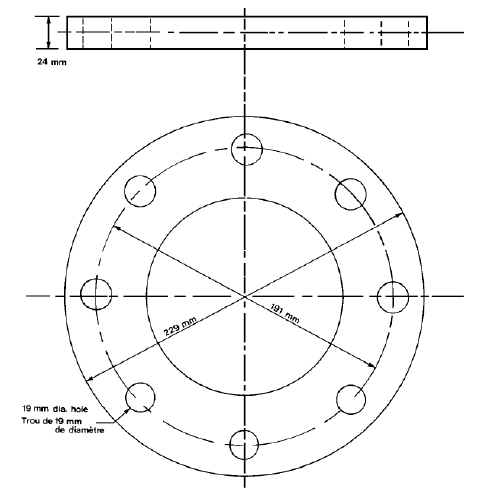
10.1.7.
Reserve
of fuel oil
Sufficient
fuel on board enables the vessel to:
① complete its intended voyage within the zones and
to leave all zones, or
②
reach a refueling place within any zone during
its intended voyage
In addition to the above ①
and ②, Arctic class ships are to meet the
requirements for a reserve of fuel for domestic purposes sufficient for a
period of 30 days.
10.1.8. Reserve
of fresh water;
in the expected navigation, the ships are to meet the requirements for a
reserve of sufficient fresh water, or equipment capable of producing sufficient
fresh water during its intended voyage to enable the ship to:
① complete
its intended voyage within the zones and to leave all zones, or
② reach a
place where fresh water is obtainable within any zone during its intended
voyage
10.1.9.
In addition to the above ① and ②, Arctic class ships are to meet the
requirements for a reserve of fresh water for domestic purposes sufficient for
a period of 30 days or equipment capable of producing such fresh water.Requirements
for ice navigator:
(a)
be qualified to act as master or
person in charge of the deck watch in accordance with regulations made pursuant
to the Canada Shipping Act; and
(b) have served on
a ship in the capacity of master, or person in charge of the deck watch for a
total period of at least 50 days, of which 30 days must have been served in
Arctic waters while the ship was in ice conditions that required the ship to be
assisted by an icebreaker or to make maneuvers to avoid concentrations of ice that
might have endangered the ship.
10.1.10. Discharge of sewage and oil or oily mixture water: on the condition that it meets
the requirements of MARPOL, discharge of sewage as may be generated on board that ship is allowed, while discharge of
oil sewage is prohibited;
Arctic
Pollution Prevention Certificate: the Certificate is not mandatory; for
non-Canadian ships, the Surveyor, and approved classification societies may
issue ASPPR-compliance certificates upon examinations;
10.2 Requirements for
issuance of certificates about the compliance of CCS ships with Arctic waters
pollution prevention rules at the request of the shipping company
10.2.1. At the request of shipping company, when
to issue a certificate about the compliance of CCS ships with Arctic pollution
prevention rules, the Surveyor is to check the following items, and, to the
satisfaction of the Surveyor, Arctic pollution prevention compliance
certificate printed on papers (Form SOC(CAN-APP)with CCS emblems is to
be applied. The examination is NS_ADS(CAN-APP);
10.2.1.1. Determine the ship class by the
ice strengthening notation; for ship class corresponding to CCS ice
strengthening notation, refer to the above 10.1.3.2;
10.2.1.2.
Check
the certificate, verify the effectiveness of the Classification Certificate, Passenger Ship Safety Certificate (if applicable), Cargo Ship
Construction Safety Certificate, Cargo Ship Equipment Safety Certificate, and
International Load Line Certificate.
10.2.1.3.
Check the arrangement of refueling
station and specification of flanges;
10.2.1.4.
Check
the reserve of fuels;
10.2.1.5.
Check
the reserve of fresh water;
10.2.1.6.
Check
the manning on board: ice master is to be arranged, unless otherwise the ship ping
is on open water. For the definition of “open water”, refer to The Arctic Ice Regime Shipping System(AIRSS) Standards, which is published by Ship Safety, Transport Canada in June 1996, and as amended from time to time.
10.2.1.7.
For Type B ship with fuel load of 453m3 and above (CSA Ice B1), the
additional requirements for shipping in Zone 6 from August 1st to
August 24th (time allowed for Type B Ship to navigate in this zone:
August 25th to September 30th each year):
(1)an ice breaker
available for escort duties; and (2)where the
ship carries oil as cargo, it is escorted by an icebreaker that has on board
the means to effect an immediate response to an oil spill..
10.2.1.8.
Data
verification: verify if the ship is fitted with Arctic Waters Pollution Prevention Act, Canadian Arctic Shipping Pollution Prevention Regulations
and appendixes. The master is required to be familiar with the above
regulations and appendixes.
10.2.2 Effectiveness of ASPPR Compliance
Certificate: The effective term of ASPPR Compliance Certificate is one year for
the maximum, no later than the first March 31st following the date
of issuance. If it is issued on April 1st 2011, the effective term
is not to exceed March 31st 2012. Note: other certificates remain
effective during the time.
10.2.3 Ineffectiveness of the ASPPR
Compliance Certificate: if the certificates as mentioned in 10.2.1.2
lose the effectiveness, the ASPPR Compliance Certificates is to be in abeyance
at the same time.
10.2.4 For compliance certificate format,
refer to the appendix.
10.2.5 Filling in the Compliance Certificate:
10.2.5.1. For Type A, Type B, Type C, and Type D
ships, the values of maximum/minimum draughts fore and aft are to be obtained
from the approved ice strengthening structural charts and other charts. In case
of insufficient data on board, follow the requirements of RULES FOR
CLASSIFICATION OF SEA-GOING STEEL SHIPS. When it is difficult to be sure of the
data on site, contact the Plan
Approval Center.
For Type E ships, the values of
maximum/minimum draughts fore and aft are to be obtained from the approved “Damage
Stability Calculation” or “Final Loading Manual”.
N12 Issuance of Statement of Compliance for equipment required by Suez Canal Authority Rules of Navigation
12.1 In addition to the provisions of SOLAS, IMDG
Code if carrying dangerous cargo, MARPOL 73/78, International Regulations for
Preventing Collisions at Sea (COLREGS) and all laws, orders, and regulations
issued by the Egyptian Government, all ships transiting through the Suez Canal
are required to comply with the conditions stated in the Rules of Navigation
(http://www.suezcanal.gov.eg /NR.aspx).
12.2
Equipment requirement for the ships transiting through the Suez Canal
12.2.1 Accommodations and spaces
12.2.1.1
A suitable (Officer Class) accommodation shall be provided for pilot.
In Art.42.1 of the Rules of Navigation:
A suitable (Officer Class) accommodation is to be put at the pilot's disposal
while anchoring in the Bitter Lakes or making fast in mooring places alongside
the Canal. In case of no suitable accommodation available, the vessel will pay
extra dues of (1000 U.S. Dollar) for each relieving pilot.
12.2.1.2 A sheltered place shall be
provided for three to six mooring boatmen and two shore electricians for the
projector during the transit.
In
Art.42.2 of the Rules of Navigation: A sheltered place is to be provided for
the mooring boatmen (3 to 6 men according to the size of the vessels) and two
shore electricians for the projector, during transit. The numbers of mooring
boatmen may be determined according to Art.20 in the Rules of Navigation: three
men for ship up to 5000SC.GT; and six men for ship above 5000SC.GT.
“Sheltered
place” is not defined and explained in the Rules of Navigation, it can be
interpreted as a place with awning sheltered from the sun and rain, and which
can accommodate 3 to 6 mooring boatmen and two shore electricians on the open
deck of the ship.
Normally
there are no sheltered spaces were specially provided to the mooring boatmen
and shore electricians on the ships transiting the Suez Canal, but in general
some spare rooms are available for tallymen, dockers etc. as rest use on the
main deck when ship gets alongside the wharf. Therefore, it is considered that
these rooms can meet the requirements of “sheltered place” in Rules of
Navigation.
12.2.2 Mooring and anchoring
12.2.2.1 Ships shall be fitted with well
maintained lifting appliances capable of lifting mooring boats of 4 ton weight
(including three crew members).
In
Art.20.5 of the Rules of Navigation: Ships must be fitted with well maintained
lifting appliances capable of lifting mooring boats of 4 ton weight (including
three crew members). The handling of mooring boats must be carried out safely,
well clear from the ship's propellers. The hire, replacement, maneuvering,
additional provision, etc. for mooring boats may refer to Art.20 of the Rules
of Navigation.
12.2.2.2 At least six flexible floating
mooring ropes shall be provided. For ships equipped with tension mooring wires,
the number of floating ropes may be reduced to four. Any mooring lines, likely
to produce sparks by their manipulation are absolutely forbidden on board
petroleum tankers, LPG, LNG as well as on board any vessel carrying inflammable
substances.
In
Art.19.1 of the Rules of Navigation: At least 6 flexible floating mooring ropes
of appropriate size for the vessel, in good condition, fitted with spliced eyes
must be ready at suitable points on deck for any emergency. All arrangements
must be made for their quick handling. Meanwhile, according to Art.19.2, for
vessels equipped with tension mooring wires, the number of floating ropes may
be reduced to 4. It is to be noted, however, that any mooring lines, likely to
produce sparks by their manipulation are absolutely forbidden on board
petroleum tankers, LPG, LNG as well as on board any vessel carrying inflammable
substances. In addition to, the relevant requirements of rope handing and specification
of wire cables may further refer to Art.19.3.
It
is noted that the number of mooring rope is not to be less than four for
EN>205 and not less than six for EN>2530 in the Rules of the Society.
12.2.2.3 All transiting ships shall be
equipped with two classed anchors located forward of the collision bulkhead.
One working anchor shall be provided at forward for ship less than 1500SC.GT.
In
Art.23.1 of the Rules of Navigation: Any transiting vessel must be equipped
with two classed anchors located forward of the collision bulkhead. Each anchor
must be fitted with its own chain or wire cable, and be capable of being
released, by gravity and raised by means of a windlass or capstan. Meanwhile,
according to Art.23.2 in the Rules of Navigation, In lieu of it, vessels of
less than 1500 SC.G.T must be equipped with one working anchor located forward.
It
is noted that at least two bower anchors are to be equipped for all ships in
accordance with the requirements of Section 2, Chapter 3, PART TWO in the Rules
for Classification of Steel Sea-going Ships of the Society. Hence, above
requirements will be in compliance with if the ship meets this Rules.
12.2.3 Fire-fighting equipment
All
ships shall be provided with two fire wires.
In
Art. 61.3 of the Rules of Navigation: As a precautionary measures, on
approaching Canal, all vessels must have a fire wire hanging over the side
ready for use fore and aft in case of emergency, before entering Canal. It may
also refer to Art. 37.3 and Art.19.3(c) in the Rules of Navigation.
12.2.4 Pilot transfer arrangements
Pilot
ladders approved by societies shall be equipped.
In
Art.24.1.1 of the Rules of Navigation: In Anchorage Areas, outside the Canal
North or South, pilot ladders can be used to embark, and disembark pilots. The
ladder shall be secured in such a position that each step rests firmly against
the vessel's side and so that the pilot can have safe access to the vessel.
Whenever the distance from sea level to the point of access to the vessel is
more than 12 feet (3.65 meters), access from the pilot ladder to the vessel
shall be by means of an accommodation ladder or other equally safe and
convenient means. And according to Art.24.2.1, Accommodation ladders are to be
used in the Canal harbours, and lakes to embark and disembark pilots.
12.2.5 Luminaires
12.2.5.1 Searchlights
12.2.5.1.1 Ships shall be equipped with searchlights
which are approved and certified by societies, and they shall meet the relevant
requirements of Rules of Navigation.
In
Art.28.2.10 of the Rules of Navigation: The searchlight must have a certificate
for the “Type Test”. This “Type Test certificate” shall be issued by one of the
Classification Societies, and can certify it meets the specifications required
by the Rules of Navigation. This type test must include illuminate test to
fulfill the above specifications. The original to be submitted to Suez Canal
Officials and thereby, after test by SCA Inspector, the searchlight can be
accepted.
The
searchlights shall be placed on the bow in the central axis of the vessel and
meet the specifications specified in Art.28.2 of the Rules of Navigation, including
range of radiation, power, material, watertightness, heat radiation, etc.
A
portable projector can be hired locally from the Canal Mooring and lights
Company. L.P.G. vessels, L.N.G. vessels, vessels entering the Canal, direct
from sea, must be provided with their own searchlights. For vessels fitted with
their own projector, two shore electricians should operate the projector during
the transit.
Any
non-compliance cases and relevant exemptions, please further refer to Art.28 of
the Rules of Navigation.
12.2.5.1.2 Electric cables installations
for searchlight and all connections leading to it shall be permanently fixed,
insulated and gastight. At the end of the cables, a fixed and gastight
non-explosive type socket should be installed close to the searchlight.
In
Art.28.3 of the Rules of Navigation: On vessels carrying Petroleum products,
L.N.G. or inflammable substances or vessels Not Gas Free, electric cables
installations for searchlight and all connections leading to it must be
permanently fixed, insulated and gastight. At the end of the cables, a fixed
and gastight non-explosive type socket should be installed close to the
searchlight.
12.2.5.1.3 The number of generators and
their individual power output shall be sufficient to ensure uninterrupted
functioning of the searchlight in the event of stoppage of one of the
generators.
In
Art.28.4 of the Rules of Navigation: On board vessels, electrically propelled
or having electrically driven gear (steering, winches, etc.) the number of
generators and their individual power output must be sufficient to ensure
uninterrupted functioning of the searchlight in the event of stoppage of one of
the generators. No exception to this rule will be allowed except when there is
an independent generator and circuit on board specifically set apart for the
searchlight.
12.2.5.2 Overhead lights
Overhead
lights visible all round the horizon with a minimum range of 200 m shall be
equipped.
In
Art.29 of the Rules of Navigation: Overhead lights visible all round the
horizon with a minimum range of 200 meters (about 650 feet). Kind of lamps is
to be the non-explosive type.
12.2.5.3 Bridge wing projectors
Bridge
wing projectors shall be provided on either side of the bridge, with the power
about 4 LUX and the minimum range 200m.
In
Art.30 of the Rules of Navigation: Bridge wing projectors on either side of the
bridge must be fitted to show the Canal banks clearly during the transit and
mooring operations, they must have the following characteristics: Power about 4
LUX at an atmospheric transmission factor (T = 0.74) and minimum range 200m.
Kind of lamps to be the non-explosive type.
12.2.5.4 Funnel
Funnels
shall be lit to facilitate the identification of the ship by night.
In
Art.31 of the Rules of Navigation: Funnels must be lit to facilitate the
identification of the vessel by night.
12.2.6 Navigation equipment
The
rudder angle indicator and engine RPM indicator in wheelhouse shall be so
located and illuminated as to be easily visible by the pilot.
In
Art.22 of the Rules of Navigation: There must be a rudder angle indicator and
an engine RPM. indicator in the wheelhouse so located and illuminated as to be
easily visible by the pilot. If they are defective, please further refer to the
requirements in Art.22.
It
is noted that Reg. V/19.2.5.4 of SOLAS requires the indicators for rudder,
propeller, thrust, pitch and working mode shall be clearly seen in the conning
position onboard. Hence, ships in compliance with the SOLAS are generally
regarded to meet this requirement.
12.2.7 Signaling equipment
12.2.7.1 Red Suez Canal sternlight may
be available.
In
Art.92.B(13) of the Rules of Navigation: In the Canal when made fast, the 2
white lights are extinguished and a red light put on aft all the time the
vessel is moored until actually underway This requirement has obvious
difference from the requirement of anchoring light in COLREG.
12.2.7.2 Special signals used by ships
transiting through the Canal shall be equipped.
Art.
92.B of the Rules of Navigation specifies the special signals used by ships in
ports and in the Canal. The ship’s intention is indicated through exhibition of
different combinations of signals, such as applying for pilot, exemption for
survey, towing boat, no mooring boat, no searchlight, mooring condition, etc.
The signals equipped shall meet the requirement of Art. 92.B in the Rules of
Navigation.
12.2.8 Draught marks
All
ships shall be assigned draught marks at the stem, amidship (including Pilmsoll
Mark and Deck Line) and stern (stern post or rudder post).
In
Art.35 of the Rules of Navigation: All vessels shall have the draught plainly
marked and painted upon the stem, amidships (including Plimsoll Mark and Deck
Line) and stern post or rudder post according to load line convention. It is
noted that the mark is also required in Reg. II-1/5 in SOLAS, and it is only
required to be marked at stem and stern, however, the Suez Canal Rules of
Navigation requires that the draught shall also be marked at amidship, and the
location of stern shall be at the stern post and rudder post.
12.2.9 Additional requirement of container ships
Container
ships carrying different sizes of containers must have their own spreaders.
In
Art.21 of the Rules of Navigation: Containerships are advised to have their own
spreaders (slings) to assist with the unloading and reloading of containers
whenever necessary. However, containerships carrying different sizes of
containers must have their own spreaders.
12.3
Issuance of Statement of
Compliance and survey report
12.3.1 The drawings in relation to equipment
requirements in Rules of Navigation shall be approved by CCS Plan Approval
Center, the site surveyor is to carry out inspections and verifications for
equipment onboard the ships meeting the Suez Canal Authority Rules of
Navigation in accordance with specific shipboard arrangements, approved
drawings and test results and, if in satisfactory condition, issue the
“Statement of Compliance with the Suez Canal Authority Rules of Navigation”
(Form SOC(SCA-RN)) on the paper with the Society’s emblem and the survey report
(Form RNc), the kind of survey is notarial survey NS_ADS(SCA-RN).
12.3.2 The Statement of Compliance is not issued on
behalf of the Suez Canal Authority, it only represents the Society’s
understanding of requirements in Rules of Navigation for equipment onboard
ships transiting through the Suez Canal, and does not exclude the potential
additional surveys or evidences required by Suez Canal Authority to the ships
transiting through the Suez Canal.
12.4 Explanation
The
Suez Canal Authority Rules of Navigation may be available from
http://www.suezcanal.gov.eg/NR.aspx, and the surveyors shall pay attention to
any changes of the Rules of Navigation.
N13 China Emission Control Areas (2015 Technical Notice 39/Total No.200)
The latest air pollution prevention regulation, namely the Marine Emission Control Areas Implementation Scheme for Pearl River Delta, Yangtze River Delta, Bohai-rim Waters (hereinafter referred to as "China Emission Control Areas Implementation Scheme" or "China ECAs Implementation Scheme") was released by the Ministry of Transport (MOT), China, on 4 December 2015, which will enter into force from 1 January 2016.
1. Applicable Ships
The China ECAs Implementation Scheme is applied to these ships when they are sailing, anchoring or operating in China ECAs, however, warships/military ships, sport ships/boats, or fishing ships/vessels are excluded.
2. China ECAs Specification
Currently there are three Emission Control Areas are defined, including Pearl River Delta, Yangtze River Delta, Bohai-rim Waters.
3. Emission Control Requirements within China ECAs
Generally speaking, NOx emission control shall be in line with the requirements stipulated in current MARPOL Annex VI for these international voyage ships, ships other than international voyage ships shall comply with domestic laws and regulations. While SOx emission control must follow the timeline (Table 1) as follows:
Table 1: Timeline for implementation of SOx emission control
|
Date |
Sulphur content in fuel (m/m) |
Applicable Area |
Time |
|
2016.01.01——
2016.12.31 |
≤0.5%, or equivalent measures |
The ports which are in favorable conditions (voluntary) |
At berth (except within 1 hour after arrival and within 1 hour before departure) |
|
≤3.5% |
Area within China ECAs other than these ports which are in favorable conditions (mandatory) |
All time |
|
2017.01.01——
2017.12.31 |
≤0.5%, or equivalent measures |
Core ports (mandatory) |
At berth (except within 1 hour after arrival and within 1 hour before departure) |
|
≤0.5%, or equivalent measures |
Ports other than core ports which are in favorable conditions (voluntary) |
At berth (except within 1 hour after arrival and within 1 hour before departure) |
|
≤3.5% |
Area within China ECAs other than core ports and other ports which are in favorable conditions (mandatory) |
All time |
|
2018.01.01——
2018.12.31 |
≤0.5%, or equivalent measures |
All ports (mandatory) |
At berth (except within 1 hour after arrival and within 1 hour before departure) |
|
≤3.5% |
Area within China ECAs other than all ports (mandatory) |
All time |
|
2019.01.01——
2019.12.31 |
≤0.5%, or equivalent measures |
Area within China ECAs(mandatory) |
All time |
|
From 2020.01.01 |
≤0.1%, or equivalent measures |
Area within China ECAs;
Expansion of China ECAs;
Other possible measures |
Possible implementation after completion of assessment before 2019.12.31 |
* The Port Authorities may release the relevant notice in advance (especially these core ports such as Shanghai, etc.).
** Equivalent measures mean using ashore cold iron, using clean energy such as liquefied natural gas (LNG), or using an exhaust gas cleaning system (EGCS).
*** In case of any conflict between the explanations contained above and the original Chinese text as well as authentic English text later released by the MOT, the MOT text shall prevail.
4. Action may be taken
4.1 China Maritime Safety Administration (MSA) may consequently develop the implementation procedures to enhance the inspections in order to verify whether these applicable ships are compliance or not. In this regard, these applicable ships are suggested to establish and implement the training procedures, bunking procedures, switch-on/switch-off procedures and operation procedures, and supporting document (such as fuel delivery note (FDN), oil record book, Log Book, etc.) and samples should be kept onboard.
4.2 Besides the release of several Circulars and Technical Information such as (2014) TN.38/Total No.160, (2010) Circ.17/Total No.17, etc., CCS also issued the Guidelines for Use of Low Sulphur Fule Oils in Ships with the aim to assist the customers to handle the issues of low sulphur fuels oils, if necessary, shipping companies could use these documents to assess, evaluate, design and refit their ships properly.
CCS could also carry out the drawings/documents approval, survey and certification upon request by shipping companies if need. “III N5.5 Decision on sampling methods and frequency regarding the verification of sulphur content of marine fuels for ships calling in Member States of the European Union (COMMISION IMPLEMENTING DECISION(EU)2015/253) ” could be regarded as the reference.
III-N 鉴 证 检 验
Notarial Surveys
序号 分目录
No. Sub-contents
N1 一般规定
General Provisions
N2 签发美国环保署VGP要求的坞检声明
Statement of Dry Docking Survey as Required by US EPA VGP
N3 签发满足有关US 33 CFR要求的证明文件
Certificate of Compliance with Requirements of US 33CFR Regulations
N4 签发蒸汽控制系统符合US 46 CFR规定的证明文件
Certificate of Compliance with Requirements of US 46
CFR Regulation on Vapour Control System
N5 欧盟对船舶硫氧化物排放控制要求
Certificate of Compliance with Requirements of EU
Regulation on Control of SOx Emissions From Ships
N6 AMSA对直升机降落甲板(或舱口盖)强度要求
Certificate of Compliance with Requirements of AMSA
Order on Strength of Helicopeter Landing Site
N7 沙特阿拉伯港口当局对起货设备检验的要求
Certificate of Compliance with Requirements of National
Regulations of the Government of Saudi Arabia
N8 签发满足石油行业组织对液货船结构和设备要求的符合证明文件
Statement of Compliance with Guidlines of Oil
Organizations for Structure and Equipment of Tanker
N9 现有船状态评估程序(CAP )
Condition Assessment Program for Existing Vessels(CAP)
N10 加拿大北极水域防污染要求的检验
STATEMENTOF COMPLIANCE OF ARCTIC
POLLUTION PREVENTION
N1 一般规定
1 一般规定
1.1 船舶鉴证检验是指应船东申请而进行的公正性检验,检验完成后出具相应的检验报告和证明文件,以证明船舶的技术状况符合入级、法定要求以外的特定标准、规范、法规或规格书的要求:如船舶为提前实施尚未生效的公约而申请本社签发符合证明的检验,或公约生效后非缔约国船舶所属船公司申请本社签发符合证明的检验,以及船东为了满足船旗国、港口国、区域主管机关的特殊要求而申请本社签发符合证明的检验。
1.2 对于船舶为提前实施尚未生效的公约而申请本社签发符合证明的检验,或公约生效后应非缔约国船舶所属船公司申请本社签发符合公约要求证明文明的检验,执行检验时应参照公约和船旗国政府的有关规定,及本须知第III分册的相应内容。
1.3 检验完成后签发的证明文件,如无统一格式,可使用带社徽的空白证书纸(Form CSB-2)打印,证书上注明“应船公司申请签发”,检验种类为鉴证检验(NS_ADS);但对于我社经船旗国主管机关授权签发符合证明的检验,应理解为法定检验,此情况下签发的证明文件格式上将注明“应主管机关授权签发”,具体授权范围参见本须知III-K各船旗国特殊要求部分的内容。
N2 签发美国环保署VGP要求的坞检声明
VGP有关介绍
美国环保署(EPA)根据美国联邦“清洁水法(CWA)”有关规定,于2013年3月颁布了最新版本(Final 2013 VGP)的“国家污染物排放消减(NPDES)船舶通用许可”(以下简称“VGP”)。“VGP”长达194页,有关主要内容摘录介绍如下:
2 签发美国环保署VGP要求的坞检声明
2.1 VGP有关介绍
美国环保署(EPA)根据美国联邦“清洁水法(CWA)”有关规定,于2009年2月2013年3月颁布了最新版本(2/5/2009)(Final 2013 VGP)的“国家污染物排放消减(NPDES)船舶通用许可”(以下简称“VGP”)。“VGP”长达160194页,有关主要内容摘录介绍如下:
2.1.1 “VGP”生效时间:自2008年12月19日(对阿拉斯加和夏威夷为2009年2月6日)至2013年12月19日至2018年12月19日。
2.1.2. “VGP”适用范围:
.1在美国水域-包括其领海(距海岸3海里内)或内河-运营的、船长为24.08米及以上的所有美国籍或外籍商用船舶。
.2不适用于娱乐船舶。
.3EPA期望“VGP”适用于船长为24.08米(79feet)以上的船舶,但如可行,长度小于24.08米的商业渔船和其他非娱乐船舶也可适用于“VGP”,或者适用于EPA发布的sVGP。
.4辅助船艇,如救生艇、救助艇、船载驳等,也可适用“VGP”。
2.1.3. “VGP”相关规定简介
2.1.3.1 VGP第1至第4部分给出所有适用船舶正常运营产生的污染物排放通用要求和具体限制条件;第5部分给出特定船泊(大型游艇、中型游艇、大型渡轮、驳船、油船和石油产品船、科研船、消防船和警用船、实施压载水处理系统试验的船舶等)附加特殊要求;第6部分给出了各洲和印第安保护区的特殊要求;第7 至15部分为附录,附录A至附录K包括定义、意向通知(NOI )、终止通知(NOT )、附加许可要求、附加信息等。
2.1.3.2 根据VGP第1部分1.2.2规定,VGP适用以下2627类船舶污染物排放:甲板冲洗污水、舱底水/油水分离后污水、压载水、防污底涂层沥出物、清水泡沫溶液(AFFF)、锅炉冷凝水、阴极保护、锚链舱污水、可调距螺旋桨和推进器液压油及其它油-海水界面(包括明轮、尾轴管、螺旋桨轴、稳流器、舵轴、全回转推机器、吊舱式推进器等)的润滑油排放、蒸馏和反渗透盐水(海水淡化装置)、升降机井坑污水、消防总管系统、淡水管接头、燃气轮机清洗污水、生活污水灰水、动力汽油和补偿排放、机器处所非油类废水、制冷和空冷排放、海水冷却水舷外排放(包括非接触类型机器冷却水、液压系统冷却水、制冷系统冷却水)、海水管线防止生物污染、小船艇发动机湿排气、声呐导流罩水排放、船舶水下维修、井型甲板污水排放、船舶生活污水和灰水混合物、废气洗涤器废水排放、鱼舱污水等。
1)船舶油水界面使用环保润滑油
根据2013VGP第2部分2.2.9之规定,船舶在油水界面上必须使用环保润滑油(EAL),除非技术上不可行。这些油水界面包括但不限于:可调距桨、推进器液压油及其他油水界面(明轮、艉轴管、螺旋桨轴承、减摇装置、舵承、全回转推进器、吊舱式推进器、浸没的钢丝绳和机械设备)。EAL指可生物降解、最低限度毒性、非生物累积的润滑油,具体见VGP附录A之定义。
VGP所定义的“技术上不可行”包括以下三个方面:
1、没有经认可的满足设备制造商规格书要求的EAL产品(如油封)可供使用;
2、需预润滑的设备(如钢丝绳)没有可用的EAL替代产品;
3、船舶航经港口内无法获得满足制造商规格书要求的EAL产品,或者须等到船舶下次进干坞才能更换或使用EAL产品。
如果船舶适用上述“技术不可行”之情形,船东或经营人须在保留船舶上的记录文件上如实记录原因,必要时附有设备制造商提供的支持性材料,并在VGP要求的年度报告里向EPA报告非EAL的使用情况。另外,使用EAL并不代表船舶被授权排放有害数量的润滑油。EPA建议所有新造船经营人尽力使用基于海水的艉轴管润滑系统以避免自这些界面排放油类至水生环境。
2)除使用EAL外,VGP对油水界面的其他要求如下:
1、可调距桨、全回转推进器、吊舱式推进器、舵承及其他油水界面上的密封装置应保持在良好操作状态以使液压油或其他油类的渗漏减至最低。船舶的船东或经营人不得自任何油水界面排放有害数量的油类。如可行,应在干坞内对船舶可调距桨、推进器和其他油水界面上的装置进行维护保养。
2、当船舶不在干坞时应尽可能少地对艉轴管密封装置进行维护保养。如必须对艉轴管或其他油水界面上的装置进行维护保养或应急修理,且有可能排放出有害数量的油类,应使用合适的泄露处置设备(如围油栏)以控制溢油。应有直接通道至泄露处置设备以清除溢油。
3、在确保安全情况下,对拟浸没水中的钢索或机械设备涂抹润滑油,入水前应清除过量的润滑油。
2.1.3.3 根据VGP第1部分1.5.1规定,VGP的获取方式如下:
(1) 300总吨以下且压载水容量小于不超过8立方米的船舶:自动获得授权按VGP规定要求进行排放,不必向EPA提交“意向通知(NOI)”,但应填写附录K的“授权许可与检查记录表”(Form PARI),并一直在船上保存一份副本;
(2) 300总吨及以上、或压载水容量大于8立方米的现有船舶:应自2009年6月19日起且不晚于2009年9月19日按VGP第10部分附录E要求向EPA提交“意向通知(NOI)”以获取VGP。在提交NOI前且截止至2009年9月19日,船舶自动获得授权按VGP规定进行排放。EPA建议要求船舶通过电子方式(网址www.epa.gov/npdes/vessels/eNOI)网上提交NOI。各类船舶提交NOI期限要求如下:
|
船舶类别
|
提交NOI期限
|
排放授权日期
|
|
2009年9月19日及之前交付使用的现有船舶授权按2008VGP排放的船舶
|
不晚于2009年9月19日不迟于2013年12月12日或在美国水域排放前7天,取晚者
|
在提交NOI前允许按VGP排放至2009年9月19日;如EPA在2009年9月19日或之前收悉NOI,则船舶按VGP排放授权不间断。
对于电子NOI:
2013年12月19日,或者,如果截止2013年12月12日未提交,EPA收悉NOI后7天。
对于纸质NOI:
EPA收悉NOI后30天。
|
|
已获VGP船舶更换船东/管理公司
|
更换船东/管理公司之日
|
更换船东/管理公司日期、或EPA收悉NOI日期,以晚者为准
|
|
20092013年912月19日之后交付使用的新船
|
对于电子NOI:
在美国水域排放前7天。
对于纸质NOI:
拟在美国水域排放日期至少提前30天
|
对于电子NOI:
EPA收悉NOI后7天。
对于纸质NOI:
EPA收悉NOI之后30天
|
|
20092013年912月19日之后交付使用的现有船舶(未获VGP)
|
对于电子NOI:
在美国水域排放前7天。
对于纸质NOI:
拟在美国水域排放日期至少提前30天
|
对于电子NOI:
EPA收悉NOI后7天。
对于纸质NOI:
EPA收悉NOI之后30天
|
2.1.3.4 VGP的有效期限
按VGP第1部分1.5.2规定,如果在现VGP规定失效期限(20132018年12月19日)前EPA未重新签发或替换VGP,则现VPG保持有效。在下述情况下现VGP将失效(以早者为准):
(1) 船舶已经取得的VGP经重新签发或替换时。相应船方需及时并适当地按新许可的要求重新递交一份完整的NOI以取得新的排放许可;或
(2) 船舶递交了“终止通知(NOT)”;或
(3) 对于不需递交NOI即可获得排放许可的船舶,签发新的VGP时;或
(4) EPA对要求持有单独排放许可的船舶签发、或者拒绝签发单独排放许可时;或
当EPA正式决定不再重新签发VGP,并对现VGP所覆盖的排放以变通排放许可或单独排放许可方式给出一个合理的时间期限时,现VGA排放许可终止于所述的时间期限结束时。
2.1.3.5 VGP的终止
(1) 对于通过提交NOI取得VGP的船舶(300GT及以上或压载水容量8立方米以上船舶),在以下情况下30天内需通过提交“终止通知(NOT)”以终止排放许可:
.船舶更换新船东或管理公司;
.船舶永久性停止在美国水域运营而不再进行排放;
.船舶取得了EPA签发的单独排放许可或变通排放许可。
(2) 对于不需通过提交NOI取得VGP的船舶(300GT以下且压载水容量8立方米及以下船舶),在上述情况下不必提交“终止通知(NOT)”即自动终止排放许可。
(3) EPA建议通过电子方式提交NOT(www.epa.gov/npdes/vessels/eNOI),完成提交后当日晚11时59分终止所授权的排放许可。
2.2 船舶自我检查及报告要求
2.2.1 根据VGP第4部分“检查、监控、报告和记录保管”的规定,取得VGP的船舶应进行自我检查监控(包括常规目检、分析监控、综合年度检查、干坞检验报告等)并保存相应记录,另对压载舱有附加的记录要求。所有要求的记录应由船舶保管至少3年,供EPA或其授权人员必要时核查。
1.2.2 船舶应向EPA提交年度报告。当船舶发生不符合VGA排放限制、及排放物中危险品和油类超过规定数量等情况下应按VGA规定的时限报告EPA。另EPA要求各船舶在获VGP后30个月至36个月期间向EPA做一次反馈报告(可通过网址www.epa.gov/npdes/vessels/eNOI填报,预计填报时间不超过30分钟),以作为EPA下次更新VGP的参考依据。
2.3 我社应船公司申请对CCS级船舶签发坞检声明的有关规定
2.3.1 根据VGP第4部分第4.1.4条规定,取得VGP的船舶应保存船级社或主管机关签发的干坞检验报告供EPA或其授权代表查阅。如船舶未持有船级社或主管机关签发的坞检报告,则船方也可自行准备一份这样的坞检报告。据此,我社可应船公司申请,对CCS级船舶签发坞检声明(Form SOC (US-VGP)),检验种类为鉴证检验NS_ADS(US-VGP)。
结合干坞检验签发坞检声明
对CCS级船舶进行坞检时,应船公司申请,验船师在对以下项目进行检查、验证满意情况下,使用社徽证书纸签发坞检声明(Form
SOC (US-VGP)):
2.3.2.1 对CCS级船舶进行坞检时,应船公司申请,验船师在对以下项目进行检查、验证满意情况下,使用社徽证书纸签发坞检声明(Form SOC (US-VGP)):
(1) 检查确认船舶锚链舱的沉淀物、活海生物和其他重要的成分已经清除。
(2) 检查确认船体外板、螺旋桨、舵、推进器格栅、海底阀及其它船体水下外表面上所附着的海生物已经予以清除或抑制。
(3) 验证船舶现有的或新施涂的防污底涂层不含在美国水域禁止使用的生物杀虫剂或毒性成份(符合AFS公约要求的防污底系统可认为等效满足该要求)。对于在美国境内采购或分发的防污底涂层,无论施涂、维修或移除,均应验证其与FIFRA(美国联邦杀虫剂、杀菌剂、灭鼠剂法案)标签相一致。
(4) 如设有阴极保护系统,检查确认阳极块、介质膜已经予以清洗和/或更换,以减少碎片脱落。
(5) 所有的防污染控制设备(包括油水分离器、排油监控系统等,如适用)处于正常工作状态。
(6) 对舵承、尾轴管、可调距螺旋桨叶片(如安装)等的防护密封装置进行检查并在必要时更换。
2.3.3 对现有船舶补发坞检声明
2.3.3.1 如现正在或拟于美国水域运营的CCS级船舶未持有上述VGP要求的最近一次坞检声明,船长/船公司可按VGP第4.1.4条所列项目进行验证后自行签发坞检符合声明。船公司如申请本社签发坞检声明,则可根据船期就近向我社有关检验单位提交申请,我社验船师将根据2.3.2.1所述的6方面检验项目核查船舶最近一次坞检、防污底检验、防污染检验报告、及确认最新船舶检验信息中无上述项目遗留条件,并尽实际可行登轮对上述项目进行检查或验证结果满意后签发坞检声明。
2.4 参考信息
本段涉及的美国环境保护署有关VPG规定及其相关最新要求,请到以下官方网站查询、下载:http://cfpub.epa.gov/npdes/home.cfm?program_id=350。
N3 签发满足有关US 33 CFR要求的证明文件
3 签发满足US 33 CFR要求的证明文件
3.1 本节的要求适用于申请我社审图满足US 33 CFR Part 151, 155, 157, 159, 164 等,和申请签发US 33 CFR证明文件的悬挂非美国国旗的无限航区的新建的一般货船及油船。
3.2 USCG 对航行至美国水域非美国旗船舶要按照US 33 CFR的要求对其进行PSC检查。USCG 对航行至美水域的外旗船检验的依据主要是the Code of Federal Regulations Title 33 (33 CFR)---- “Navigation and Navigable Waters”,the Code of Federal Regulations Title 46 (46 CFR)---- “Shipping”及现行有效的SOLAS 公约、MARPOL 73/78 公约、载重线公约等公约的规定。33 CFR及46 CFR,该依据除包含了与现行有效的SOLAS 公约、MARPOL 73/78 公约、载重线公约等公约规定一致的大部分要求(USCG 不接受上述公约的个别要求,如MARPOL 73/78 公约附则I 第19.4条、第29.2.3.2和29.2.3.3条有关污油水舱容量小于2%载油量的规定等)外,还规定了美港口国当局自己的一些要求。对于我社签发US 33 CFR证明文件来讲,主要审/检查申请签发USCG 证明文件的船舶在防止油污染、生活污水污染及垃圾污染、航行安全等方面的设备及布置是否满足US 33 CFR的要求,这些要求主要在33 CFR 中。主要包括PART 151—载运油、有毒液体物质、垃圾及压载水的船舶、PART 155—防止油类或有害物质污染规定、PART 157—散装油类船舶海上环境保护规定、Part 159—船用生活污水设备和Part 164—航行安全规定这几部分的要求。由于该证明文件的签发主要涉及审图部门的工作,这儿就不再详述了,具体内容请参考规范与技术管理部TD002通函,关于33 CFR的条文可从下列网站查阅:http://www.access.gpo.gov/nara/cfr/cfr-table-search.html。
3.3 应船公司申请,验船师根据船上的具体布置、批准的图纸和试验结果进行检查、验证满意的情况下,使用社徽证书纸签发满足US 33 CFR要求的证明文件(Form SOC(US-33 CFR)),检验种类为鉴证检验 NS_ADS(US-33 CFR)。本社签发的满足US 33 CFR要求的证明文件应由船方在抵达美国港口时送USCG确认盖章并永久保存在船上。
3.4 签发USCG 证明文件时,请注意不同吨位、不同尺度、不同船型的船舶对US 33 CFR条款的适用情况,具体条文可从下列网站查阅:http://www.access.gpo.gov/nara/cfr/cfr-table-search.html。
N4 签发蒸汽控制系统符合US 46 CFR规定的证明文件
4 签发蒸汽控制系统符合US 46 CFR规定的证明文件
4.1 根据美国the Code of Federal Regulations Title 46 (46 CFR) PART 39—VAPOR CONTROL SYSTEM的要求,悬挂非美国旗的外国液货船的蒸汽控制系统必须获得入级船级社的符合证明,否则将不能在美国港口使用。
4.2 对加入我社船级的船舶的VCS审图和检验发证工作规定如下:
4.2.1 新造液货船如果申请VCS附加标志,应按照我社《钢规》对VCS的要求审图和检验后,授予VCS(或VCS-T)附加标志,并可应申请方申请签发US 46 CFR符合证明。
4.2.2 对于现有液货船,如果船舶建造是其VCS已经按照《钢规》2003修改通报进行审图和建造检验,并已授予VCS(或VCS-T)附加标志的船舶,可以认为已经符合46 CFR Part 39对VCS的要求,可应船东申请,核查设计参数和试验结果后,签发US 46 CFR符合证明。
4.2.3 对于未授予VCS附加标志的现有液货船,如果船东申请签发US 46 CFR符合证明,则必须要求船东按照《钢规》要求送审的图纸和资料,送审图中心批准后,经现场检验满意,方可授予VCS(或VCS-T)附加标志,并签发US 46 CFR符合证明。
4.2.4 VCS的检验要求可参见本须知III-D5部分5.2.3.4条,但1990 年7 月23 日以前装船系统的货舱高位和溢出报警系统不必满足相互独立、故障和失电报警、以及自诊的功能要求,但现有系统只能经USCG 特别批准,在特定的港口设施使用。如果VCS 和IGS 连接,则“IGS 手册”应包括VCS 的相关程序。
4.3 应船公司申请,验船师根据船上VCS的具体布置、批准的图纸和试验结果进行检查、验证满意的情况下,使用社徽证书纸签发US 46 CFR符合证明(Form SOC(US-VCS)),检验种类为鉴证检验NS_ADS(US-VCS)。本社签发的US 46 CFR符合证明应由船方在抵达美国港口时送USCG确认盖章并永久保存在船上。
N5 欧盟对船舶硫氧化物排放控制要求
5. 欧盟对船舶硫氧化物排放控制要求(经2005/33/EC修正的1999/32/EC号法令)
5.1 除IMO法规要求外,船上燃油的硫含量控制还应满足下述要求;
5.1.1 如果燃油的硫含量超过1.0%m/m将不允许在被IMO规定为SECA(SOx Emission Control Area硫氧化物排放控制区)水域的欧盟成员国的领海、专属经济区和污染控制区内使用。
5.1.2 上述1.1.1燃油硫含量控制的适用日期:
.波罗的海水域(2006年8月11日起执行)
.北海水域含英吉利海峡(2007年8月11日起执行)
.对其他以后根据MARPOL附则VI第14(3)条规定为SECA水域(在IMO规定之日起12个月后开始执行)
5.2 2010年1月1日起,在下述情况下不得使用硫含量超过0.1%m/m的燃油:
.内河船使用(参见欧盟82/714/EEC法令)
.在欧共体港口停泊超过2小时的船舶(该要求不适用于停掉所有机器而使用岸电的船舶)
5.3 对于利用燃油转换满足控制硫含量要求的船舶,则燃油转换操作要记录在船舶日志上。
5.4 为适用欧盟法令2005/33/EC 修正的1999/32/EC 的4b 章的要求,对自2010年1月1日起,在欧盟港口停泊(包括系泊和锚泊)超过2 小时的船舶使用硫含量不超过0.1% m/m 的燃油的船舶设备进行的评估和改造、检验发证应注意下列事项:
5.4.1 安全评估、改造计划、船上换油程序和设备操作手册的要求:
(A) 安全评估
在船舶使用低硫燃油之前,船东或管理公司应向相关设备制造厂或专业设计公司(如原船的建造设计公司、原设备的产品设计公司)咨询,以确认这些设备是否可安全的使用低硫燃油,是否需要进一步对设备、管路以及相关布置进行改造,并请制造厂或专业设计公司对相关设备使用低硫燃油后可能出现的问题,进行分析和评估,给出相关对策和建议,最后做出评估报告。评估报告建议应至少包括对以下内容的分析和评估:
1、 对于柴油机包括主机(如某些船舶,停泊时需使用主机驱动一些设备;或停泊时主机检修后需运转主机进行试验等)辅机以及其他需要使用低硫燃油的设备(如焚烧炉等)及其附属设备
(1)低硫燃油的储存和隔离的安全性;
(2)低硫燃油输送包括管路系统和燃油泵的可靠性和适应性;燃油控制系统的安全性;
(3)低硫燃油与其他燃油转换的可行性;
(4)低硫燃油低闪点、低粘度和低润滑性对设备的影响(包括采取依据设备厂家的要求往低硫燃油中增加添加剂、燃油系统增加冷却设备等措施之后);
(5)使用低硫燃油后,柴油机气缸油的适用性;
(6)使用低硫燃油后柴油机延时发火和燃烧效果的影响;
2、对于燃油锅炉 :
(1)、(2)、(3)和(4)同上;
(5)使用低硫燃油后,炉内火焰探测与监控装置的适用性;
(6)使用低硫燃油后,燃烧器的适用性;
(7)使用低硫燃油后,锅炉燃烧控制系统的适用性;
(8)使用低硫燃油后,由于热值不同引起的蒸发量变化。
评估报告最后结论应有上述设备是否可安全的使用低硫燃油,使用低硫燃油是否需要改造的明确描述。并且在结论中应明确相关设备所适合使用的低硫燃油的等级(如ISO 8217:2005标准规定的燃油等级),及明确适合使用的低硫燃油的影响安全的主要性能指标的参数如粘度、闪点、润滑性等。
(B)如果评估报告得出结论,柴油机和锅炉等需要进行改造才能使用低硫燃油,应根据评估报告的建议做出改造方案,改造方案应有改造工程的计划完成时间的声明,设备和管路布置的改造应满足我社现行规范和相关公约的要求,改造方案应送我社审图部门审批。如果评估报告得出结论,表明船舶相关设备不需要改造,根据船东或管理公司申请,我社检验机构也可签发相关证明文件。
(C)船东或管理公司应编制低硫燃油与其他燃油转换的程序、低硫燃油的操作手册。应注意的是,如设备已有船用柴油与重油的换油程序,和为符合MARPOL附则VI而编制的燃油含硫量不大于0.1% m/m 与含硫量不大于3.5% m/m 换油程序,应继续执行并保存在船上。新增的低硫燃油转换程序、低硫燃油的操作手册建议应纳入船上SMS文件。建议船东或管理公司注意购买低硫燃油时,不应只关注其含硫量需满足要求,还应关注燃油的其它性能指标应满足相关设备制造厂的规定。并且应特别注意,低硫燃油的闪点,和在相应闪点对低硫燃油的使用,应满足有关公约和我社规范的要求。
(D)如设备使用低硫燃油的操作程序和步骤有变化,应重新编制操作手册,并更新相应的SMS文件。
5.4.2 相关文件和图纸的审批
根据评估报告的结论,如果机器设备和管路布置需要进行改造,船东或管理公司应将下述涉及改造的文件和图纸在改造前送我社审图部门审批:
1. 改造方案/图纸,包括:
(1)新增或变更的燃油舱柜和管系布置;
(2)变更后的主辅机和锅炉燃油管系图(包括燃油供油、驳运、净化、加热、冷却(如有)等,以及管系上的泵、阀等附件的详细参数规格);
(3)机舱布置图;
(4)新增或变更的锅炉燃烧控制系统和相关部件;
(5)涉及改造的其他图纸和文件,如:设备厂家(包括主机、辅机、锅炉及其燃油系统等)提供的的改造资料(无论是否改造,都应有书面说明);
(6)有关燃油控制的电控全套图纸;
(7)操作说明书;
(8)改造项目清单及介绍;
(9)效用试验的试验大纲等。
2.风险评估报告、低硫燃油与其他燃油的转换程序、及重新编制的操作手册(如适用)也应作为参考文件提交审图单位。送审图纸和文件应满足我社规范和公约相关要求。应特别注意的是,持有EIAPP证书或符合证明的柴油机,如果为满足使用低硫燃油对柴油机进行改造,影响柴油机NOx排放的构件有改动,应按NOx技术规则要求重新审图和检验。文件图纸审批完成后,审图单位应签发图纸批准书,除了船名、设备名称、文件名、图号等信息外,批准书还应有船东计划的改造完成和检验发证时间。
5.4.3 改造检验
5.4.3.1 改造工程应按审批的文件和图纸进行,并向我社检验机构申请临时检验。检验应包括以下项目:
(1) 改造工程的总体性和完整性检查;
(2) 燃油舱柜的密性试验(如涉及舱柜的改动);
(3) 燃油管系的液压试验和密性试验;
(4) 新装设备的检查和试验;
(5) 对于锅炉燃油系统试验,应至少包括:管路耐压试验和密性试验、锅炉控制系统、安全系统、报警系统试验,试验项目应满足本社规范要求。运行试验要求如下:
(a)在手动控制下,按照“启动-点火-小火-大火-小火-停止”操作顺序,连续进行不少于
10个周期的运行,每个周期不少于5min,运行中,各系统应无异常;
(b)连续运行燃烧试验,试验时间不少于1h,其间,小火、大火状态应交替变化。试验过程
中,各系统应无异常,点火失败和主火焰熄火的总次数不得超过3次;
(6) 对于柴油机:进行起动试验、燃油切换试验、负荷试验、最大负荷试验,最大负荷由申请方提出,报本社备查,本社船舶证书的备忘对最大试验负荷予以记录,以提醒船舶使用方注意;
(7) 改造需要的其他必要试验。
(8) 新装上船的设备和产品应根据我社持证清单要求,核查产品证书。对电控箱,应持有本社产品证书。
(9) 液压试验和密性试验的试验压力应根据工作压力和我社规范要求来确定。
5.4.3.2 现场验船师还应确认:
(1) 涉及改造的相关文件和图纸业经批准;
(2) 指定的低硫燃油舱柜已经标记;
(3) 低硫燃油与其他燃油的转换程序业已保存在船上;
(4) 低硫燃油操作程序业已保存在船上。
5.4.4 证书、报告和船上文件
5.4.4.1 改造工程的检验完成后,各检验机构应在检验报告RA中描述检验情况。如果设备更换,相应的证书、附件和记录也应做相应的修正或换发。根据船东或管理公司的请求,签发一份正式的证明文件(Form SOC(LSF-M)),检验种类为鉴证检验 NS_ADS(LSF-M)。
检验完成后,下列文件应保存在船上:
1.评估报告;
2.改造方案;
3.低硫燃油转换程序;
4.设备操作手册(如适用);
5.RA报告和证明文件(如适用)。
需要注意的是,欧盟发布的“关于在欧盟港口停泊船舶安全实施使用低硫燃油的建议案”并没有推迟对船舶停泊在欧盟港口使用低硫燃油法案(Directive2005/33/EC Article 4b)的生效日期。如船上设备仅完成了安全评估,或者得到了船级社认可的改造方案,而没有完成改造,没有按规定使用低硫燃油,是不符合欧盟法令要求的。建议案目前只是建议成员国在决定对未满足使用低硫燃油要求的船舶的处罚程度时考虑船舶是否持有上述经船级社批准的改造方案这一因素。
5.5 停靠欧盟港口的船舶核实船用燃油硫含量的取样频率和方法的规定(COMMISION IMPLEMENTING DECISION(EU)2015/253)
根据欧盟委员会颁布的COMMISION IMPLEMENTING DECISION(EU)2015/253的要求,在涉及欧盟低硫法令(DIRECTIVE 1999/32/EC)及 其修正案关于船用燃油硫含量方面,欧盟制定了欧盟成员国对停靠欧盟港口的船舶核实船用燃油硫含量的取样频率和方法,以及报告要求的规定。 其主要内容如下:
一、船用燃油取样的频率
1. 欧盟成员国将每年至少对停靠欧盟港口船舶总数的10%检查其船舶日志和加油记录单。
2. 从2016年1月1日起,船上使用的燃油硫含量也需至少按如下的百分数对上述1.被检查的船舶进行取样、或分析、或取样和分析:
(1)和SOx排放控制区(SECAs,MARPOL公约附则VI 第14.3.1条所规定的波罗的海区域和北海区域,下同)完全接壤的成员国的40%;
(2)和SOx排放控制区部分接壤的成员国的30%;
(3)和SOx排放控制区不接壤的成员国的20%(从2020年1月1日起,按30%)。
上述检查船舶的数量,也可按接受的其它方法调整,但最多不能减至上述数量的50%。
从2016年1月1日起,根据统一的基于风险的目标机制(Union risk-based targeting mechanism),欧盟成员国也可采用一种年度取样频率的方法来替代上述1.和2.的年度检查频率。
二、 船用燃油取样的实施步骤和方法
1. 检查船舶日志和加油记录单。
2. 按如下方法之一或两种方法都有来进行取样和分析:
(1)连同MARPOL公约附则VI 第18.8.1、18.8.2条所规定的加油记录单对船上封存的加油样品进行分析;
(2)按如下方法对船用燃油在船上取样并随后进行分析:
(i)欧盟成员国可通过一个或多个取样点对船上的燃油进行取样,安装于燃油日用系统中用于取样的阀所在的位置应在船舶的燃油管系图或 布置图上标识,并经船旗国主管机关或其认可的组织批准;
(ii)如果没有满足上述(i)取样位置的要求,燃油取样点应位于用于取样的阀所在的位置并满足以下所有条件:
(a)能容易和安全地到达;
(b)考虑用于燃油机器设备的不同燃油等级;
(c)处于日用燃油柜的下游;
(d)尽可能和安全地接近燃油机器设备的燃油进口,并考虑所选的取样点之后的燃料种类、流量、温度和压力;
(e)按船舶代表的提议进行并经授权的检验人员接受。
停靠欧盟港口的船舶为满足欧盟成员国对核实船用燃油硫含量的要求,如拟在燃油系统中安装燃油取样阀并将相关图纸送CCS批准,应满足如下图纸审查和检验要求:
申请CCS检验单位进行临时检验:
1. 图纸审查:向CCS检验单位提交相关图纸资料(如机舱布置图、燃油管系图等)供审查,图纸审查时建议考虑上述二. 2.(2)(ii)a)-d)的要求。审查满意后,可盖检验业务章。
2. 检验:一般包括以下方面:
对新装或改装内容的确认;
燃油管系液压试验和密性试验。
N6 AMSA对直升机降落甲板(或舱口盖)强度要求
6 AMSA对直升机降落甲板(或舱口盖)强度要求
6.1 适用范围[whchen1]
悬挂澳大利亚旗的船舶;或其他停靠澳大利亚水域并拟进行直升机降落操作的船舶。
[whchen1]依据第150号船东通告和《关于150号船东通告中要求的“直升机降落区域强度证明文件”的说明》BJCD(10)0898ZL)。
6.2 要求
6.2.1 船公司应根据其所属船舶的情况来向我社申请甲板降落区域强度,公司应核查相关船舶的直升机甲板(或者舱盖)布置图或直升机甲板(或者舱盖)结构图及强度计算书,若上述资料已经经过我社审图中心审批,且在这些资料中明确标明了该甲板或舱盖能够承受的最大直升机重量,船东可向我社申请临时检验,验船师将登轮复核上述图纸资料并检查相关甲板或舱盖是否处于良好状态。如果检验满意,检验单位可出具直升飞机降落区域有足够强度承受直升机起落的书面文件给船上以备AMSA检查。或,
6.2.2 如果在核查上述文件时没有图纸资料中发现明确标识所能承载最大直升机重量,或者船上没有上述资料,则公司可根据我社《钢质海船入级规范(2009)》第二篇第2章第18节的要求向我社审图中心提供如下资料:直升机甲板(或者舱盖)布置图,包括甲板及其构件的总体外形和尺寸、降落区域和停放区域;直升机甲板(或者舱盖)结构图及强度计算书。我社审图中心将对上述文件进行审核,并在审批后将审批图纸和审图意见书退给船公司并抄送给我处,船公司在收到图纸和意见书后可向我社申请检验,我社验船师将登轮根据审批图纸的要求对船上的甲板或舱盖进行核查,当确认相关结构处于良好状态后,检验单位将出具直升飞机降落区域有足够强度承受直升机起落的书面文件给船上以备检查。
6.3 签发文件
检验单位根据审批图纸的要求对船上的甲板或舱盖进行核查,当确认相关结构处于良好状态后,签发一份正式的证明文件(Form SOC(SHLS))给船上以备检查,相应的检验种类为鉴证检验NS_ADS(SHLS)。
N7 沙特阿拉伯港口当局对起货设备检验的要求
7 沙特阿拉伯港口当局对起货设备检验的要求
7.1 沙特阿拉伯港口当局要求拟在其港口装卸货的船龄超过15年的船舶,在抵达其港口前应进行一次检验。该检验属于应船东申请进行的鉴证检验,检验种类为鉴证检验NS_ADS(SA-CG)。检验完成后应签发一张有效期六个月的证书(FORM SOC(SA-CG))并签发Form CG,有关的检验内容可在RA报告中描述。
7.2 相关检验要求参见验船师须知III-G1
N8 签发满足石油行业组织对液货船结构和设备要求的符合证明文件
1 一般规定
N8 签发满足石油行业组织对液货船结构和设备要求的符合证明文件
N8-1 一般规定
8.1.1 适用范围:
本节的要求适用于申请我社审图、检验满足石油行业组织对液货船结构和设备要求,和申请签发相关符合证明文件的新建的液货船(包括散装运输油船、化学品船和气体运输船)。对于营运液货船,可参照相关要求,申请建造后检验签发相关符合证明或评估报告。
8.1.2 检验参考文件及引述文件简写如下:
1)CCS《石油行业组织对液货船结构和设备要求实施指南》,以下简称《指南》。
2)《船舶检查报告程序》(《Ship Inspection Report Programme》),以下简称SIRE
3)《船舶检查问卷》(《Vessel Inspection Questionnaires for Oil Tankers, Combination Carriers, Shuttle Tankers, Chemical Tankers and Gas Carriers》),以下简称VIQ
4)《国际油船和石油终端站安全指南》(《International Safety Guide for Oil Tankers and Terminals》),以下简称ISGOTT
8.1.3 石油行业组织简介:
石油行业组织系指液货船(散装运输油船、化学品船和气体运输船)的行业组织,包括石油公司国际海事论坛(Oil Companies International Marine Forum,简称OCIMF)、国际独立油船船东协会(International Association of Independent Tanker Owner,简称INTERTANKO)、欧洲化学品分类协会(Chemical Distribution Institute,简称CDI)和国际气体船和码头经营人协会(Society of International Gas Tanker and Terminal Operators Ltd.,简称SIGTTO)等。
石油行业组织成员通过对第三方液货船进行检查,为石油行业组织成员租船、或运输成员货物、或停靠成员码头、或运载与成员利益有关货物船舶。目的是船舶对拟装货物的适合性和良好的技术状况,避免船舶在操作、运输过程中产生不安全因素,造成人员受伤害、财产损坏,以及海洋环境污染。
8.1.4 检验的目的:
为使CCS入级的液货船满足石油行业组织的要求,通过其检查,特制订本检验须知,以求在审图和建造的过程中有效控制和落实石油行业组织的要求。CCS验船师将按照《指南》及批准的图纸的要求对相关液货船的结构和设备进行检查和试验。但并不保证船舶的所有检查项目和衡准,被石油行业组织所有成员所接受。
符合证明和评估报告签发:
8.1.5 符合证明和评估报告签发:
8.1.5.1 相关检验为鉴证检验,检验种类为鉴证检验(NS_ADS(SOC(OIO)))或(NS_ADS(ER(OIO)))。
8.1.5.2 对于按《指南》进行审图和建造的船舶,应船公司申请,验船师根据船上的具体布置、批准的图纸进行建造检验,在检查、试验和验证满意的情况下,使用社徽证书纸签发有效期1年满足石油行业组织对液货船结构和设备要求的符合证明文件(Form SOC(OIO)))和检验报告(Form (RV))。符合证明到期后,如船东申请建造后检验,经检验合格后可签发有效期一年的符合证明。要知道符合证明仅表示船舶通过审图和检验,确认符合本指南的要求。
8.1.5.3 对于未按《指南》进行审图和建造的船舶,应船公司申请,验船师可按《指南》完成建造后检验,CCS将签发评估报告,有效期1年。由于船舶未按《指南》进行审图和建造检验,验船师只是根据船上的具体布置、批准的图纸和试验结果进行检验,该检验只反应船上的实际布置和结果。检查和验证满意的情况下,使用社徽证书纸签发满足石油行业组织对液货船结构和设备要求的评估报告(Form ER(OIO))和检验报告(Form (RV)),检验种类为鉴证检验(NS-ADS),评估报告只是如实反映检验结果。检验中可按指南的要求向船东提出相关建议,并不强制要求船舶进行整改,相关的整改由船东向相关油公司咨询并核查后落实,如船东要求验船师核查相关整改要求,相关图纸文件应送我社审图中心进行审批。
船上图纸、文件和资料核查注意事项:
8.1.6 船上图纸、文件和资料核查注意事项:
8.1.6.1 石油公司核查的文件和资料,应为中、英文;
8.1.6.2 “批准”指图纸资料或文件已审核,符合本指南的要求。CCS对图纸资料的批准,仅包含本指南要求的项目,而不涉及本指南不要求的项目。如CCS同时承担入级服务和法定服务,则CCS的“批准”还应包括入级规范或有关国际公约要求的项目。
8.1.6.3 批准的图纸仅在审图申请书或合同/协议上所指定的船厂、建造工程编号或建造艘数范围内有效。凡属下列情况之一,已经批准的有关船舶图纸即自行失效:
(1)合同规定的工程编号或船舶艘数全部建造完工时;
(2)船舶不由CCS进行建造中检验时;
(3)石油公司有关核查标准进行修订或颁布新规定、且涉及本指南的有关项目时。
2 检验文件认可和控制
N8-2 检验文件认可和控制:
8.2.1 检验文件认可和控制:
8.2.1.1 建造中检验文件认可和控制:建造检验是确认船舶的结构、设备布置符合业已批准的图纸和资料,安装工艺满足本指南的要求。下列要求详见《指南》第二章 检验和发证。
1)审批图纸:应核查图纸的完整性,现场验船师对未收到的审批图纸应结合报验进度跟踪处理。
2)设备的船用产品产品证书清单:船舶开工检查时应提交验船师审核和批准。
3)建造中检验项目表:船舶开工检查时应提交验船师审核和批准。
8.2.1.2 建造后检验文件认可和控制:根据船东或船舶经营人申请,CCS可按照本指南的要求进行建造后检验。下列要求详见《指南》第二章 检验和发证。
1)检验准备:收到船东申请后,开始检查前,验船师应通知船员做好检验准备,并把船员预检清单提供给船上,安排船员应预先按《指南》要求的预检清单的项目进行检验与检查。
2)建造后检验项目表:详见《指南》,按检验项目表进行检验。
3)建造后检验可以与法定检验和入级检验同时进行,也可以单独进行。
建造中及建造后检验:由于石油行业组织的检验要求十分广泛,本须知只针对《指南》中有关液货船构造、设备布置等方面的特殊要求。对国际公约、ISM规则、ISPS规则和CCS入级规范和已涵盖的内容不再重复罗列。
船舶资料核查:
船舶一般资料
8.3.1.1.2核查港口国签发的港口国检查资料:
如船舶被滞留或有明显的缺陷记载,应复查缺陷消除情况。如缺陷未消除,分析这些缺陷的原因和性质,对影响船舶安全的项目可要求船东申请船级社检验和确认。
8.3.1.1.3 核查OCIMF《船舶检查报告程序》,尤其是VIQ报告。
8.3.1.1.5核查船上需配备的OCIMF出版物,并保持最新.相关文件如下表:
1)通用的和管理类出版物
|
出版物
|
出版者
|
版本
|
时间
| |
|
1
|
SOLAS综合文本
|
IMO
|
5
|
2009
| |
|
2
|
救生设备规则(LSA规则)
规则包括救生设备的评估和试验。
|
IMO
|
2
|
2003
| |
|
3
|
消防安全系统规则(FSS 规则)
|
IMO
|
2
|
2007
| |
|
4
|
国际船舶和港口设施保安规则(ISPS规则)
|
IMO
|
1
|
2003
| |
|
5
|
报警和指示器规则,1995
规则是建议性质的,适用于1996年7月1日后建造的船舶
|
IMO
|
1
|
1996
| |
|
6
|
国际安全管理规则(ISM规则)和(ISM规则)执行指南
|
IMO
|
3
|
2010
| |
|
7
|
国际海员培训、发证和值班标准(STCW)包括第2和第3修正案
|
IMO
| |
2001
|
|
8
|
液货船结构指南手册
|
TSCF/IACS
|
1
|
1997
|
|
9
|
船上精神药物及麻醉药物与酒精控制指南
|
OCIMF
| |
1995
|
|
10
|
疲劳指南
|
IMO
| |
2002
|
2)航海出版物
|
1
|
驾驶台程序指南
|
ICS
|
3
|
1998
|
|
2
|
避碰规则,综合文本
|
IMO
|
4
|
2003
|
|
3
|
驾驶台班组管理
|
NI
|
2
|
2004
|
|
4
|
船舶航路
|
IMO
|
9
|
2008
|
|
5
|
国际信号规则
|
IMO
|
4
|
2005
|
|
6
|
国际航空海上搜寻和救助手册(IAMSAR Manual) (第III册)
|
IMO
|
6
|
2007
|
|
7
|
海难和救助
|
OCIMF/ICS
|
5
|
1998
|
|
8
|
直升机/船舶操作指南
|
ICS
|
3
|
1989
|
3)系泊出 版物
|
1
|
系泊设备指南
|
OCIMF
|
3
|
2008
|
|
2
|
有效系泊
|
OCIMF
|
2
|
2005
|
|
3
|
单点系泊区域使用船舶首部系泊设备的建议
|
OCIMF
|
4
|
2007
|
4)普通液4)货船出版物
|
1
|
MARPOL 73/78综合文本
|
IMO
| |
2006
|
|
2
|
MARPOL 附则V执行指南
|
IMO
| |
2006
|
|
3
|
国际油船和油码头安全指南(ISGOTT)
|
OCIMF/ICS
|
5
|
2006
|
|
4
|
船对船过驳指南(石油)
|
OCIMF/ICS
|
4
|
2005
|
|
5
|
IMDG规则,第I、II卷及2007附录和2008补录
包括用于危险货物事故医疗急救指南(MFAG)
|
IMO
| |
2008
|
|
6
|
美国海岸警卫队联邦法第33卷 1-124
美国海岸警卫队联邦法第33卷125-199
美国海岸警卫队联邦法第46卷 1-40
|
USCG
| |
2006
|
5)油船专门出版物
|
1
|
油船汇管和附属设备建议
|
OCIMF
|
4
|
1991
|
|
2
|
油船海洋清洁指南
|
OCIMF/ICS
|
4
|
1994
|
|
3
|
预防通过货泵舱海底阀溢油的措施
|
OCIMF/ICS
|
2
|
1991
|
|
4
|
惰性气体系统
|
IMO
|
3
|
1990
|
|
5
|
原油洗舱系统
|
IMO
|
4
|
2000
|
6)化学品船专门出版物
|
1
|
国际散装运输危险化学品液货船舶构造与设备规则(IBC规则)
要求任何载运MARPOL附则II货物的船舶,包括气体船载运双规则货物,规则的附录部分
|
IMO
|
3
|
2007
|
|
2
|
散装运输危险化学品液货船舶构造与设备规则(BCH规则),2008版本及修正案,如适用
|
IMO
|
9
|
2008
|
|
3
|
液货船安全指南(化学品)
|
ICS
|
3
|
2002
|
7)液化气体船专门出版物
|
1
|
国际散装运输液化气体船舶构造与设备规则(IGC规则)和1993年补录
适用于所有载运液化气体的船舶
|
IMO
|
2
|
1993
|
|
2
|
散装运输液化气体船舶构造与设备规则(GC规则),如适用
|
IMO
| |
1983
|
|
3
|
现有散装运输液化气体船舶构造与设备规则(EGC规则)和1980年补录,如适用
|
IMO
| |
1976
|
|
4
|
液货船安全指南(液化气体)
|
ICS
|
2
|
1995
|
|
5
|
船对船过驳指南(液化气体)
|
OCIMF/ICS
|
2
|
1995
|
|
6
|
液化气体船船与终端站操作原则
|
SIGTTO
|
3
|
2000
|
|
7
|
气体船上货物系统压力释放阀设计和维修保养介绍
|
SIGTTO
|
2
|
1998
|
8.3.1.1.6船舶的操纵特性应张贴在驾驶台:
船长100m及以上的所有船舶,以及无论其尺度大小的所有化学品船和所有气体船,应提供引航卡片、船舶操纵特性表和操纵手册。并且按IMO A.601(15) 决议和《驾驶台程序指南》建议的船舶操纵特性格式应在驾驶室张贴。
8.3.1.1.7 核查船上持有ISGOTT要求的船/岸安全检查表,并且已按检查表进行检查,检查表内条文内容已得到遵守:
船上可用ISGOTT内附的船/岸安全检查表(SSSCL),也可用港方或船舶经营人提供的同等标准的检查表。检查表中的项目标示“R”符号(再核查)的,表示该项目应以一定的时间间隔由油公司检查员予以复查。应有记录表明这些项目已在商定的间隔期内进行复查。如发现相关项目未经复查应引起注意。
8.3.1.1.7
按《石油行业组织对液货船结构和设备要求实施指南》要求,核查相关图纸已被审批。
8.3.1.1.8
确认没有发生任何影响证书有效性的变更或任何新安装设备。
核查船舶证书
8.3.1.1.8
确认没有发生任何影响证书有效性的变更或任何新安装设备。
8.3.1.2.2 按照MSC/Cire.1151的规定,核查国际民间航空组织要求的直升机设施的相关的强制和非强制性证明和文件。直升机降落区或绞车区域,应有经航空当局批准的文件。如果没有航空当局批准的文件,应符合ICS指南。
8.3.1.2.3 核查海上船船过驳的操作手册和检查清单:
海上船船过驳的操作手册应经船级社批准或船旗国批准。
检查清单不仅仅适用在过驳操作时使用,也应在制定操作计划时使用。贯彻检查清单程序可确保涵盖全部的操作最重要事项。检查清单包括下列时间的检查项目:
(1)预先确定的信息;
(2)操作开始之前;
(3)驶近和系缆之前;
(4)货物驳运之前;
(5)解缆之前。
8.3.1.2.4 核查船员清单,并按照最低配员证书的要求核查配员达到或超过STCW要求:
检验时应根据操作的实际情况,审核船上的配员人数。配员的情况应考虑下列因素:
(1)所有航行条件下驾驶台配员充分;
(2)有充足的船员确保船舶安全系泊;
(3)有效的控制货物操作(如甲板部2个高级船员轮流货物值班,二副是否有足够经验和资质,且普通船员熟悉操作);
(4)充分考虑安全的各个方面(演习、船舶保安事项、设备维护);
(5)考虑航行区域和工作负荷的实际,充分保证休息质量。
8.3.1.2.5 检查机器处所含油污水排入货物区域污油水舱的布置图已经船级社批准:
如机舱含油污水或油渣排入货油舱或污油水舱,则要求在Part I和Part II两本油类记录簿都有记录,并核查接受舱是否有货物。该排放转输装置必须经船级社认可。
8.3.1.2.6 检查船舶已按美国政府法规要求配备了应急响应计划(VRP):(仅适用于航行美国水域船舶)
航行至美国的油船和化学品船,必须提供由USCG批准的船舶响应计划(VRP)。该VRP可以与船上油污应急计划(SOPEP)、船上海洋污染应急计划(SMPE)是一个组合文件,也可以是分开的各自独立的文件。由USCG批准VRP必须有OPA-90所要求的资质人员名单。
8.3.1.2.7 检查船旗国和抵达国主管机关要求的其他环境保护管理计划:这些计划可能有:
(1)欧盟对低硫油的要求;
(2)一些国家对压载水管理计划的要求;
(3)一些港口对油气回收系统(VCS)的控制要求;等等。
8.3.1.2.8 核查物质安全数据清单(MSDS),这些物质包括所载货物、燃油、油漆、化油剂及船上的添加剂等化学品。对于每种载运货物的MSDS包括原油应张贴在货控室。
8.3.1.2.9 核查船上已配备了《压载水管理计划》,相关计划已经船级社审批。
8.3.1.2.10核查船上的民事责任公约(1992)证书:
检查时应注意船东名称应与国籍登记证书上的名称一致。
8.3.1.2.11核查船上的保赔协会(P&I Club)的入会证书:
证书上的船东名称应与国籍登记证书上的名称一致。检查保赔协会(P&I Club)的入会证书,以证明其为本年度会员,年度会员通常从2月20日开始。
8.3.1.2.12核查船上的美国财务责任证书(COFR证书):(仅适用于航行美国水域船舶)
33 CFR 138 修改版是在2008年10月17日生效。
8.3.1.2.13 核查船上的美国联邦条例(US-33 CFR)符合证明:
油船、化学品船和液化气体船的符合证明有效期为2年。与美国没有贸易的船舶不需要符合证明。an>
8.3.1.2.14 根据EXXONMOBIL的要求,状况评估程序(CAP)证书和报告的核查,应注意该证书应由船舶所在船级社以外的IACS成员船级社进行。
当船舶的船龄达到15年时必须提供船体、轮机和货物管路的CAP检验的 1级或2级证书,应注意该证书应由船舶所在船级社以外的IACS成员船级社进行。CAP证书必须5年更换一次。
如果船龄大于20年,CAP证书必须30个月换新。
8.3.1.2.15 船舶在0℃以下环境航行时,其所持有的船级证书必须具有相应的有效的冰区附加标志。
8.3.1.2.16 船上应备有识别0℃以下和/或冰况下操作风险的相关的人员培训、航行、操作、装备使用等ISM体系程序文件。
8.3.1.2.17 船上应备有冰冻情况观察和探测(艏部红外线探测装置)的措施文件
安全设备维护检修证明及配置
8.3.1.3.1
1、检查气体分析仪的定期校验证明
(1)校验间隔期以生产厂建议的间隔期为准,一般为一年,可以通过把设备送国家技术监督局认可的机构岸基检修和对某些零部件的定期更换来达到要求,如过滤器。
(2)检查分析仪的自检功能正常,并不意味着分析仪工况正常。由于诸多原因,分析仪自检时显示正常,但在缺氧或有毒气体场合却不正常。唯一能确定仪器正确工作的方法,就是用标准气进行检测,船上应配备足够种类的标准气体。
(3)校验碳氢气体分析仪,应使用生产厂说明书规定的专门测试气体。
(4)一些多功能分析仪应采用生产厂说明书规定的标准气体,测试所有功能。
2、关于气体分析仪的配备:
(1)两台测爆仪;
(2)两台测氧仪;
(3)有毒气体探测仪或适用于装运货品的气体分析仪及最新的测试管备品清单。
(4)装有惰性气体的船上,除上述的分析仪外,还应配备2台能在惰性环境中测定氧气含量的分析仪。
(5)应为在潜在危险区域作业的人员配备个人使用的多用途气体探测仪
(6) 配有备有的测氧仪,以便主测氧仪损坏时使用
3、关于气体分析仪的使用:
(1)在惰性气体环境下检测碳氢气体含量的分析仪,其精度应保证满足要求。
·有专门设计用于货物安全分析(MSA )的碳氢气体含量测量分析仪。
例如:“Tankscope”,“Tankscope”是1种手提式碳氢气体含量测量分析仪(俗称缺氧分析仪)。
·在没有惰性气体保护系统,而采用氮气层覆盖保护的船上,也应当有此类分析仪。
·如用红外线原理设计制作的碳氢气体分析仪,可以不配“Tankscope”。
(2)很多种原油都带着大量的硫化氢(H2S)从油井流出,但在这种原油装船之前,通常经过稳定化处理降低硫化氢(H2S)含量。然而,有时稳定化的硫化氢(H2S)含量可能临时降低,因此油船会吸收硫化氢(H2S)含量高于常量的货油。此外,有些原油从来就不经过稳定处理而总是含有大量的硫化氢(H2S)。在精制石油产品中,如石油脑、燃料油、储存燃油、石油沥青和轻质油 (gas oils) 中也可遇到硫化氢(H2S)。装载货油和燃料油,监测结果直至装载结束。对相关物质安全资料清单(MSDS)确认不含硫化氢(H2S)货油和燃料油,可不进行清除硫化氢(H2S)。
(3)有些仪器暴露在高浓度CO2环境中,传感器会失效。
(4)测量硫化氢的仪器必须有证明是用于空气中还是惰化状态下(EXXON特别要求)。
8.3.1.3.2 核查呼吸器专业人员维护证明:
(1)压缩空气设备应至少每月由负责的高级船员检查1次,检查结果应记录在航海日志中;每年还应由专业人员进行至少检查和试验1次。 这里所说的 “专业人员”是指有文件证明(例如主管机关颁发的高级消防培训证书)参加过相关课程的船员。
(2)除按SOALS要求进行检查外,还应按生产厂家的要求对自吸式呼吸器进行检查,如当呼吸器充满瓶头阀关闭的情况下,其每分钟内气压下降不得大于10巴。
(3)空气瓶应该完全充满,总存气量不得少于完全充满的90%。呼吸器的空气瓶必须每5年或根据厂家要求的间隔时间进行液压试验,液压试验日期应在气瓶上标识。
8.3.1.3.3 检查船上人员使用的空气充装设备的空气质量证明:
该证明的间隔期应为每年度检查一次,确保呼吸装置空气的质量和呼吸装置的充气系统是适于船上人员使用的。该证明由国家技术监督局认可的机构签发。
8.3.1.3.4 检查起重设备定期检验和试验记录。这些起重设备包括货物软管吊、机舱行车、伙食吊、物料吊及电梯等:
(1)一般来说,起货设备应每5年应进行负荷试验,且每年应由有资质人员进行全面检查,相关试验和检查要记入起货设备登记簿中
(2)除非船级社有特别要求,其他起重设备一般不要求进行定期检查。但应进行相似的试验和检查。试验和检查的最小安全工作负荷(SWL)为1000kg。相关试验和检查不要求记入起货设备登记簿中,但必须有等效文件证明其试验和检查(如船厂试验证明等)。
(3)对于上述(2)的情况,船东为了管理方便,有时也申请船级社检验,要求进行相关试验和检查并记入起货设备登记簿中,为此检验应满足船级社的要求。
8.3.1.3.5 应提供船上的个人保护用品的使用指南或文件。这些个人保护用品有连体工作服、安全鞋、眼罩、耳朵保护用具、安全装备和化学品保护装备等。
8.3.1.3.6 核查气体危险区域使用的所有手电筒的相关权威部门认可的认可证明,相关文件能证明其适用于易燃气体的环境下使用。
(1)这些区域包括甲板上、机舱内,以及消防员装备中使用的手电筒。
(2)所谓的“相关权威部门”可以是船级社、国家授权的防爆检测机构或者业界认可的世界著名专业公司。
(3)应能使用3小时。
8.3.1.3.7 核查船上所有的可移动的梯子和软梯的定期检查记录,并且应把每把梯子的唯一标识号清楚的标识在梯子上。(EXXONMOBIL的特别要求)
|
维护保养计划:
|
|
★相关维护保养并非是船级社所说的维护保养计划(PMS),他是一个广义的维护保养计划:包括:
(1)机械更新或机器检验(ES);
(2)维护保养计划(PMS);
(3)机械循环检验(CSM);
(4)计划维护系统(状况监控)PMS(CM);
★上述的维护保养的细节制定是根据运转时间(定时),或根据一定的间隔周期(定期)进行,或根据监控到的状态确定,所以要注意核查下列文件和情况: (1) 参考设备生产厂说明书或经验要求实施何种维护保养的细节; (2) 所进行的维护保养和修理的历史资料; (3) 所使用过的备件。 (4) 任何准备进行重大修理或拆检,应有完整的计划,并确认备件是在船或在定购。
★检验时,应考虑船舶的相关维护保养计划的船级标志。维护保养计划可以在船舶各种不同的船级检验计划时实施,但并非所有项目都是船级社要求的。船上实行上述计划也可以都不要求由船级社检验。
|
8.3.1.4.2 检查船上的维护保养计划的实施记录。
8.3.1.4.3
核查船上的完整的最新的备件清单。
船舶安全管理相关的文件资料
8.3.1.5.1 核查船上已张贴了吸烟的规定,规定在船上得到有效执行,并且吸烟室已有明确的标识:
检验时应注意ISGOTT的下列要求。(ISGOTT 4.2.2.3)
(1)指定的吸烟区域必须在货物开始操作前,经船上责任驾驶员和岸方代表人员约定。责任驾驶员应确保所有在船的船员已被告知所选定的吸烟区域,除油船已有的永久性烟火警告外,还应张贴相应吸烟告示。
(2)选择吸烟区域有固定的标准,这些标准可适用于无论是正在操作货物,或在未经除气的液货舱压水,或清除液货舱惰性气体,或液货舱除气,或液货舱洗舱操作时。
(3)固定吸烟区域标准是:
.1 吸烟区域必须在起居处所内的限定范围;
.2 吸烟区域必须只有1个门或入口,并且开启方向不能直对甲板;
.3 充分考虑油气可能达到的危险程度,如不正常的高油气浓度产品、特殊情形下无风、邻近的船舶或码头正在货物操作所泄放的油气等。
(4)在指定的吸烟区域,所有入口必须关闭,通道的门除正在使用的都必须关闭,如船舶是在终端站系泊,即使是没有进行货物操作,吸烟也只能在指定的区域或经由责任驾驶员和终端代表双方书面协商确定的其他任何封闭区域内,
(5)假如正在进行船艉装卸方式,须特别注意,设有船尾连接汇管的起居处所或场所,凡有面对甲板的门或入口的吸烟式都禁止吸烟。
(6)批准的吸烟室内只能配置安全火柴或固定式吸烟点火器(车用形)。
(7)在油船上使用的任何火柴都应当是安全型的,禁止在起居处所外部使用火柴或吸烟点火器,除非是在许可吸烟的场所。火柴不允许带上甲板或任何其他可能有油气的场所。油船上禁止使用任何机械式或便携式电子点火器。
(8) 随意放置的打火机具有相当高的风险,因为它可能是个无形的火源。未采取防护措施的那些先天容易产生火花的机械,极易引发事故。
(9)穿越码头应禁止携带火柴和打火机,违反当地规定有可能会遭致高额罚款。
(10)烟灰缸应是专用型式的。
8.3.1.5.2 核查船上已有在港期间,所有外部的门、开口和舷窗保持关闭的规定:
检验时应注意ISGOTT的下列要求。(ISGOTT 24.1和SSSCL 17)
(1)液货船的起居处所和机器处所内,有些设备是不能在含有易燃气体的空气中使用的,因此,要确保油气不能进入这些处所。当货物作业期间,应关闭所有外门、舷窗和类似开口应给予关闭。
(2)如门为进出打开使用后,这些门应立刻关闭。如可行,在港期间应仅用1个门进出。那些须保持关闭的门应清楚地标示。
(3)如为船舶上供应备品,且气体不可能进入起居处所,允许门或相应的入口被打开,但不能长时间开启,完成后应立即关闭。
(4)在港口,门通常不得上锁,但是,有时出于安全考虑,应采取措施禁止非许可人员通行,同时也要保证出现危险情况时,舱内人员能安全外逃。尽管在高温、潮湿的环境中,完全关闭生活区舱室会使人员感到不舒适,但从安全角度出发,只能忍受这种不适。
(5)机舱通风可以开启。然而,应考虑给予关闭时,不应影响机械处所操作安全。
8.3.1.5.3 核查船上已有进入围壁处所的程序,并且该程序合符ISGOTT的建议要求:(ISGOTT 10.4)
(1)围壁处所系指,进出通道受限和自然通风受限的处所,且不是为连续有人工作设计的。围壁处所包括,但不限于货物处所、双层底、燃油舱、压载舱、泵舱、隔离舱、留空处所、箱形龙骨、内屏壁处所、机器曲轴箱和生活污水柜等。
(2)船长和负责高级船员是批准允许进入处所的负责人。负责高级船员的责任是确保:
.1处所已通风;
.2舱室大气经测试且测试结果满意;
.3为保护在危险区域工作的人采取适当的安全防护措施;
.4采取控制人员进入的适当措施;
(3)人员进入围壁处所进行作业,应遵守下列程序和配戴特定的安全设备:
.1进入围壁处所前,应确定潜在的危险、完成风险评估,决定采取的安全措施。详细安全工作事项应由责任驾驶员认可的成文表述,然后呈递给船长签阅,船长确认措施是符合船舶的SMS要求后签署批准。
.2许可证或别的有效文件,应由准备进入封闭场所的人员在进入前签字完成。
.3风险评估时,应考虑到安全进入的控制、和进入后所要进行的各种作业所需要预防的各种潜在危险。然而在大多数情况下,封闭场所许可证制度,是提供1种简便而有效的方法,即按许可证制度要求的基本措施已采取,当有需要时相应的安全器材已就位。因而建议许可证上应有检查清单。
.4许可证期限应仅给完成所需任务的连续工作的足够时间,无论如何不允许超过1天。
.5许可证副本应展示在处所进口的显眼处,告知进入的人员需采取的预防措施,也表明该场所为限定进入区域且有人正在工作。
.6如发生工作处所通风故障,或检查清单中列明的安全条件发生变化时,该许可证失效。
.7当有正式的管理部门签发允许全船所有舱室可安全进入的1张文件后,船上应限制对某个单1舱室许可证的签发,避免重叠和可能引起的混乱,如是采用全船性的许可系统,就应严格执行,确保取消现有的许可证制度。签发全船性的许可证,在签发时应注明所有列出名称的舱室的大气含量已准确测量、可用的有效期限等,表上不允许有不填写内容的空格或者只填写“合格”等缺省内容。十分重要的是,对该许可程序的补充,在舱口上标识警示、说明该舱可安全进入。
.8液货舱清洁以后在装货前,可要求第三方检查人员进入液货舱(指船检或检查员等),相应的进入液货舱程序必须全部遵守。
.9为简化所有液货舱大气空间的管理程序,经测试合格可安全进入所有液货舱,可签发进入许可证,但许可证应记录出每个舱室的测试读数,进入程序必须遵循相同法则。在这种情况下,每个舱室应被标签适当标示出哪些舱室能安全进入,哪些则不能进入并受到严格控制。每次进舱工作完毕后,确保撤消许可证并改变标签内容。
.10应考虑安全进入,应用合适的设备进行探测易燃气体读数应不大于易燃气体下限的1%(LFL)。未经清洁或未证明可安全进入的舱室,只在应急情况下给予考虑。进入这些舱室须 经公司同意。
.11强烈建议配备能持续监控空气含氧量和易燃气体含量的个人便携式分析仪,如有可能,则应加配便携式有毒气体分析仪。
注: “一天”是指正常工作日从0800时——1700时。an>
8.3.1.5.4 核查船上已有进入泵舱的程序,并且该程序合符ISGOTT的建议要求:
检验时应注意ISGOTT的下列要求。货泵舱应为是围壁处所。然而从它所处的位置、设计和操作要求,需要人员频繁进出,对泵舱的特别危险应有特别的警惕,应考虑下列要求。 (ISGOTT
10.10)
(1)任何人进入泵舱前应当先彻底的通风,空气的含氧量、易燃气体的浓度、和正在操作的货物所具有的毒性气体等等应先检测判明。只有当固定式气体探测系统已正确调校,泵舱内具有代表性位置所显示的易燃极限下限读数百分比(%LFL)和移动式探测仪数据相一致,才可做为安全进入的依据。
(2)正规的进入程序应当能恰当的控制进入泵舱,程序应当基于风险评估,确保执行的措施能降低风险,并有进入记录可查。
(3)在泵舱必须有能连接驾驶台、机舱、和货物控制室的通信系统,还应有常规的声光报警器,如通用报警和固定灭火系统报警。设施的安排应保证在泵舱内的人员能和外界有效通信。应以预先议定的规定间隔时间进行通信检查,一旦联系失败,系统应激发报警。VHF/UHF不能当做是最有效的通讯设施,众所周知,在有噪声的场所它不可靠。当对讲机通信困难时,建议有个备用人员在泵舱顶部,用恰当的视觉或者遥控通信程序保持和泵舱低部的人员保持有效通讯。
(4)在货物操作时,人员频繁进出泵舱做常规巡检,应视情尽量减少人数。
(5)在泵舱出入口应张贴“未经许可,禁止进入”告示。
8.3.1.5.5 核查船上已有热工作业程序,并且该程序合符ISGOTT的建议要求:
检验时应注意ISGOTT的下列要求。(ISGOTT 9.4)
(1)许多火灾和爆炸事故是因为:在液货舱内、液货舱周边或别的含有易燃气体物质舱室、以前装载过易燃气体物或因易燃货物释放出易燃气体的场所,进行热工作业造成的。
(2)SMS文件应当有对热工作业有相应的指导,并且恪守该规定(见ISGOTT图9.2),没有相应的指导原则,则宁可认为不允许该项作业应按 (IMO MSC/Circ. 1084)进行认可。
(3)应考虑按OCIMF在安全管理体系对热工作业和进入封闭处所(2008年9月1日)的文件规定制订热工作业程序。
货物与压载相关的文件资料(油船)
8.3.1.6. 1 核查最大货物装卸速率、充装率和通风能力的有关资料:
(1)船长应提供对每个液货舱和每个压载舱最大允许装载率信息,当每一组液货舱或压载舱采用组合式透气系统时。目的是要求确保透气能力在最大允许装载率时可操作,不产生过压或欠压情况,包括安装的第二透气系统。当油船决定最大装卸率时,还需考虑其他因素,应注意到防止静电危险和管路腐蚀等。具体的可参阅ISGOTT
7.3.3.2有详细描述
。
(2)检验时要注意最大允许装载率信息应张贴在货物控制室。
(3)对于防止货舱产生过压或欠压情况,除SOLAS公约的要求外,还应注意:
a. 对于装运闪点60℃以上货物的液货船,如船舶透气系统为控制式系统,则应建议船东满足经MSC.99(73)修订的SOLAS
II-2章11.6条的要求(也就是指主透气系统+辅助(第2套)透气系统)
b. 装有惰性气体系统的船舶,惰气总管上的压力/真空断路器可等效公约要求的第2套透气系统,但应符合下列所有条件:
★主透气系统为开式透气系统,且
★各舱载运同类货油,或各种货油的蒸发气相容而不必隔离
8.3.1.6.2 核查船上配有货物泵的性能曲线和货物、压载、惰性气体和透气系统图。
8.3.1.6.3 核查装载仪每年度进行校准的记录。要求每年打印一份校准报告,经验船师核查签名后保留船上。
8.3.1.6.4 核查货物装载计划,计划应包含货物、货物操纵和压载操纵,相关的操作应记录在航行日志中。积载计划应经值班高级船员签署,表明其已了解计划的内容:
计划的内容应包含操作的所有阶段,但至少应包括:
(1)每类货物的数量和级别;
(2)密度、温度和其他有关性能;
(3)积载图,将使用的管路和泵;
(4)装卸速率和最大许可压力;
(5)操作的临界阶段;
(6)速率变化的通知;
(7)透气要求;
(8)稳性和应力资料;
(9)吃水和纵倾;
(10)压载水操作;
(11)应急停止程序;
(12)溢油应急程序和溢油收集;和
(13)该货物的危害特性。
如要求,还应包括:
(1)预防静电产生;
(2)最初开始装卸速率;
(3)货物加温系统的控制;
(4)管路清洁;
(5)原油洗舱程序;
(6)富余水深的限制;
(7)添加燃料;
(8)针对该货物的特别预防措施。
8.3.1.6.5 核查船上的货物和压载系统监控设备的年度定期试验记录:
定期试验记录应每年由船上电机员自己或者有资质人员做,但在特检和年检时,结合船级社的检查进行,并核查相关船级记录。
1.核查货泵、压载泵轴承、壳体和轴格兰温度监控传感器试验记录。
一般只要求提供报警记录。不要求提供温度显示和高温停泵记录。
检查货泵运转没有设置临时的冷却设施。
2. 液货舱高液位和溢油报警的定期试验记录。
3. 货泵应急关闭系统的定期试验记录。
4. 遥测和就地温度和压力传感器和仪表的定期试验记录。
5. 油水界面仪的定期试验记录。
8.3.1.6.6 核查机器处所、货泵舱污水井水位报警器的定期试验记录。
8.3.1.6.7 核查货物管、原油洗舱管、货物加热管路、燃油驳运管路、挥发气回收管、惰性气体总管定期压力试验记录。
(1)货物管路每年应至少以100%额定工作压力(有时采用最大允许工作压力)进行试验。货物管路每五年应至少两次以1.5倍额定工作压力进行试验。试验后管路上应标明试验日期和试验压力。如果年度检验时由船员进行相关试验不合适,至少应在干坞内进行试验。
其他管路的试验参照货物管路的要求进行。
对于其他管路,EXXONMOBIL明确要求燃油驳运管路的试验时间为1年一次。
(2)相关的液压试验不能替代对管路系统进行定期的外部检查和内部检查,尤其是对已知的较易发生缺陷的位置,如泵排出弯头和短管接头。其他无损探伤测试或检查方法,如超声波测量管壁,可认为是合适的检查方法,但这些仅能当做是目视检查的补充。
(3)注意检查货物加热管路的观察柜是否有油污。
如装有货物蒸汽加热系统,当在检验期间正好装运的是加热的货物,加热盘管状况的检查可通过热水阱或液位观测柜获得。热水阱或液位观测柜表面出现很少量油(几滴),是可认为正常;但表面盖满油层,表明问题有些严重。在热油加热系统,管路良好,泵、接头和密封装置应无泄漏,且加热器应在良好情况。加热装置如能被部分隔离,应有程序显示保证隔离部位可识别,并记录被隔离的部位。
(4)货舱的货油系统的本舱阀的维修保养记录应保留船上
8.3.1.6.8 核查透气系统的维护记录,相关的检查并没有规定时间间隔,这项工作是船员的常规维修保养工作,我们上船检查时,要核查船上是否有该系统的维护保养制度,并现场验证。检查内容如下:
(1)核查压力/真空装置包括火焰阻止器的定期保养记录。
(2)核查透气系统防火网的维护保养记录。
(3)压力释放阀、PV破断器等校核证明。
虽然没有规定要求给出液货舱释放阀压力整定值应低于最大压力值,为谨慎起见,维持液货舱压力取释放阀压力整定值的80%或以下。装载期间,液货舱压力可允许瞬时达到释放阀压力整定值的90%。
(4)PV破断器的定期维护保养和充液记录。
8.3.1.6.9 核查惰性气体系统的维护记录:
A.除惰气系统止回阀应进行年度拆检外,其他项目并没有规定时间间隔,这项工作是船员的常规维修保养工作,我们上船检查时,要核查船上是否有该系统的维护保养制度,并现场验证。
(1)惰性气体系统工作记录。包括仪器、仪表、报警、跳闸保护,温度、压力和氧气记录等。
(2)惰性气体的维护保养记录。
(3)核查记录,确认各位置记录装置的显示器正确显示,核查各显示器的一致性。
(4)惰性气体系统的固定式氧气分析仪,应在惰性气体系统启动前不超过24小时内,对其进行校准。
(5) 惰气气体系统的止回阀定期拆检证明(年度拆检,有关拆检日期标识在阀的附近)
B.核查记录时,应了解的惰气系统操作的一些注意事项
(1)如惰性气体系统无法符合本条的操作要求,经评估实际无法进行有效的修理时,在采取IMO “惰性气体系统指南”所规定的应急情况的措施后,可以重新开始卸货、排压载水和必要的洗舱工作。指南说明概述如下:
.1液货船装运原油情况,重要的是舱内应保持惰化状态,避免发生硫化铁点火危险。如经评估,惰性气体系统修复前,液货舱内无法保持惰化状态,应提供外部惰性气体与惰性气体系统连接,避免空气被吸入液货舱。
.2装运成品油的油船上,如认为惰性气体系统已无法进行有效修理;如有外部供应惰性气体已经连接好或采取下列预防措施后,可以重新开始卸货:
(2)安装防止火焰进入液货舱的认可设备或防火网,检查确保这些设备处于良好状况;
(3)主透气管上的阀是开启的;
(4)不允许有自由落下的水和污油;
(5)从停止惰性气体注入5个小时以内,不允许在液货舱测量液体深度、空档测量、取样或把其他设备伸进货油舱。如要进行重要的安全操作应该处所静置30分钟以后,并且将要伸进舱的所有金属部件应稳固接地。
(6)OCIMF文件“关于惰性气体甲板水封装置的建议”中提到:干式甲板水封装置最好由其他形式的甲板水封装置来替代。一般干式甲板密封装置配有1个排泄阀,当惰性气体停止输送时,上层柜的排泄阀应打开水从上层柜放泄到下层柜,从而形成一密封层。检查时,应要求船员突然停止惰性气体(应在不影响货物操作的情况下)观看动作的真实性。恢复惰性气体供应,上层柜的排泄阀应关闭注水,而下层柜的排泄阀打开。
8.3.1.6.10 核查原油洗舱系统的维护记录,如:
(1)船上持有原油洗舱系统使用前的压力试验记录。
(2)原油洗舱的液货舱有便携式氧气测量记录。
(3)以前原油洗舱(COW)操作记录是否保存?
所有COW操作记录应保存,包括洗的舱、使用机器数量、洗舱开始和结束时间、 使用的洗舱模式、洗舱管路压力以及确保舱内排干的方法。
(4)原油洗舱管路上任何消防栓式接头在不使用时应安全封闭,可以通过安装盲板或者加盖帽等方式进行。
8.3.1.6.11核查船上的静电预防操作程序。并结合检验注意检查这些要求的实施:
导致事故的普遍原因中有于船员对静电的危险所知甚少或轻视静电危险造成,关于静电预防,注意下列ISGOTT的要求。
静电预防:
关于静电的预防,请参考ISGOTT第3章 关于涉及静电的危险,在ISGOTT 第11章 更详细地介绍了关于操作静电储集性货油应采取的预防措施。当液舱处于惰化状态、操作无静电积聚货物、或确保液舱大气中无易燃气体时,可不必采取静电预防措施。
下列适用于未经惰化的液货舱和载运静电积聚货物的船舶。
(1)静电积聚货物是指:除加防静电添加剂的燃油外,重质黑色燃料油、原油、沥青、酒精和酮等。还有一些已知静电积聚化学品,如枯烯(异丙基苯)、环己烷、二乙醚、庚烷、甲基叔丁基醚(MTBE)、壬烯、辛烯、苯乙烯、甲苯以及二甲苯等。如有疑问,应按假定为静电积聚货物,采取相关预防措施。 (ISGOTT
表3.1)
(2)在装载初始阶段控制静电产生的通常认可方法是将进入液舱的油类流速控制在1米/秒,直至液舱进油口完全淹没,所有液舱内的激溅和表面搅动都已经停止。1米/秒的流速限制适用于各货油舱的支管,并应有最小横断面面积来确定,包括阀门或在液舱前其他管系的装载进油口最后一段最小横断面面积来确定。(ISGOTT 11.1.7.3)
(3)每一货油舱完成装货后应延时30min才可以开始操作。(用金属设备进行浸渍测量、空档间距测量或取样)。这是为使在液体中的气泡、水或特殊模式和任何潜在静电散雾沉淀。(ISGOTT 11.8.2.3)
(4)船舶设有固定式液位测量系统,但没有设置惰性气体系统和没有设置全深式测量管,应审核,甚至在主测量系统失效情况下,经营者采取的相应政策。
(5)操作者通过测深管开展的作业在任何时候是允许的,因为不太可能在一个正确设计和安装的测深管内在液体表面集聚大量电荷。测深管是指延伸到液舱全部深度的导电管,并在末端有效跨接和接地至液舱组件上。管线应开槽以避免管路和液舱内部任何的压力差异以确保获得正确的液位指示。(ISGOTT 11.8.2.3)
(6)UTI尺放入液舱前必须接地。UTI尺与挥发气装置之间一般有快速连接器,因而不需要再加接地线。然而,这些装置是内置接地的,应根据生产厂商要求每6个月进行检查。
(7)当在无惰化大气环境下进行洗舱时,测量设备一般可采用非金属材料制造,如木质测量杆悬挂在纯天然纤维绳上,可不需接地。(ISGOTT 11.3.5.2(g))
(8)接合导线必须和所有移动式洗舱管连接成一体,确保连续的导电性能,软管连接接头彼此间应有效接地。软管上应有标识便于辨认,应保存通电连续性试验资料的结果和试验日期。 (ISGOTT11.3.6.2)
(9)接合导线必须和所有移动式洗舱管连接成一体,确保连续的导电性能,软管连接接头彼此间应有效接地。软管上应有标识便于辨认,应保存通电连续性试验资料的结果和试验日期。 (ISGOTT11.3.6.2)
(10)所有洗舱机的软管在使用前,应在干燥条件下进行导电连续性试验,无论如何,每米电阻不超过6欧姆(ohms)。 (ISGOTT 11.3.6.3)
(11)从舱顶装载或压载(灌装)液体进舱,在此情况下,液体会破碎成点状而飞溅式进入液舱。这能产生带静电的水雾,就像在液舱内增加油气浓度,所以禁止灌装作业。(ISGOTT 3.3.3和11.1.12)。
8.3.1.6.12核查船上持有每根货物软管压力试验记录。
相关的货物软管应每年按其工作压力的1.5倍进行压力试验。软管上应模板印制或用其他方法标注试验日期和最大工作压力。如用于环境温度以外其他服务,应标出其最高和最低服务温度。软管规定的最大工作压力不得小于1MPa表压力。(该要求适用于2002年7月1日之后交付的货物软管,每根软管还应分别标出其识别编号)
8.3.1.6.13 如安装挥发气锁(Vapour lock),应确认其舱容测量和计算已经认可的货物检测机构校准和发证:如国家舱容计量中心
挥发气锁是用于空档测量作为计算货物舱容的基准点,进行横倾和纵倾的修正,则应经认可机构审查和批准。 它必须提供经公认的船级社或货物检查公司进行检测的校准证书。
8.3.1.6.14货物区域内的压载舱处所、留空处所和其他类似处所的可燃气体取样、检测程序和记录:
1) 对于双壳油船,船上应制定定期检测液货舱邻近所有处所气体积聚的程序,测试的频率取决于航程的长短、航行状态、货物种类等,但应在船舶的程序文件中有清楚地描述。
2) 如使用便携式仪器监控,还应建立检查方法、次数,以及适当的记录的程序。并提交检测记录。
8.3.1.6.15应设有泵舱海底阀的操作程序,为防止货泵舱海底阀泄漏造成污染:
要求液货船,尤其是,设有清洁压载舱或恶劣天气需要货物舱装载附加压载水操作的船舶经营者,应制订有效防止货油或含油污水通过货泵连接管路从通海阀吸口溢出的操作程序。下列操作步骤是公认的较为有效的操作程序:
(1)起动货泵——打开靠近货泵的阀,使货泵至通海阀管段形成“真空”——然后打开靠近通海阀箱上的阀——最后打开通海阀箱上的阀。
(2) 为防止货泵舱海底阀泄漏造成污染,船东或船舶经营者应制订定期检查这些设施的程序,防止油或含油污水从货泵舱海水阀溢出。
(3) 某些未安装检查和试验从货泵舱海水阀溢出设施的油船,包括现有油船和按共同规范建造的油船,作为检查货油从海水阀溢出的替代措施,可采用拆除货油泵与海水阀箱之间连接的管,并在管端装上盲板法兰。
货物与压载相关的文件资料(兼装船),除满足上述油轮(8.3.1.6)的适用要求外,还应满足下列要求
8.3.1.7.1 核查船上备有从干货模式(散装干货)转换到湿货模式(散装液体货物)的载运记录。
货物与压载(化学品船),除满足上述油轮(8.3.1.6)的适用要求外,还应满足下列要求
8.3.1.8.1 核查船上备有使用化学溶剂洗舱程序。
8.3.1.8.3 核查船上备有货物抑制资料的有效性。
8.3.1.8.4 核查船上备有货物稳定剂或整定剂证书:
货物稳定剂或整定剂的的相关要求:
IBC规则第17章“O”栏所列货物,由于其自身化学结构,在某些温度条件下,暴露于空气中或与催化剂接触,容易发生聚合、分解、氧化或其他化学反应。通过在液体货物中加入少量化学添加剂或通过控制液货舱内环境,可减缓这种化学反应。
在整个航行期间,应确保这些货物得到充分保护,预防有害的化学反应。载运这些类货物舶,在整个航行期间应备有生产厂提供的防护证明书,具体规定:
·添加剂的名称和数量;
·添加剂是否依赖氧气;
·添加剂加入日期及添加剂有效期;
·确保添加剂有效期的温度限制;
·如航行期超出添加剂的有效期,应采取的措施。
8.3.1.8.5 核查船上装运不兼容货物的隔离措施。
8.3.1.8.6 核查船上防止货物泄漏、溢流或火灾的应急程序。
8.3.1.8.7 核查化学品船的货物操作计划,并附有详细的货物操作和压载操作的程序:
化学品船的货物操作计划不同于油船的货物操作计划,应对计划进行风险评估。计划应包含货物、货物操纵和压载操纵,相关的操作应记录在航行日志中。积载计划应经值班高级船员签署,表明其已了解计划的内容:
(1)化学品船的货物操作计划应包括输送操作的所有阶段,即:
.1每种货物的数量和等级;
.2密度、温度和其他相关特点;
.3积载图,管路和泵的使用;
.4输送速率和最大许可压力;
.5货物污染等级;
.6易燃性和毒性;
.7防火包括灭火介质;
.8易混合性;
.9操作临界阶段;
.10速率变化的通知;
.11透气要求;
.12稳性和应力资料;
.13吃水和纵倾;
.14压载操作;
.15应急停止程序;
.16溢油采取的措施;
.17保护设备的要求;
.18特别货物的危险性。
还包括(如要求):
.19惰化和填充;
.20货物粘度;
.21货物熔点;
.22冷却;
.23舱内涂层材料的兼容性;
.24防止静电产生的措施;
.25货物加热系统的控制;
.26管路清洗;
.27富余水深的限制;
.28添加燃料;
.29特别操作要求的特别预防措施。
(2)高级船员应具有下列船上所载货物及普通化学品的载运的基本知识:
.1船上操作和货物操作;
.2封闭式装卸和取样;
.3 MARPOL附则II包括评定X、Y、Z类和其他物质(OS)货物
.4 IBC和
BCH规则,如适用;
.5暴露在危险货物后的医疗处理要求;
.6溢油响应;
.7与岸通信程序及应急停止程序。
以及,如要求:
.8干燥、填充和惰化;
.9预防货物反应和货物自身反应的措施;
.10装载高密度货物的限制;
.11腐蚀货物的危险;
.12有毒货物的危险;
.13静电产生的危险;
.14操作氮气的危险;
.15操作易凝固货物和高粘度货物;
.16预洗要求。
8.3.1.8.8 不锈钢材料的液货舱,核查液货舱的钝化和酸洗的程序:
(1)钝化和酸洗的酸化处理方法,适用于不锈钢舱表面,有助于形成一层连续钝态三氧化二铬膜。不锈钢液舱的表面应定期检查;对完整的钝化膜,一般采用氯化钯试验方法。
(2)钝化是去除不锈钢表面的污染的一种方法。虽然有多做待选的处理方法,确保充分去除污染,但最常用的方法是采用硝酸溶液。
(3)酸洗是除去液舱表面的剥落硬皮和氧化层的一种方法。一般金属表面通过焊接或其他热处理的热会导致硬锈皮和氧化层,而采用硝酸或氢氟酸来处理是较常见的,虽然还有其他的特别方法,其都是为了恢复三氧化二铬薄膜。
(4)钝化和酸洗能完全除去液舱表面剥落硬皮和氧化层。重要的是处理后,残余的氢氟酸会引起锈斑腐蚀。
8.3.1.8.9 核查船上的便携式测量尺根据制造厂建议校准和每一仪器已提供校核有效期证书。
货物与压载(液化石油气船),除满足上述油轮
(8.3.1.6)的适用要求外,还应满足下列要求
8.3.1.9.2 核查船上备有防止货物泄漏、溢流或火灾应急程序。
8.3.1.9.3 核查屏壁间处所氧气和碳氢化合物含量定期测量记录满意。
液货舱和屏壁间处所,应安装固定气体探测系统,能测量从0%—100%的气体浓度(按体积计)。当空气中挥发气浓度达到相当于LEL的30%,或达到主管机关认可的其他极限时,应激发报警器。应保存记录,证明含量水平和任何明显趋势或变化水平。
注:30%LEL等于按容积计算的1.5%。
8.3.1.9.4 核查船上货物系统的应急切断装置(ESD)试验记录。
应急(切断)关闭操作的正确性在每次货物驳运前应进行试验,仅仅设置在货物控制室操作是不能接受的。每个应急(切断)关闭(ESD)点至少每12个月应进行试验,应制定每次货物驳运前,每个应急(切断)关闭进行试验的政策。
8.3.1.9.5 核查船上关于货物系统的越控报警和应急切断装置(ESD)跳闸的指南。
(1)如高液位和/或高高液位切断系统能被按钮越控,应有书面程序详细规定在什么情况下越控?及由谁决定越控?注意:只有在例外情况下,才能采用越控系统,例如,液舱超充,必需采用旁通溢流控制系统卸至液货舱内。在海上当再液化时,这些系统偶尔可以被越控。
(2)所有汇管阀和液货舱注入阀,如构成应急关闭系统部分,经试验是否在30
s内可以满意关闭。
.1任何服务工况,液体管路上应急切断阀应能在30
s内完全关闭。船上应有阀关闭时间和操作特点的资料,关闭时间应核查和重新进行试验。阀关闭应平稳。
.2如应急切断阀用于应急关闭系统,货泵和压缩机应布置成自动关闭。
.3汇管的应急关闭阀,可位于手动操作汇管阀的内部或外部。
.4液货舱阀不是应急关闭装置(ESD)部分,则其关闭时间不受应急关闭装置(ESD)规定控制。
(3)所有要求应急(切断)关闭阀的控制系统,应布置成能确保从船上至少有2个遥控位置的单独操作所有这些阀。其中之一应在控制位置或货物控制室。
(4)GC规则的船舶,液货舱上的阀可能是应急关闭装置(ESD)部分,而IGC规则的液货船则不是。然而,它们在高位报警动作时自动关闭。
(5)每个货物软管接头处,应安装1个遥控操作应急关闭阀门。
8.3.1.9.6 核查船上货物抑制资料的有效性。
应注意对货物进行充分的抑制,以防止航行途中任何时候发生聚合。船舶应有生产厂签发的证明书说明下列各项:
.1添加抑制剂的名称和数量;
.2抑制剂添加日期及其一般的有效期;
.3影响抑制剂有效期的温度限制;
.4如航期超出抑制剂的有效期,应采取的措施。
注意事项:要求抑制的货物标识在第19章“i”栏。它们是丁二烯、异戊二烯、乙烯基乙基醚、二氯乙烯。要求抑制的货物,如抑制证书失效,应拒绝载运。氯乙烯能被抑制。在挥发气空间是否抑制,含氧量的控制是非常重要的。
8.3.1.9.7 核查船上装运不兼容货物的隔离措施。
8.3.1.9.8 核查船上货物稳定剂或整定剂证书;
8.3.1.9.9核查液化石油气船的货物操作计划,并附有详细的货物操作和压载操作的程序:
液化石油气船的货物操作计划不同于油船和化学品船的货物操作计划,应对计划进行风险评估计划应包含货物、货物操纵和压载操纵,相关的操作应记录在航行日志中。积载计划应经值班高级船员签署,表明其已了解计划的内容:
(1)液化石油气船的货物操作计划应包括输送操作的所有阶段,即:
.1每种货物的数量和等级;
.2密度、温度和其他相关特点,包括确定装载极限的基准温度;
.3积载图,数量、剩余量和管路和泵的使用;
.4输送速率和最大许可压力;
.5操作的临界阶段;
.6速率变化注意事宜;
.7稳性和应力资料;
.8吃水和纵倾;
.9应急停止程序;
.10溢流采取的措施;
.11根据货物清单确定的易燃气体性和毒性;
.12压载操作;
.13保护设备的要求;
.14特定货物的危险性。
及,如要求,还要求:
.15货物污染类别;
.16冷却要求包括冷却速率;
.17货物加热器和蒸发器的使用;
.18卸货后(船舶状况)倾斜要求;
.19富余吃水的限制;
.20加燃油;
.21特殊操作的特别预防措施;
(2)高级船员应具有下列船上所载货物及普通液化石油气的载运的基本知识:
.1船上操作和货物处理;
.2
IGC、GC、EGC规则,如适用;
.3
SIGTTO和ICS指南;
.4货物再液化程序;
.5除气和气体建立时液货舱环境控制程序;
.6热负荷的危险,尤其是在当冷却时;
.7最低货物温度;
.8暴露于危险货物随后的医疗要求;
.9溢油响应;
.10与岸上通信程序;
.11应急停止程序,包括受应急关闭装置(ESD)作用影响的系统。
以及,如要求:
.12
载运X、Y、Z和OS类货物的含义;
.13发生货物反应和发生货物自身反应的预防措施;
.14装载高密度货物时的限制条件;
.15晃荡载荷的影响;
.16有毒货物的危险。
(3)负责高级船员应熟悉“基准温度”。
基准温度系指:
·未配备挥发气压力/温度控制设施的,应是在压力释放阀设定压力下,货物在油气压力时的货物温度;
·配备挥发气压力/温度控制设施的,应是在装货终止、运输期间或卸货时的货物温度,取大者。
(4)对于液化气体船
·在基准温度下,任何液货舱装载量不得超过满舱的98%。
·考虑舱形、压力释放阀布置、液位仪和温度表精度,以及装载温度与相应压力释放阀设定压力与挥发气压力之间的温度差异,主管机关可允许在基准温度下采用大于满舱的98%装载极限。
·每个液货舱可能载运的每种货物和可能采取的每个装载温度,以及可适用的最高基准温度,应分别列表说明每个液货舱最大许可装载极限,经主管机关批准。表中应说明释放阀的设定压力,包括按IGC
8.3规定安装阀的设定压力。表的副本应放在船上,由船长长期保存。
8.3.1.9.10船上备有安全释放阀的试验记录,试验证书已配备在船上,并且高级船员清楚其设定值,检验中应注意:
(1)压力释放阀,应由主管机关接受的有资质机构进行设定和铅封,船上应保留这些措施的记录,包括压力的设定值。压力释放阀的压力设定值应清楚显示在货物控制位置和阀所在位置。
(2)液货舱允许有多于1个压力释放阀设定值情况时,可:
·设置2个或多个适当设定和铅封的阀,必要时,不在使用的阀应与液货舱液货舱隔离;或;
·安装释放阀的压力设定值可改变,通过插入事先认可的垫片、或弹簧、或不必压力测试的其他类似装置为检查新的设定压力值。其他所有压力阀的调节装置应锁封。
(3)确认负责高级船员明白,改变压力设定值应遵循的程序。 改变压力设定值应在船长监督下,按主管机关认可程序和船舶操作手册的规定进行。改变设定值时,应考虑港口要求,确保设定压力值,适用于所载货物。压力设定值的变化应记录在航海日志an>
8.3.1.9.11如载运双规则(IBC和IGC规则)涉及货物,应提供程序和布置手册:
对P&A手册的要求:
当载运双规则涉及的货物,并持有国际防止散装运输有毒液体污染证书(NLS)时,才要求配备P&A手册。P&A手册记录的形式与适装证书附录的形式不同,手册包含混合物的信息(货物溶于水的百分比)和货物是否适合用通风洗舱的资料。适装证书包含货物装运条件。
8.3.1.9.12船上应提供货泵、增压泵和货物加热器的有关原理性资料,以便船上高级船员使用:
相关货泵、增压泵和货物加热器的基础知识:
应认识到当深井泵与增压泵串联使用时,汇管内会产生较高的压力。一般泵的能力和流量不同,可能需要调节增压泵出口的总流量以避免泵干转。如使用货物加热器,管路的压力甚至会进一步增加。高级船员应有对所安装的安全系统有良好的实际知识,以保护加热器。例如,当用海水作为加热介质时,要防止冻冰和管内故障。深井泵/增压泵/加热器装置的出口总压力,可能超出制冷管路的正常压力,此次,可能需要特别的交替加热器1台。
8.3.1.9.13 船上的货物舱压力、温度和液位指示器的定期试验报告:
(1)每个液货舱的气体空间应设置压力表,并在货物控制位置显示。
(2)每个液货舱至少应有2个显示货物温度的设施,1个在货舱底部,另1个在货舱顶部位于最高允许液位下方。温度显示器应标示主管机关允许货物的最低温度。
(3)试验日期和与第2液位显示比较应审核,应观察记录尤其是显示差异情况。
8.3.1.9.14 核查船上透气出口安装的保护装置或防火网的定期检查记录:
(1)透气出口应有适当的保护网,以防止异物进入。
(2)载运第19章‘i’栏中涉及的货物(二乙醚、环氧乙烷/环氧丙烷混合物但环氧乙烷含量按重量计不超过30%、异戊二烯、异丙胺、乙胺、戊烷、戊烯、环氧丙烯、乙烯基乙基醚和二氯乙烯),液货舱出口应设有容易更换的及有效防火网或认可型安全罩。设计透气的防火网和认可型安全罩应注意,可能由于挥发气结冰或在恶劣天气时结冰,透气防火网和认可型安全罩可能会堵塞。拆除防火网后应安装普通的保护网。
8.3.1.9.15检查化学干粉剂的搅动和干粉充装记录:
应保留系统瓶内干粉最近1次搅动和干粉充装日期的记录。为防止干粉聚紧成块,需定期对其进行搅动或抖动。
8.3.1.9.16 检查主要货物仪表,包括温度表和压力表的校准记录:
(1)仪表的校准和定期核查应记录,尤其是货物温度表、压力表和液化装置的仪表。校准应在间隔期不应超过30个月。
(2)船在航行期间,仪表的校准常常是困难的,一般是在船舶修理期间进行。然而,就地的和遥控的温度表和交叉比较校对的挥发气压力表(表格形式),提供交叉参数。尤其是对高纯度货物,如丙稀聚合物。
货物与压载(液化天然气船),除满足上述油轮 (8.3.1.6)的适用要求外,还应满足下列要
求
8.3.1.10.1 核查船上备有防止货物泄漏、溢流或火灾应急程序。
8.3.1.10.2核查屏壁间处所氧气和碳氢化合物含量定期测量记录满意。
液货舱和屏壁间处所,应安装固定气体探测系统,能测量从0%—100%的气体浓度(按体积计)。当空气中挥发气浓度达到相当于LEL的30%,或达到主管机关认可的其他极限时,应激发报警器。应保存记录,证明含量水平和任何明显趋势或变化水平。
注:30%LEL等于按容积计算的1.5%。
8.3.1.10.3核查船上货物系统的应急切断装置(ESD)试验记录。
应急(切断)关闭操作的正确性在每次货物驳运前应进行试验,仅仅设置在货物控制室操作是不能接受的。每个应急(切断)关闭(ESD)点至少每12个月应进行试验,应制定每次货物驳运前,每个应急(切断)关闭进行试验的政策。
8.3.1.10.4核查船上关于货物系统的越控报警和应急切断装置(ESD)跳闸的指南。
(1)如高液位和/或高高液位切断系统能被按钮越控,应有书面程序详细规定在什么情况下越控?及由谁决定越控?注意:只有在例外情况下,才能采用越控系统,例如,液舱超充,必需采用旁通溢流控制系统卸至液货舱内。在海上当再液化时,这些系统偶尔可以被越控。
(2)所有汇管阀和液货舱注入阀,如构成应急关闭系统部分,经试验是否在30 s内可以满意关闭
.1任何服务工况,液体管路上应急切断阀应能在30 s内完全关闭。船上应有阀关闭时间和操作特点的资料,关闭时间应核查和重新进行试验。阀关闭应平稳。
.2如应急切断阀用于应急关闭系统,货泵和压缩机应布置成自动关闭。
.3汇管的应急关闭阀,可位于手动操作汇管阀的内部或外部。
.4液货舱阀不是应急关闭装置(ESD)部分,则其关闭时间不受应急关闭装置(ESD)规定控制。
(3)所有要求应急(切断)关闭阀的控制系统,应布置成能确保从船上至少有2个遥控位置的单独操作所有这些阀。其中之一应在控制位置或货物控制室。
(4)在失去动力或通信,应急(切断)关闭阀应为故障关闭型(动力故障关闭),并能就地手动操作关闭。
(5)汇管的阀应急关闭,可位于手动操作汇管阀的内部或外部。
(6)GC规则的船舶,液货舱上的阀可能是应急关闭装置(ESD)部分,而IGC规则的液货船则不是。然而,它们在高位报警动作时自动关闭。
(7)每个货物软管接头处,应安装1个遥控操作应急关闭阀。an>
8.3.1.10.5 核查液化天然气船的货物操作计划,并附有详细的货物操作和压载操作的程序:
液化天然气船的货物操作计划不同于油船、化学品船和液化气船的货物操作计划,应对计划进行风险评估计划应包含货物、货物操纵和压载操纵,相关的操作应记录在航行日志中。积载计划应经值班高级船员签署,表明其已了解计划的内容:
(1)液化石油气船的货物操作计划应包括输送操作的所有阶段,即:
.1货物温度和气体有关情况,包括充装极限;
.2积载图,数量、剩余量和管路和泵的使用;
.3输送速率和最大许可压力;
.4操作的临界阶段;
.5速率变化注意事宜;
.6稳性和应力资料;
.7吃水和纵倾;
.8应急停止程序;
.9溢流采取的措施;
.10根据货物清单确定的易燃气体性和毒性;
.11压载操作;
.12保护设备的要求;
.13货物的危险性。
.14冷却要求包括冷却速率;
.15货物加热器或蒸发器的使用;
.16卸货后(船舶状况)倾斜要求;
.17富余吃水的限制;
.18加燃油;
.19特殊操作的特别预防措施;
(2)高级船员应具有下列船上所载货物及普通液化石油气的载运的基本知识:
.1船上操作和货物处理;
.2气体燃烧系统;
.3
IGC、GC、EGC规则,如适用;
.4
SIGTTO和ICS指南;
.5货物再液化程序,适用时;
.6除气和气体建立时液货舱环境控制程序;
.7热负荷的危险,尤其是在当冷却时;
.8最低货物温度;
.9暴露于LNG货物随后的医疗要求;
.10溢油响应;
.11与岸上通信程序;
.12应急停止程序,包括受应急关闭装置(ESD)作用影响的系统。
.13晃荡载荷的影响;
8.3.1.10.6 船上备有安全释放阀的试验记录,试验证书已配备在船上,并且高级船员清楚其设定值:
检验中应注意:
(1)压力释放阀,应由主管机关接受的有资质机构进行设定和铅封,船上应保留这些措施的记录,包括压力的设定值。压力释放阀的压力设定值应清楚显示在货物控制位置和阀所在位置。
(2)液货舱允许有多于1个压力释放阀设定值情况时,可:
·设置2个或多个适当设定和铅封的阀,必要时,不在使用的阀应与液货舱隔离;或
·安装释放阀的压力设定值可改变,通过插入事先认可的垫片、或弹簧、或不必压力测试的其他类似装置为检查新的设定压力值。其他所有压力阀的调节装置应锁封。
(3)确认负责高级船员明白,改变压力设定值应遵循的程序。
改变压力设定值应在船长监督下,按主管机关认可程序和船舶操作手册的规定进行。改变设定值时,应考虑港口要求,确保设定压力值,适用于所载货物。压力设定值的变化应记录在航海日志
8.3.1.10.7 船上的货物舱压力、温度和液位指示器的定期试验报告:
(1) 每个液货舱的气体空间应设置压力表,并在货物控制位置显示。
(2) 每个液货舱至少应有2个显示货物温度的设施,1个在货舱底部,另1个在货舱顶部位于最高允许液位下方。温度显示器应标示主管机关允许货物的最低温度。
(3) 试验日期和与第2液位显示比较应审核,应观察记录尤其是显示差异情况。
8.3.1.10.8 核查船上透气出口安装的保护装置或防火网的定期检查记录:
透气出口应有适当的保护网,以防止异物进入。
8.3.1.10.9检查化学干粉剂的搅动和干粉充装记录:
应保留系统瓶内干粉最近1次搅动和干粉充装日期的记录。为防止干粉聚紧成块,需定期对其进行搅动或抖动。
8.3.1.10.1检查主要货物仪表,包括温度表和压力表的校准记录:
(1)仪表的校准和定期核查应记录,尤其是货物温度表、压力表和液化装置的仪表。校准应在间隔期不应超过30个月。
(2)船在航行期间,仪表的校准常常是困难的,一般是在船舶修理期间进行。然而,就地的和遥控的温度表和交叉比较校对的挥发气压力表(表格形式),提供交叉参数。尤其是对高纯度货物,如丙稀聚合物。
8.3.1.10.1装有再液化和气体燃烧系统的船舶,核查机器处所的气体探测系统的试验结果已记录在记录簿上。
8.3.1.10.1装有再液化和气体燃烧系统的船舶,核查机器处所的气体探测系统的试验结果已记录在记录簿上。
系泊设备相关文件
8.3.1.11.1检查锚机和挚链器船用产品证书和证明:
检验中应注意对于首挚链器有下列规定:
对于船舶应持有首挚链器制造商形式认可证书的副本,确认首挚链器是严格按照公认标准所确定的安全工作负荷(SWL),屈服强度和安全因素制造的。船舶应持有船首挚链器基础和船舶相关支持结构的强度证书,证明他们是经过详细的工程分析和计算实现的。首制链器、相关基础和支持结构至少每五年应进行定期检查,以保持良好状况。首挚链器应永久标识其安全工作负荷(SWL)和相应的序列号,使之很容易与证书相互对照。
8.3.1.11.2 钢质系泊缆的证书。
相关检查包括系缆、曼德尔或通士伯型(Mandel/Tonsberg)卸扣,以及合成纤维绳头(TAIL)的试验证书。
(1)证书可以由船级社签发,也可为制造厂出具的出厂证明。
(2)钢缆的合成纤维尾缆(绳头)通常至少18个月应更换,除非根据使用经验或检查结果,经正规训练的检查人员应用技能评估方法,判定可超过或低于该期限更换。
注意:上述18个月期间,是基于船舶平均营运,实际平均使用时间。重要因素是采用检验和评估程序(有记录)。检查人员应用经正规训练的技能来判定评估缆绳状况。
(3)核查船上对艏、尾缆检查/评估程序和相关记录。
8.3.1.11.3 船上应备有显示所有绞缆机位置的档案。并且能清晰显示具体缆绳所配绞缆机。
8.3.1.11.4 缆绳及钢丝绳检验证明和报告
相关证书和证明可以由船级社签发,也可为制造厂出具的出厂证明。
8.3.1.11.6 船上持有系泊绞车的刹车力的试验报告。
(1)一般按系泊绞车的说明书试验系泊绞缆机刹车力负荷。相关试验由船员或者有资质单位每年度进行一次,也可在评估后船员认为有需要时重新做,或者换了刹车带之后做等等。
(2)试验要求:
系泊绞缆机刹车带在使用中会发生磨耗,建议新系泊绞缆机刹车能力应设计成系泊缆绳最低破断负荷的80%,在实际使用中系泊绞缆机刹车力调整降低至60%。
8.3.1.11.7检查单点系泊设备的证书和证明:如单点系泊绞车、船首挚链器、带基座滚轮导向器、导览器和防擦链等。
8.3.1.11.8应急拖带装置使用程序,或应急拖带程序。
应急拖带装置的要求,适用于20000
tdw以上的油船、化学品船和气体船。
(1)2002年7月1日之前建造的液货船:
.1应急拖带装置的设计和建造,应经主管机关按国际海事组织制订的(MSC.35)指南为基础进行认可;
.2尾部应急拖带装置应事先布置好,在港口状态下由1位船员控制在15分钟内施放完毕;
.3尾部拖带短索提升装置,应设计成在失去动力和不利环境条件下,在应急拖带装置操作期间能由1人手工操作。提升装置应给予保护,以防不利天气和其他情况;
.4首部应急拖带装置,应能在港口状态下,不超过1小时投入使用(如链贮存在首楼处所,1节链的长度,未必能在限定时间内取出投入使用);
.5可以接受符合尾部应急拖带装置要求的首部应急拖带装置;
.6应急拖带装置应清晰标示,以便在黑暗中和能见度不良的情况下,能安全有效地使用;
.7应急拖带装置所有部件,应由船上负责人员在规定的间隔期进行检查,并保持良好工作状态。
(MSC.35)
(2)对于2002年7月1日及以后建造的液货船:
.1
船舶失去主推进动力时,应能很快投入使用并方便地与拖船相连。至少其中1个应急拖带装置应事先布置到位,以便立刻可供使用;
.2
应急拖带装置在首尾端应有充分的强度,并考虑到船舶的尺度和载重量,以及恶劣海况
下的预计受力情况。
(3)对于2010年1月1日 以后及现有船不迟于2012年1月1日的液货船:
应提供船舶特定的应急拖带程序。程序应船上专门用于应急情况,这是居于船上现有的有效的船上装置和设备。
程序应包括:
.1船舶首尾甲板图,可能显示应急拖带装置;
.2能用于应急拖带的船上设备详细目录;
.3通信的方式和设施;
.4有关应急拖带设备准备的简单程序。
(4)船上应有3份船上专门的“应急拖带手册”(ETB)。“应急拖带手册”(ETB)副本应放在驾驶室、首楼、船舶办公室或货物控制站。ETB应包含的程序,图表在MSC.1/Cire.1255给出。
8.3.1.11.9 驾驶室和装置处张贴应急拖带装置布置图。(图示式)
8.3.1.11.1 应急拖离索系统(ETOPS):
(1)当使用和回收ETOPS时,连续发生伤害人员是公认的事实。2002年OCIMF开始研究其有效性,研究显示从1967年以来,没有使用过ETOPS的实例。港口有经验的和年青的17名操作人员,在操作大型钢缆(防火缆)时发生伤害。这促成决定一致同意在2007年前或2007年由LR船级社进行风险评估,采用等强度钢缆的轻质的纤维缆。由LR船级社包括使用ETOPS
的风险评估不久被OCIMF接受。OCIMF的文件“LR船级社液货船上应急拖离缆系统(ETOPS)风险评估 ”(2009年第1版)经审核。
(2)如船上没有使用ETOPS,应提醒船长有些终端站要求ETOPS。在此情况,根据终端站要求选用或按ISGOTT26.5.5.1建议执行。
8.3.1.11.1 船上的安全管理体系应能标识系泊操作的风险,并包括适当的防范风险的安全措施。如绞车操作时,船员应知道鞭绳区域(snap-back
zones),并要求在甲板上清楚标识这些区域。
机舱和舵机舱检查相关文件
8.3.1.12.1检查燃油、滑油,液压油的定期检测和油样分析报告。
(1)燃油要每次加油的时候都有证明,或者至少一季度有一次,主要看公司的体系文件怎么规定的,各公司可能有所不同,除供油方的检测报告,还应有第三方的检测报告。
(2)滑油分析报告的间隔期主要看公司的体系文件怎么规定,还要注意滑油检测机构给出的间隔期和建议。一般来说,滑油检测报告应包括主机系统滑油、艉管油润滑、辅机系统滑油、液压系统液压油、液压吊机液压油、管路液压阀件系统液压油等。
8.3.1.12.2 检查燃油加油须知或加燃油操作计划。
(1)检查时应注意:加燃油操作计划应包括以下内容:
.1确定有充足的舱容装载所需加入的燃油;
.2储存和分隔不同级别或含硫燃油的程序;
.3最大充装容积;
.4控制好加燃油系统阀设置;
.5确定开始装载速率、装载速率以及满舱时的装载速率;
.6燃油舱的透气装置;
.7燃油舱内部的溢流装置;
.8核查测量系统可靠性和精度;
.9满溢报警装置的报警设定;
.10与码头建立联系,确定加油和停止加油;
.11操作确定加含有H2S或苯的燃油和确定存在碳氢化合物、硫化氢(H2S)或苯挥发气的检测程序;
.12装载期间确定所加燃油温度方法;
.13加油操作,包括应急关闭的联系方法;
.14加油时更换舱;
.15集油设施和清洁设备有效;
.16安全操作的人员配备。
(2)船员应时刻保持警惕,所加燃油可能含有H2S或苯。在计划中最好附燃油传输管线图。
8.3.1.12.3 检查船上完整的最新的备件清单。
结合船上的维修保养计划,检查轮机员报警器和呼叫器定期试验记录。
8.3.1.12.5结合船上的维修保养计划,确认应急设备定期检查并有记录。
(1)应急设备,如安装,应包括应急消防泵、主消防泵和泡沫泵、应急空气压缩机、应急发电机、应急发电机配电板、应急操舵装置、速闭阀、应急停止装置、轮机员报警器以及舱底水喷射泵。
(2)应急发电机应进行负载试验,做此试验时可能需要船舶停电。确定经营人有进行此试验的规定,从记录确认至少每年1次的试验已按规定进行。
(3)如安装应急空气压缩机,应进行定期试验至柴油发电机的启动压力。应急空气瓶应始终保持要求的压力。
8.3.1.12.6检查电气设备绝缘记录,电气设备绝缘电阻应大于5兆欧。
检查时应注意:
(1)货物装运期间不应进行绝缘测量。
(2)船级社的规范要求最小的绝缘值为1兆欧(1百万欧姆)。油公司采用更高的标准,尽可能接近无穷大,应力争不小于5兆欧。
8.3.1.12.7检查船舶气体危险区域使用的电气设备已由公认权威机构进行了检查,船上已备有相关检查报告和证明。
8.3.1.12.8检查船上重要设备的再启动程序:
机舱内应备有针对该特定船舶的书面程序,以识别有关控制装置。该程序应包括如何进行下列操作的指导(如适用):
(1)应急电源向主配电板供电,重新获得动力;
(2)向主柴油发电机空气瓶充气,以便向所有辅助机械供电(燃油泵、滑油泵和锅炉给水、供油泵);
(3)重新启动所有辅助机械;
(4)重新启动主机和锅炉。
船员管理
8.3.2.1 关于控制工作最小疲劳:
(1)国际海员培训、发证和值班标准(STCW)和船旗国主管机关控制工作最小疲劳的规则是否得到遵守:
.1所有指定值班负责的高级船员或参与值班的普通船员,应确保在24小时间隔内至少有10小时休息时间。休息时间可分为不超过2次,其中1次至少为6小时。
.2在应急情况或演习,或其他重要作业情况下,可不按休息时间的规定。“重要作业情况”定义仅指涉及安全或环境原因而不能延迟的船上重要工作,以及航次开始前无法在正常工作时间内完成的作业。
.3 尽管有上述要求,最低为10小时可减为连续的6小时,只要这种减少不超出2天,且每7天的休息时间不少于70小时。
.4 预计于2011年生效的2006海事劳工公约(MLC)给出了海员除值班以外的工作和休息时间的要求。船旗国主管机构给出,可以采用两种公式计算工作时间和休息时间,而结果有不同的休息时间。
.5 检查时,考察船公司采用工作时间的计算公式,所确定的法定休息时间或工作时间。
按工作时间计算,应保证海员一周休息时间至少96小时;
按休息时间计算,应保证海员一周休息时间至少77小时。
(2)应确保所有资深高级船员符合法定的STCW和船旗国要求的工作和休息时间。对于低级高级船员和其他人员在抽查基础上确保。值班人员的休息控制在STCW规则A部分VIII/1的要求。在没有值班情况按MLC2006给出的要求。
(3)审核工作和休息时间,确保不违反这些规定和有关天气、航行密度或引水员、系泊和解泊或操作的值班实际情况。值班的证据可以从航行记录簿、货物配载记录簿、油类记录簿、货物或压载驳运记录簿查找。机械维护保养、封闭处所进入或热工作业许可、洗舱操作时间记录,记录所有这些像观察项不规则情况。
8.3.2.2 载运化学品船舶,核查船上有相关船员定期进行化学品专门医学检查和抽血检验的计划及证明。
8.3.2.3 核查船上的毒品(麻醉药物及精神药物)与酒精政策,相关政策应符合OCIMF的相关指南
8.3.2.4 船员资质和经验要求:
根据STCW规则,船舶的安全操作应由一些具有资格和经验的高级船员执行公司的安全管理体系,因此,操作船舶的高级船员应有足够的经验并熟悉公司的程序。有一些油公司对船员资质和经验有特别要求,例如EXXONMOBIL就有明确的船员资质、经验和组合要求的表格,检验中有必要尊照执行:
|
Experience
|
Senior Deck
Officers Master + Chief Off.
(Combined)
|
Junior Deck Officers
2nd Off. + 3rd Off
(Combined)
|
|
Rank
|
>
Three (3) Years (Sea Time)
Of
the three (3) years combined, Master should have minimum six (6) months &
Chief Off. should have minimum six (6) months
(Sea
Time)
|
>
One (1) Year
(Sea
Time)
|
|
Operator
|
> Two (2)
Calendar Years
|
> One (1)
Calendar Year
|
|
This type of
tanker
|
> Six (6)
Years (Sea Time)
|
N/A
|
|
All types of tanker
|
N/A
|
>
One and a half (1.5) Years (Sea Time)
|
|
|
Experience
|
Senior Engineers
Chief +2nd Engr. (Combined)
|
Junior Engineers
3rd Engr. + 4th Engr. (Combined)
|
Gas / Cargo Engineer
(LNG vessel only)
|
|
Rank
|
>
Three (3) Years (Sea Time).
Of
the three (3) years combined, Chief Engineer should have minimum six (6)
months and 2nd Engineer should have minimum six (6) months
(Sea
Time)
|
>
One (1) Year
(Sea
Time)
|
>
One (1) Year
(Sea
Time)
|
|
Operator
|
> Two (2)
Calendar Years
|
>
One (1)
Calendar
year
|
>
Half (0.5)
Calendar
Year
|
|
This type of
tanker
|
> Six (6)
Years (Sea Time)
|
N/A
|
N/A
|
| | | | |
For vessel(s) less
than (<) 16k DWT, where there is a reduction in the number of engineers on board the vessel:
|
Experience
|
Senior
Deck Officers
Master
+ Chief Off.
(Combined)
|
Junior
Deck Officers
2ndOff.
+ 3rd Off
(Combined)
|
|
Rank
|
> Three
(3) Years (Sea Time)
Of the three
(3) years combined, Master should have minimum six (6) months & Chief
Off. should have minimum six (6) months
(Sea Time)
|
> One (1)
Year (Sea Time)
|
|
Operator
|
> Two (2)
Calendar Years
|
> One (1)
Calendar Year
|
|
This type
of tanker
|
> Six (6)
Years (Sea Time)
|
N/A
|
|
All types
of tanker
|
N/A
|
> One and
a half (1.5) Years
(Sea Time)
|
|
|
Experience
|
Chief
Engineer + Junior / Licensed
Assistant
Engineer(s)
(Combined)
|
Gas
/ Cargo Engineer
(LNG
vessel only)
|
|
Rank
|
Three (3)
Years (Sea Time).
Of the three
(3) years combined, Chief Engineer should have minimum six (6) months
(Sea Time)
|
> One (1)
Year (Sea Time)
|
|
Operator
|
> Two (2)
Calendar Years
|
> Half
(0.5) Calendar Year
|
|
This type
of tanker
|
> Six (6)
Years (Sea Time)
|
N/A
|
|
All types
of tanker
|
N/A
|
N/A
|
| | | |
构造与设备
构造与设备材料
8.3.3.1.1 构造材料的使用
(1)用于液货舱连同相关管路、泵、阀、透气管及连接接头的建造材料,应适合于所载货物、操作温度和压力,所用材料应符合公认标准,其建造材料一般应为钢质。(§3.1.1)
货物管、燃油管、阀,异径器(异径连接器或易径法兰)和可拆短管,应为钢质或适展性材料制成。建议这些设备不应使用灰口铸铁或铝质材料制成。(§3.1.11)
(2)如使用高强度钢的重量超过全船重量30%时,应将结构分析和疲劳分析报告提供CCS审查。(§3.1.6)
8.3.3.1.2 阴极保护材料的使用
(1) 镁质阳极不可安装于可能存在易燃气体的油舱内。(ISGOTT
4.7)
(2) 货物舱阴极保护(阳极)的材料不应采用铝质材料,建议其相邻舱室、压载舱的阴极保护尽量不使用铝和铝合金材料。(§3.1.3)
EXXONMOBIL对在与货油舱相邻的舱室、压载舱中使用铝和铝合金材料阳极的要求:
a.
铝质阳极不应安装在高于1.8m的地方,或者安装在其跌落下来的冲击能量不超过20kgm的地方。
b.
铝质阳极安装位置(高度)的潜在能量,可能超过20kgf-m时,应采取有遮蔽保护措施,防止阴极保护设备(阳极)从安装位置直接落下能量成形点火源。
(3) 防止阴极保护设备(阳极)从安装位置直接落下形成点火源。(§3.1.4)
(4) 如阳极采用合金材料,则合金中锰和硅的含量不应超过指南要求。(§3.1.5)
参照U.S. CFD 35.01-25(b)
(4).
a.
锰小于0.02%;
b.
硅小于0.01%。
(5)应注意检查牺牲阳极的耗蚀量。
8.3.3.1.3 铝质和合金材料的使用限制
(1)货物区域以及货物邻近区域,如货物舱、货物舱甲板、泵舱、隔离舱和其他可能有货物气体积聚的任何区域,禁止使用含铝涂料。(§3.1.8)
(2)船舶货物区域的结构和设备构件,不应采用铝和a结构的底面用硬质塑料和木片加以防护(ISGOTT
4.6)
8.3.3.1.4 用于装载航空煤油级别的液货舱结构液货舱及其设备的材料应避免使用含铜、锌、镉等及其合金材料。(§3.1.10)
8.3.3.1.5 对于从事化学品和清洁成品油运输的船舶,液货舱必须是不锈钢或采取特涂工艺的。如果货油舱采取特涂工艺,船上应保留有货油舱的涂层报告以显示每一货油舱的涂层状态。
8.3.3.1.6 货物处所是否已设置了足够的加热设施,并适合于所装载货物的装运条件。(§3.1.12-3.1.14)
结构与设备布置
8.3.3.2.1 结构布置
1)双壳油船,除构成液货舱边界的纵舱壁外,是否还液货舱内设置连续纵舱壁。(§3.2.1)
2)具有至少装载2个级别货物的能力(§3.2.2)
3)具有装载3个级别货物的能力(§3.2.2)EXXON要求
4)驾驶室或驾驶室两端翼桥,应延伸至船舶的尽宽(§3.2.4)
8.3.3.2.2 涂层的使用
1)压载舱应使用硬质涂层(§3.2.5)
2)所有货物舱的舱底板至少应用硬涂层给予保护。(§3.1.2)
8.3.3.2.4 污油水舱,如用于载运货物或用于存储原油洗舱的无水原油(dry
crude oil),则应按货物舱处理,如设置加热设施、惰性气体系统和原油洗舱系统等。(§3.2.13)
8.3.3.2.5 货油舱边界
(1)载运货物操作温度80℃及以上货物,其货物舱边界不应与海水接触。(§3.2.14)
(2)载运货物操作温度0℃及以下货物,其货物舱边界应设置隔热层予以保护。(§3.2.15)
8.3.3.2.6 检查船体结构、露天甲板和上层建筑没有显著缺陷,并且涂层完好
8.3.3.2.7 检查货物样品储存室的布置和配备:
货物样品储存室应在主货物区域内,并且具有防止样品破损的结构,货物样品储存室能有充分的通风。
(1)如样品不得不储存在船上,应位于货物区域的指定处所,或其他例外,也可储存在主管机关认可的其他处。
(2)只有储存室含有易燃液体时,才需要配备SOLAS要求的灭火装置。
(3)货物样品储存室具有防止样品破损的结构储存处所:
·1防止瓶罐在海上发生移动,应具有分隔格栅;
·2材料应能完全抵抗所储存的各种液体的腐蚀;
·3配备充分的通风装置。
·4会相互发生危险反应的样品不得靠近储存。
·5样品不得在船上储存超过要求的时间。
(4) 货物样品储存室能充分通风,但并不一定要求机械通风。
油船货物过驳设备
8.3.3.3.1 货物管汇的布置
(1)货物汇管、燃油加油汇管和挥发气回收系统汇管,应布置在露天甲板上。(§3.3.1)
(2)按审批图纸的要求核查货物汇管的布置和尺寸
---- 无论如何,货物汇管中心线应布置在不能远离船舶总长中部前或后超过3m处。(§3.2.7)
---- 核查货物汇管中心线间水平距离(§3.3.2)
---- 核查燃油加油汇管中心线与货物汇管中心线水平距离(§3.3.3)
---- 核查货物挥发气体回收系统的挥发气汇管,应布置在燃油加油汇管的前、后端,并检查其与燃油加油汇管中心线的水平距离(§3.3.4)
----短接头(短管)的长度,应确保其两端法兰离汇管支撑的距离应至少大于200mm,即短接头的长度至少为汇管支撑宽度加400mm。(§3.3.5)
----货物异径器(异径连接器或异径接头)(包括缩径器和扩径器)的长度,为确保操作方便性,其长度一般应不小于500mm。(§3.3.6)
----货物汇管、燃油加油汇管和挥发气回收系统汇管中心线,至少应高于舷边货油软管支架700mm,且高于货物软管或货物臂装卸工作平台900mm,但不高于甲板2100mm。 (§3.3.8)
---- 汇管支撑、短接头、异径器设计载荷符合图纸要求(§3.3.18)
---- 货油管、燃油加油管和挥发气回收系统的汇管法兰、汇管阀、短接头和异径器的数量、尺寸、材料、强度和结构详细应符合审批图纸要求(§3.3.20-21)
---- 货物汇管中心线至水线的距离应不大于24m,强烈要求限制在23m以下。(§7.1.9)
---- 船对船过驳操作船舶,其货物汇管(货物装卸连接软管法兰或连接装卸货臂法兰)的中心线应在船舶中线(按船舶总长计算)的前方。(§3.2.9)
---- 船对船过驳操作船舶,对载重量60000t以上船舶,货物汇管中心线距驾驶室前端壁应不少于91m。(§3.2.9)
---- 船对船过驳操作时,货物汇管中心线应布置位于船舶中线前后不超过35m区域内,至少应设置为横缆的系缆桩,两个闭式导缆器、双柱形系缆桩和绞缆机辅助设施。(§3.2.10)
---- 所有汇管,应永久性与清晰地标识其设计承受载荷。(§8.2.2)
---- 汇管及类似汇管装置应在船舶的每舷的舷侧进行标识。(§8.2.8)
8.3.3.3.2 为确保货物及其相关管路成直线,管路法兰的连接形式一般应采用焊颈式法兰。如采用套装法兰,则其内部焊缝应磨平,以确保公称直径符合规定。(§3.3.12)
8.3.3.3.3 盲板法兰的使用:
(1)甲板上所有不工作管路,管端应用盲板法兰给予盲断。对小直径管的管端开口用盲板法兰不合适时,可用保护帽盖紧。(§3.3.13、5.3.5)
(2)用于甲板上管路的盲板法兰,通常应与管路法兰具有相同的强度。(§3.3.14)
(3)盲板法兰的端面,应设有提供操作者使用的手柄。(§3.3.15)
(4)如装盲板法兰不符合实际,则可以接受设置2个截止阀,而2个截止阀间的管段应设置放气设施。(§5.3.5)
8.3.3.3.4 货物软管下方或货物溢流收集槽上方,应设置为拆装货物软管或拆装货物吊臂的工作平台及安全通道。平台的强度,至少应为1ton/m2。(§3.3.16-17)
8.3.3.3.5 船舶两舷导缆器处,应设置管式或曲线板式的货物软管支承装置。(§3.3.10)
货物软管支承装置应满足下列规定:(§3.3.11)
(1) 软管支承装置可采用管式或弯板式结构,其结构曲率半径至少为:
① 载重量16000~160000吨
150mm。
② 载重量160000吨以上
300mm。
(2)软管支承装置应沿船舶轴线布置,其高度应低于外侧法兰中心线700mm。
(3)软管支承装置载荷,至少为:
① 载重量16000~60000吨为10吨。有些油船公司要求为15吨。
② 载重量60000~160000吨为20吨。
③ 载重量160000吨以上为25吨。
8.3.3.3.6 确认船上的货油控制室装有显示装卸管汇处压力的监控和记录装置。
货泵舱
8.3.3.4.1 货泵舱通风:货泵舱机械通风系统布置的详细,参见OCIMF《泵舱安全信息资料》。 (§3.4.13)
(1)货泵舱应设置2台抽吸式机械通风系统,如只设置1个抽吸式机械通风系统,应设计成抽吸式机械通风系统发生故障时,能提供其他抽吸式通风方法。(§3.4.3)
(2)货泵舱,如设有压力鼓风系统和抽吸式机械通风系统,抽吸式通风系统出口和压力鼓风系统的进口应尽量远离。以防排出气体重新被抽入货泵舱。(§3.4.4)
(3)机械式通风系统正常吸口应布置在离舱底板(双层底顶板)以上高度不超过800mm~1000mm。(§3.4.5)
(4)机械式通风系统的应急吸口通常应布置在离泵舱底部通道(花钢板)以上高度不超过800mm~1000mm。应急吸口通常情况应保持关闭状态,只有泵舱紧急状态时,才在泵舱外部给予操作开启。(§3.4.5、3.4.6)
该抽吸口的挡板应可从泵舱顶部控制。装这些抽吸口的目的是当泵舱底进水时,风扇还能工作。但在正常情况下,这些高位抽吸口的挡板应是关闭的。
8.3.3.4.2 泵舱的通风和照明联锁:
有些石油公司,如英荷壳牌公司(STASCO)为防止泵舱发生易燃气体可能聚集而产生爆炸事故。为确保人员进入安全,要求货泵舱大气换气通风系统运转5~10分钟后才启动照明。认为经过5~10分钟时间的通风,已达到2~6次的换气。(§3.4.8)
8.3.3.4.3 货泵舱舱底水系统应在泵舱外部位置给予操作。(§3.4.9)
8.3.3.8.4 载运含有毒性物质货物的船舶,货泵舱应设置有毒气体探测器,如硫化氢。(§3.4.12)
8.3.3.4.5 通海阀布置
1、货泵舱设有货物系统与海水系统连接的通海阀,应设有防止货物通过海底阀泄漏造成污染的措施:(§5.5.5)
1)按图纸检查试验装置的布置
2)配有货油系统与海水系统通海阀吸口连接管路试验操作程序
3)通海阀泄漏试验和检测装置,应具有足够的高度,通常要求在泵舱底部通道的上方。
4)应备有泵舱海底阀的操作程序
5)具体要求可参考ICS/OCIMF出版物《货泵舱通海阀漏油的预防措施》
6)与货物系统相连接的海底阀,关闭并绑扎。
7)关于通海阀泄漏试验和检测装置要求如下:按公司程序文件和维修保养体系进行。
·1
建议在海水阀防漏检测装置上,安装建立压力的监测装置,确定内外两个阀之间充满液体而产生的现象,,该装置可以提供货物装卸期间早期的泄漏指示,也能识别出两者之间到底是哪个阀漏。装卸操作期间,可通过测量仪上显示的压力表读数很容易确定出泄漏的阀。(OCIMF
货泵舱海底阀
4)
·2
设备安置位置:要能在泵舱下平台上读数和采样,不是则人员要到下平台以下操作,可能暴露在聚集着强浓度气体环境的底板下方。(OCIMF
货泵舱海底阀
4)
·3
使用压力/真空表比仅是压力表好。打开压载的海底阀压水前可看到管路内可信的真空数。(OCIMF
货泵舱海底阀
4)
·4
应注意,试验压力不应超出3.5kg/cm2(0.35MPa)气压。
·5
海水阀箱压缩空气试验的示意图如下:
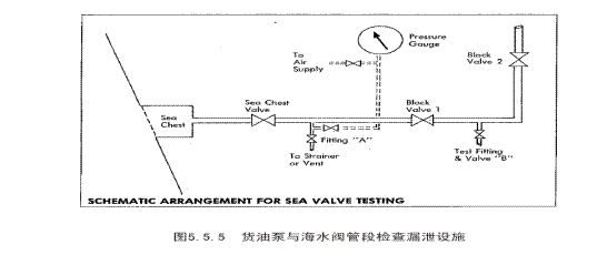
2、货泵舱海水系统,要求每舷设置通海阀,如货泵舱只设置1个通海阀,则通海阀不应与机械处所通海阀的低位吸口同一舷。(§3.4.17)
8.3.3.4.6舷外排放阀的关闭和系固:
1)舷外排放阀不使用时应关闭和系固,并设有预防意外操作的警告。如ODME
舷外排出阀(§5.5.6)
2)对于油水分离器出海阀和舱底水泵舷外排出阀,应铅封,并张贴警告,表明未经轮机长或船长许可,禁止开阀。
3)对于舱底水应急吸口阀
除SOLAS要求的2套处理舱底水装置外,船级社要求1套附加的应急舱底水处理系统,而仅用海水泵直接向舷外排放。用于此目的的应急舱底水吸口阀应容易到达和清楚标识。为防止擅自排放油或油类混合物,应确定合适的措施控制应急舷外排放阀。可采用应急舷外排放阀用有编号印记的铅封绑上,这足以证明该舷外阀未被打开过。铅封的编号可由法定文件证明,如轮机日志或油类记录本上应有对铅封的记载。但在紧急需要时,这些铅封必须能轻易拆除。如船上采用喷射泵代替其中1台污水泵,那么该喷射泵的吸入阀也应类似方法封妥。
冰区航行
8.3.3.5.1 起居处所:
(1)起居处所内应设有足够的加热设施,起居处所的加热设施应有足够的富裕量。(§3.5.6)
(2)应采取确保起居处所的进气口不被冰或雪封阻的措施。(§3.5.20)
8.3.3.5.2 管路:
(1)主推进机械和辅助机械的管路,包括日用油柜和沉淀柜的透气管,应设置避免低温引起损坏的保护设施。在系统最低的位置设置泄放考克(§3.5.7)
(2)货物舱的主透气管和辅助透气管预防冰冻措施。在系统最低的位置设置泄放考克(§3.5.9)
(3)应确保海水、压载系统和水浸透的系统应适合于船舶所航行区域。(§3.5.15)
·1尤其是如压载水设有加热系统,如是,应确认操作是满意的。
·2海水进口是否至少有1个设有加热接头,保持至少一个海水进口不会结冰。
8.3.3.5.3 甲板机械设备应设置避免低温引起损坏的保护设施。(§3.5.8)
8.3.3.5.4驾驶室:
1)驾驶室的玻璃窗应予以保护,避免遭冰冻结。(§3.5.11)
2)驾驶室不是整体围闭的,应为驾驶桥楼人员配备足够的保暖设施。(§3.5.16)
3)驾驶室两翼和船首应设置可操作的探照灯,探照灯应有合适的防冰措施。(§3.5.17)
探照灯应系固在两侧的驾驶翼桥和在船首部。每个探照灯数量、型号(包括球鼻型)和控制方式应有规定。
8.3.3.5.5 雷达应适用环境温度低于0℃工作的封闭形式,所有冰区航行的船舶应至少应配备2台雷达,其中一台为3
GHz,另1台为9
GHz。(§3.5.18)
8.3.3.5.6空气驱动的汽笛和雾笛应有加热系统。(§3.5.19)
8.3.3.5.7个人保护设备(PPE)应适合于0℃以下条件下使用。(§3.5.21)
8.3.3.5.8船上应备有接收航行、气象和环境数据的系统,包括冰况的数据和图表。
8.3.3.5.9船舶艏部是否设有探测冰况的可操纵红外线探测装置。
拖船作业设备
8.3.3.6.1闭式导缆器和拖缆桩的布置和安装
1)
拖船作业的闭式导缆器和拖缆桩应均匀布置在两舷且应有足够的水平距离(§3.6.1)
2)
首尾拖缆桩布置应使拖船产生最大回转力臂,但首尾缆桩不应过于靠近船首或船尾端(§3.6.3)
3)
拖缆桩应尽量靠近船舶强力构件处(§3.6.4)
4)
船中部的拖缆桩应便于顶推,一般应布置在货物软管支承架的后方(§3.6.5)
5)
凹入式拖缆桩,高干舷船舶,如大型液化气体运输船,拖船作业使用的拖缆桩,多采用在舷侧外板布置凹入式拖缆桩,应注意凹入式拖缆桩要尽量靠近横舱壁或强框架等强力构件处(3.6.9)
8.3.3.6.2船舶两侧拖船顶推位置,应明显标识(§3.6.2)
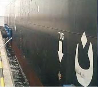
8.3.3.6.3 拖缆桩和导缆器的最小安全工作负荷标识(§3.6.8)
拖缆桩和导缆器的最小安全工作负荷应用焊接方式(点焊轮廓)清楚地标示在拖缆桩和导缆器本体上明显的位置,单位应使用小写的t,可按下表配备:
拖缆桩安全工作负荷
|
船舶载重吨
DWT
|
缆桩安全工作负荷(SWL)(t)
(“8”字形缠绕双柱形缆桩安全工作负荷)
|
缆桩公称直径(mm)
|
|
16000~50000
|
64 (32)
|
400
|
|
50000以上
|
92 (46)
|
500
|
8.3.3.6.4 船上应配备用于牵引拖船靠近船舶的引缆
(§3.6.6)
锚泊及系泊设备
8.3.4.1 系泊设备设计
1)、 系泊设备设计的原因:液货船通常是在开敞水域的突堤码头或海岛码头进行货物操作的,系泊设备不足或不适当可能引起船舶在系泊位置的过度移动或系泊缆破断,使船舶产生不适当的漂离,造成船舶或终端站或发生火灾或爆炸漂离、导致人员伤害、码头设施和船舶损坏。(4.1.1、4.1.4)
2)、 系泊设备设计的目的:建立船舶和码头的安全系固,限制船舶在系泊位置的过度移动。(4.1.4)
3)、 系泊设备的设计应考虑的因素:风、
流、潮汐、由于附近船舶通过引起的浪、波和涌、干舷和吃水的变化和冰等。(4.1.4)
4)、 从事国际航行载重量16000吨以上的液货船,系泊设备设计考虑的环境(石油行业组织采用):(4.1.5)
(1) 船舶任何方向,经受60
节风速的风力(蒲氏风力11级),并同时经受下列之一流速;
(2) 船首或船尾0
°或180°方向,经受3节的流速;或
(3) 船首或船尾100
或170°方向,经受2节的流速;或
(4) 船舶正横方向,经受最大0.75节流速。
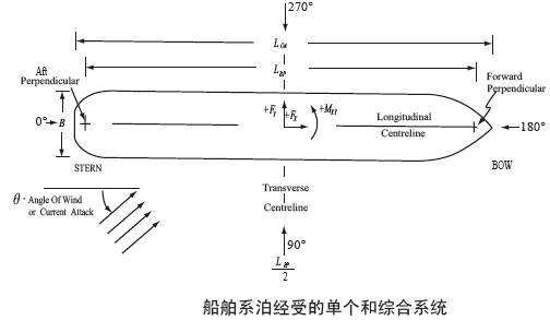
5)、 液货船系泊设备应符合OCIMF出版物《有效系泊》、《系泊设备指南》的要求,埃克森美孚(Exxon
Mobil)公司要求,除按
“系泊设备指南”、“有效系泊”衡准外,还应按公司的《海上环境、安全与质量保证衡准》(MES&QAC)进行衡准。(4.1.6、4.1.8)
6)、 系泊设备设计,可按公认标准或《石油行业组织对液货船构造与设备要求实施指南》的附录A、B、C、D为《系泊设备指南》提供的船舶系泊设备,如系泊缆索、绞缆机、系缆桩导缆器的强度的简化计算方法。(4.1.7)
7)、 普通类型的液货船,按船舶尺度在突堤码头或海岛码头系泊时,其系泊设备的设计能力,即可能承受载荷,应不小于下表所示载荷:(4.1.6)
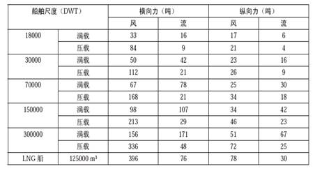
8)、 按国际航行船舶通常系泊的突堤或海岛的要求,液货船终端站典型系泊模式如下图所示:
(4.1.1)
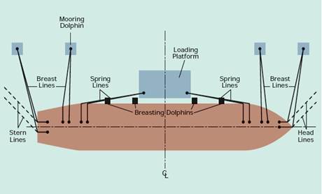
液货船终端站典型系泊模式
9)、 某些开敞水域突堤或海岛终端站的环境条件更为恶劣,其环境条件或者由于其他原因可能超过上述规定的衡准,船舶在这些突堤或海岛上终端站系泊时,船舶原来的系泊能力可能不足,船舶应借助岸上的系泊设备来补充。(4.1.3)
8.3.4.2 系泊设备的通常布置
1)、 系泊设备应满足最少系泊缆绳数量的要求。(4.2.1)
2)、 船舶首部区域(起居处所至船首系泊站),每舷至少应设置5个闭式导缆器、3个带缆桩和共计8根首缆。(4.2.2)
3)、 船舶尾部区域(起居处所至船尾系泊站),每舷至少应设置4个闭式导缆器、2个带缆桩和共计6根尾缆。(4.2.3)
4)、 船舶货物汇管中心线的前、后35m范围内,应设置至少两个闭式导缆器、系缆桩和导向至绞缆机的辅助设施,尤其是船对船驳运环境。(4.2.5)
5)、 船舶吃水超过16.5m,其货油汇管前后10m范围内,要求设置闭式导缆器。(4.2.6)
6)、 船对船货物驳运操作船舶的首、中和尾部的导缆器,应根据船舶尺度设置足够数量的闭式导缆器,建议液货船的所有导缆器均为闭式导缆器。(4.2.7 )如下图所示:
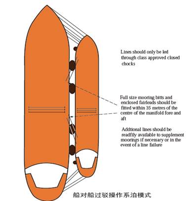
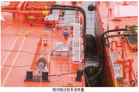
7)、 液化气体运输船,尤其是大型LNG船系泊设备的布置要求:(4.2.8)
(1)
平甲板形液化气体船,其系泊设备布置与油船、化学品船布置相类似。
(2)
球形或圆筒形液货舱的液化气体船,由于系泊设备布置原因,如系泊绞车,一般倒缆可布置 在首楼甲板和从起居甲板尾部引出。如下图:
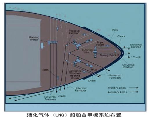
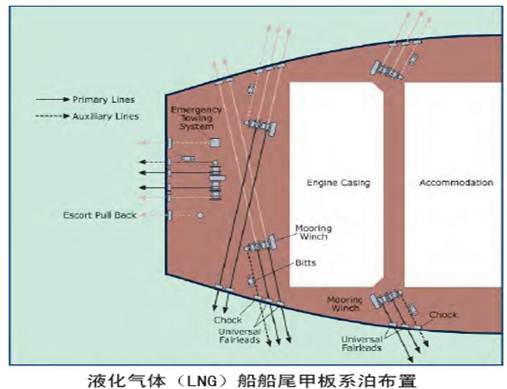
8)、 液货船按其类型和尺度的系泊模式如下图所示:(4.2.4)
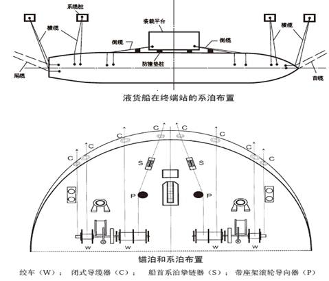
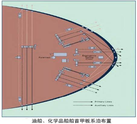
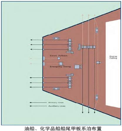
系泊缆
8.3.4.3.1系泊缆应符合的要求
1)
系泊缆的规格和结构,应符合OCIMF出版物《系泊设备指南》规定,及液货船系泊在突堤或海岛系泊的规定。(4.3.1)
2)
系泊缆,单点系泊除外,应符合油船在终端站使用系泊缆的具体规定,详见OCIMF出版物《大型油船的高模量合成纤维系泊缆使用指南》。(4.3.3)
8.3.4.3.2系泊缆的制作材料
1)
系泊缆可以采用钢质、纤维材料制成、低弹性模量材料或高模量合成纤维材料(如聚酸胺(Aramid)和聚乙烯(HMPE))(4.3.2)
2)
虽然聚丙烯的弹性模量与聚酯的弹性模量几乎相同。然而,由于材料在破断载荷时可能发生火花石油行业组织认为液货船的系泊缆,不宜采用聚丙烯材料。(4.3.4)
3)
大型液货船(载重量16000DWT以上液货船)的系泊缆,建议采用低弹性模量材料制成。(4.3.20)
8.3.4.3.3系泊缆的结构型式
1) 钢质系泊缆的结构型式很多,典型结构型式如下图所示:(4.3.10)
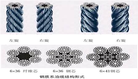
纤维材料的系泊缆结构形式有多种形式,典型结构形式如下图所示:(4.3.18)

8.3.4.3.4系泊缆的琵琶头(4.3.19)
钢质缆和纤维缆的琵琶头,可采用嵌型式、插接式和插座式连接结构,连接不应少于5花。如下图所示:
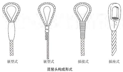 an>
an>
8.3.4.3.5系泊缆的尾缆
1)
尾缆(绳头)长度传统为11m。然而,在开敞水域的突堤码头,船舶有剧烈的运动,尾缆(绳头)长度11m可能不够。这可能会导致尾缆(绳头)立即拉断,或长时间会导致主绞车缆绳和船上和/或岸上系泊设备的疲劳破坏。(4.3.6)
2)
采用钢质材料制成的系泊缆,应采用大弹性模量的纤维材料作为尾缆。(4.3.5)
3)
船舶停靠在开敞水域突堤码头可能遭遇浪高达2m,周期超过10s的波浪,需要较长的尾缆(绳头)。船中横缆的尾缆(绳头)尤其需要增加其长度,而倒缆的尾缆(绳头)长度则不需要增加。(4.3.7)
4)
钢缆的合成纤维尾缆(绳头)通常至少18个月应更换,除非根据使用经验或检查结果,经正规训练的检查人员应用技能评估方法,判定可超过或低于该期限更换。应该保存尾缆使用的记录,记录的内容包括使用的时间和检查的结果,当其剩余强度降到初始最小破断负荷的60%时应该更换尾缆。上述18个月是基于船舶营运的实际平均使用时间。船上应该有对尾缆检查/评估程序等关键内容(需要记录)。应该确认缆绳的检查/评估的培训是否有效开展。(4.3.11、4.3.12)
8.3.4.3.6系泊缆与尾缆的连接
1)钢缆与纤维尾缆应采用通士伯(Tonsberg)或曼德尔(Mandal)型卸扣连接。如下图所示:(4.3.13)
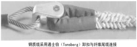
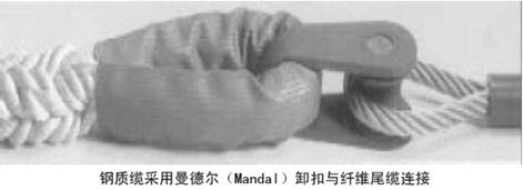
2)纤维缆与纤维缆的连接建议采用套接连接,如下图所示。(4.3.14)

3)钢质缆与合成纤维尾缆连接,也可以采用博士(Boss)卸扣连接,如下图所示。(4.3.15)
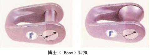
8.3.4.3.7系泊缆的额外配备
1)为货物操作安全,尤其是船对船过驳操作的船舶。在汇管区域应至少配备4根直径20mm、长度20m的纤维缆,供货物软管与货物汇管连接时作为限制货物软管的操作绳,以及4根合成材料制成的引缆。(4.3.16)
船首、船尾至少各配备2条钢缆,每条至少直径为30mm,长度为100m。(4.3.17)
8.3.4.3.8系泊缆的最小破断负荷
1) 系泊缆的最小破断负荷与材料和结构有密切关系,下面为 6X36钢质缆绳公认的最小破断负荷(MBL):(4.3.21)
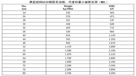
由于纤维材料,如合成纤维或尼龙,湿态时其破断强度下降,故采用合成纤维做尾缆绳时,其最小破断负荷(MBL)应为钢缆最小破断负荷(MBL)的125%。尼龙尾缆的最小破断负荷(MBL)应为钢缆最小破断负荷(MBL)的137%。(4.3.9)
8.3.4.3.9系泊缆的总能力要求(4.2.23)
1) 载重量小于46000t的船舶,如下表所示:
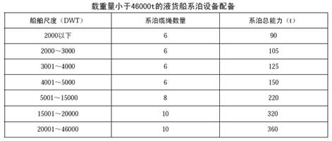
2) 载重量大于46000t的船舶
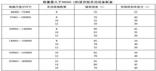
系缆桩/系船柱
8.3.4.4.1缆桩/系船柱的布置和安装
1)
系缆桩应适合于根据船舶尺度要求的系泊总能力配备系泊设备,系泊设备应两舷均匀分布(4.4.1)
2)
所有系缆桩/系缆桩,应焊接在船舶每舷的甲板上及要求设置的位置上。(4.4.2)
3)
对于高干舷船舶,如液化天然气船(LNG),系缆桩可以安装在靠近船舷(4.4.3)
4)
每舷货物汇管前和后端,应设置直径不小于300mm两柱型系缆桩(4.4.10)
5)
具有挥发气体回收系统,应设有与汇管直线或接近直线的“十字”形系缆桩,用于系固VRS软管的悬挂链条。(4.4.12)
6)
挥发气体回收系统的汇管到封闭式系缆孔连线上,应设有2
个悬吊和紧固16”货物软管缆绳的甲板眼板。(4.4.13)
7)
每个双柱型系缆桩和十字形系缆桩附近,应设置挚缆器(Line
Stopper)。(4.4.9)
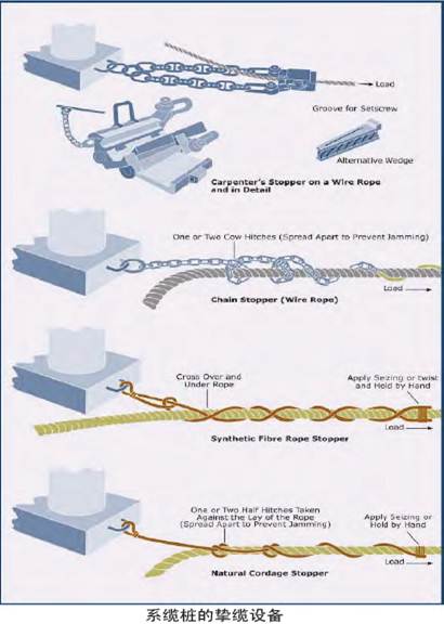
8)
溢油柜端部甲板应设置“十字”形系缆桩。“十字”形系缆桩布置为:(§3.3.7)
(1)
“十字”形系缆桩中心线与溢油柜首端部距离不小于1200mm。
(2)
(2) “十字”形带缆桩中心线与溢油柜侧面端部距离不小于300mm。
(3)
(3) “十字”形系缆桩长度不小于400mm。
9)
船对船过驳操作时,货物汇管处至少应设置为横缆的系缆桩,两个闭式导缆器、双柱形系缆桩和绞缆机辅助设施。(§3.2.10)
10)
系缆桩应与甲板焊接连接。(4.6.12)
8.3.4.4.2系缆桩/系船柱的形式
1)
系缆桩形式,一般有单柱形缆桩(Single
Bollard)、双形柱系缆桩(Double
Bollard)和“十字”形系缆桩(Cruciform
Bollard),如下图所示。(4.4.4)
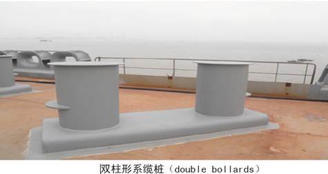
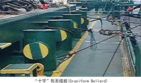
2)
船上设置船舶系泊用的系缆柱(bitt),包括用于应急脱离缆的系缆桩,应为双柱形系缆桩(4.4.6)
3)
双柱型系缆桩的直径,一般不应小于系泊缆直径的10倍,至少应大于300mm。(4.4.7)
4)
双柱形系缆桩承受缆绳载荷能力,一般为“十字”形系缆桩承受缆绳载荷的2倍。(4.4.5)
5)
每舷货物汇管甲板中心线的甲板上,应为“十字”形系缆桩。“十字”形系缆桩的高度应在甲板以上至少为600mm。这些带缆桩应安装于每对货油集管间的中间位置,在其工作平台和舷侧间留有最大的通道,同时在带缆桩和溢油柜之间留有足够的空间(约300mm)
,以便安全操作,如下图所示。(4.4.14)
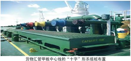
6)
载重量160000吨以上船舶,所有闭式导缆器处设置用于系泊操作柱形系缆桩应为双柱形系缆桩,双柱形系缆桩的直径应不小于550mm。(§3.3.9)
3.4.4.3 系缆桩/系船柱的安全工作负荷
1) 系缆桩/系船柱的安全工作负荷应能承受允许使用系泊钢缆或系泊缆绳承受的任何载荷。采用“八字”形靠近系缆桩附近的最大负荷。系缆桩的全工作负荷,任何时候不应小于系泊缆最小破断负荷(MBL)。传统设计观念,系缆桩的安全工作负荷一般为系泊缆最小破断负荷(MBL)的2倍。(4.4.8)
2) “十字”形系缆桩工作负荷至少为:(4.4.11)
(1) 载重量60000t以下为25t。
(2) 载重量60000t及以上为40t。
3.4.5导缆器:
3.4.5.1导缆器的布置和安装(注意《指南》的《附录C系泊设备与船体结构加强》
8.3.4.5.2导缆器的形式
有开式导缆器、闭式导缆器、巴拿马导缆器、带座架滚轮导缆器、万向滚柱导缆器或井字型导缆器,如下图所示:(4.5.7)
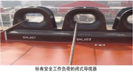
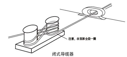
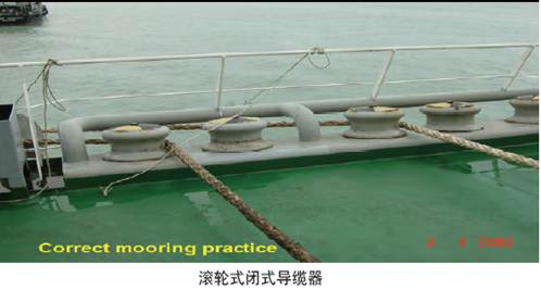
8.3.4.5.3导览器符合的要求
1)液货船的所有导缆器应采用闭式导缆器。(4.5.1)
2)为系泊安全,每个闭式导缆器只允许通过1根系泊缆。(4.5.2)
3)导缆器的开口净尺寸至少为400mm x 250mm。表面最小曲率半径为180mm。(4.5.3)
8.3.4.5.4导缆器工作负荷
1)导缆器工作负荷,根据船舶尺度和机器工作条件而定。然而,导缆器工作负荷无论如何不能小于通过缆绳的最小破断负荷(MBL)。(4.5.5)
2)货物操作用的导缆器工作负荷,根据船舶尺度一般应不小于下值:(4.5.6)
a.
载重量60000t以下液货船为25t;
b. 载重量60000t及以上液货船为40t。
8.3.4.5.5货物减载装置,载重量175000t以上液货船,应设置货物减载装置(Lightening Arrangements)(4.5.8)
1)船舶两舷,船中前后35m应设置2个净开口尺寸为500mm × 400mm的重型闭式导缆器,至少应在船舶右舷设置重型闭式导缆器。
2)位于重型闭式导缆器处,应设置柱直径为550mm的双柱型系缆桩。
3)为避免货物减载操作期间,由于干舷巨大变化造成困难,系泊期间使用的导缆器均应为闭式导缆器。终端站一般设置快速释放装置,如下图所示:
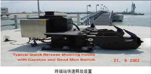 an>
an>
绞缆机(关于系泊绞车的刹车力试验及性能标准可参见《指南》的《附录D 系 泊 绞 车》)
8.3.4.6.1绞缆机的布置安装(注意《指南》的《附录C 系泊设备与船体结构加强》)
1)
系泊设备布置,缆桩与导缆器之间的最小距离为1.8m。(4.6.9)
2)
绞缆机应布置成使绞车卷筒与最近的导缆器之间的最小距离,应使移动角不超过1.5°。(4.6.10)
3)
绞缆机的安装:绞缆机底座应与甲板焊接连接。(4.6.12)
8.3.4.6.2绞缆机的型式
1)
绞缆机有张力式绞缆机和自卷式绞缆机。(4.6.1)
2)
自卷式绞缆机有整体式和分隔式两种。(4.6.3)
3)
自动调节张力式绞缆机,具有自动松开或自动绞进系泊缆,一般在船舶停靠后,不允许使用自卷绞缆机。(4.6.2)
4)
液货船靠泊期间一般不允许使用恒张力绞缆机。(4.6.7)
8.3.4.6.3 绞缆机的安全工作负荷,绞缆机安全工作负荷(SWL)按公认标准,应大于系泊缆最低破断负荷(MBL)。(4.6.4)
8.3.4.6.4绞缆机的刹车
1)
系泊绞缆机应带有刹车装置,刹车装置一般有液压刹车和手动刹车装置。(6.114)
2)
系泊绞缆机刹车能力,一般为系泊缆最低破断负荷(MBL)的80%,在实际使用中,系泊绞缆机刹车能力调整为系泊缆最低破断负荷(MBL)的60%。(4.6.5)
3)
初始时系泊绞缆机刹车能力应调整为系泊缆最低破断负荷的60%。实际工作系泊绞缆机刹车带在使用中会发生磨耗,建议新系泊绞缆机刹车能力应设计成系泊缆绳最低破断负荷的80%,在实际使用中系泊绞缆机刹车力调整降低至60%。(4.6.6)
4)
绞车刹车力测试报告。
8.3.4.6.5 系泊绞缆机至少应有举起15t的能力,其贮缆滚筒应有贮存直径80mm,长度150m的缆绳的能力(4.6.8,4.8.3)
8.3.4.7系泊程序和系泊设备状态
1)系泊布置合理,相同方向的系泊缆具有相同的结构和尺度
2)系缆紧固在带缆桩上,盘绕方向正确
3)所有受力系缆正确卷绕在滚筒上
4)所有受力系缆系固在制动器上,绞缆机的滚筒与齿轮已脱开
5)分离式滚筒绞缆机,所有系缆在每个滚筒的拉力端上已卷紧且绕缆不多于1层
6)钢缆与尾缆配有合适的通士伯(Tonsberg)、曼德尔(Mandal)或博士(Boss)连接卸扣,且安装正确
7) 系缆整齐存放,使绊倒危险最小,系泊区域清洁无障碍物
8) 绞缆机刹车是开启的。
9) 绞缆机处于满意状况
10)绞缆机底座处于满意状况
11)刹车带、刹车鼓和销钉外观处于满意状况
12)位于气体危险区域的电动绞缆机防爆等级为Ex’d’
级
13)电动绞缆机已进行绝缘试验,其记录结果保存在船上
14)蒸汽动力驱动的绞缆机,其蒸汽箱以及蒸汽箱与绞缆机的连接座处于满意状况,无腐蚀或临时修理
15)系泊缆、系泊缆尾缆处于满意状况
16)基座(“井”形柱式)导缆器、滚轮导缆器及其他滚轮的润滑良好并能自由转动,缆桩和导缆孔是无凹槽
17)系泊设备标有其安全工作负荷(SWL)
18)电气设备绝缘电阻最低为5兆欧。
19)系泊缆具有足够强度,即其强度降低不大于原最小破断负荷(MBL)的10%,眼环插接不少于5花,任何1股的金属丝不能有3根断裂,10倍直径长度范围内不超过5处断裂。
单点系泊
(SPM)
3.4.8.1 单点系泊设备的布置
1)可能靠泊单点系泊装置操作的液货船,应根据船舶尺度配备单点系泊设备。(4.7.1)
2)现有船,即2009年以前交付使用的船舶,建议采用每个首挚链器使用的带基座的滚轮导向器数量不能超过1个,且引缆方向变换角度应尽量最小。单点系泊设备,包括导缆器、挚链器、带基座滚轮导向器和绞缆机,应尽量布置成直线。如不能成直线,则布置成不能多于1个转角,而转角不能为直角,转角角度一般不小于120°,有的要求转角角度不小于150°。(4.8.7)
3)液货船2009年或以后交付使用的,其单点系泊设备,建议使用绞缆机贮缆滚筒,使引缆的回收直接从首导缆器引导到首挚链器,不需要使用基座的滚轮导向器。液货船单点系泊设备相关位置应直接引导成直接至绞缆机的贮缆滚筒,认为是操作引缆最安全和最有效率的装置。然而,不是所有新设计的系泊装置都可以允许将缆直接送至绞缆机的贮缆滚筒。可以考虑设置带基座的滚轮导向器的数量和位置,但是,设计时应从安全方面考虑和防止系泊人员被鞭绳引起的伤害危险。(4.8.1)
4)遥控操作绞缆机贮缆滚筒,可能需要给绞缆机操作者提供额外的保护,以防止系泊人员被鞭绳引起的伤害危险。(4.8.2)
5)单点系泊应设立独立绞缆机,尽量避免使用其他绞缆机的端部滚筒。(4.8.3)
6)用于单点系泊的导缆器及其布置(4.8.4)
(1)
设1个单点系泊设备的导缆器,应布置在船舶中心线上。
(2)
设2个单点系泊设备的导缆器,应布置成它们间的距离大于2m,但不超过3m。o
(3)
导缆器尺度不应小于600mm×450mm。
7)用于单点系泊的挚链器及其布置:(4.8.5)
(1)
挚链器系泊能力,挚链器应永久性标示其系泊能力,且持有有效证书。
(2)
挚链器应位于首导缆器内侧的距离为2.7m~3.7m,不管船舶尺度如何。
(3)
根据绞车布置适当的带基座滚轮导向器。
(4)
任何情况下,引缆不允许通过1个以上带基座滚轮导向绞车。
(5)设有带基座滚轮导向器,应位于首挚链器后方,距首挚链器的最小距离无论如何不应小于4.5m。
8)用于单点系泊的绞缆机规格与配备(4.8.6)
(1)
绞缆机有与锚机通用的也有独立设置的,其贮缆卷筒(储缆器)应能贮存直径80mm,长度150m的引缆。
(2)
安装单点系泊设备的挚链器、带基座滚轮导向器和绞缆机的甲板结构,应进行相应加强。
(3)绞缆机应符合OCIMF《系泊设备指南》附录A。
(4)单点系泊每个船首挚链器应配备1个绞缆机,绞缆机提升能力不应小于15t。(4.7.6)
9)单点系泊设备的船舶,船尾应设有单点系泊期间为护卫和后拖拖船使用的设施,如下图所示。(4.8.8)
(1)
导缆器(chock/fairlead)和强力点(strong point):
① 载重量20000~50000t船舶,导缆器最小安全工作负荷(SWL)为100t,强力点当使用单眼环或单索环时,其最小安全工作负荷(SWL)为100t。
② 载重量50000t以上船舶,其最小安全工作负荷(SWL)为200t,强力点当使用单眼环或单索环时,其最小安全工作负荷(SWL)为200t。
(2)
护卫和后拖的重要组件的安全系数应为相应安全工作负荷的2倍。
(3)
导缆器(chock/fairlead)应尽量布置在船舶中心线的尾部。导缆器应为椭圆形。
(4)
强力点或拖缆连接点与导缆器应在船舶纵向成直线,它们间不应有任何障碍物。
(5)
强力点直径不应小于600mm,距甲板高度不应小于300mm。
(6)
强力点与导缆器的距离不应小于4m。如载重量50000t以下的船有困难,强力点与导缆器的距离可适当减少,但应确保拖缆连接器在导缆器内侧。
(7)
护卫和后拖设施的所有属具应清晰表明其安全工作负荷(SWL)。注意:安全工作负荷(SWL)应采用吨,应采用符号“t”来表示,不允许采用其他符号表示。
(8)
护卫和后拖拖船设施的固定设施,如强力点、导缆器、基座应急船上的支承结构应考虑其可能承受的载荷
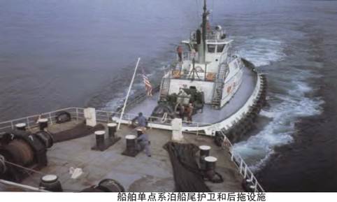
10) 按SOLASII-1/3-4要求设置在尾部的应急拖带装置(ETA),可用于单点系泊的护卫和后拖拖船设施,而用于双重目的设备,应满足船舶单点系泊期间的船尾护卫和后拖拖船和单点系泊设施的要求。(4.8.9)
11) 某些石油公司,如雪佛龙、BP和壳牌,采用更高标准单点系泊设备,对100000 DWT的液货船,要求设置2个单点系泊设备。(4.7.9)
12) 单点系泊设备的典型布置:如下图所示。(4.7.7)
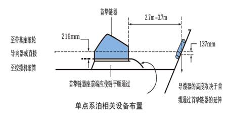
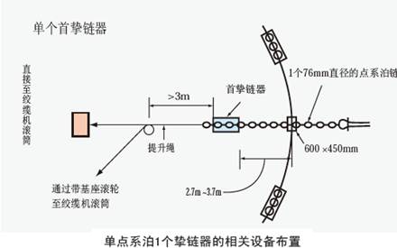
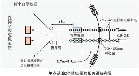
13) 单点系泊与普通系泊模式如下图:(4.7.10)
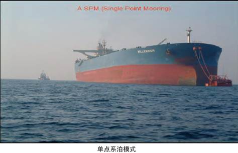
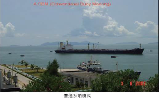
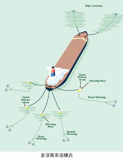
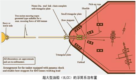
14) 检查单点系泊绞车、船首挚链器、导览器和防擦链的安装,注意《指南》的《附录C 所属系泊设备与船体结构加强》。
an>
8.3.4.8.2单点系泊设备符合的要求
1)
液货船2009年或以后交付使用的,单点系泊设备的船首止链器的数量和能力应符合下列规定:(4.7.2)
(1)100000 DWT以下:
1个
200 吨安全工作负荷(SWL);
(2)100000~175000
DWT:
2个
250 吨安全工作负荷(SWL);
(3)175000 DWT 以上:
2个350
吨安全工作负荷(SWL)。
2)
鼓励2009年以前交付使用的液货船,其单点系泊设备数量和能力在合理和可行范围内尽量考虑与新造船相适应的要求,也可以继续使用船舶按现有要求配备的首挚链器。(4.7.3)
3)
所有船的单点系泊的首挚链器,如为液压挚链器,应设置防止意外释防措施。(4.7.4)
4)
所有船的单点系泊设备的首挚链器,至少应能容纳76mm防擦链。(4.7.5)
5)
挚链器的尺寸,数量和型号应满足OCIMF指南规定的船舶尺度来确定。(4.7.8)
8.3.4.8.3如船舶安装液压首制链器,采取了防止意外释放的保险措施。
8.3.4.8.4单点系泊(SPM)和相关设备处于满意状态。
8.3.4.8.6单点系泊储缆筒,具有足够的储存能力。
8.3.4.8.7护卫和后拖拖船使用的设施处于满意状态。
3.4.9应急拖带装置
3.4.9.1应急拖带绞车、挚链器、导览器和防擦链的安装。
8.3.4.9.2首和尾应急拖带装置处于随时可以使用的状态。
8.3.4.9.4应急拖带装置使用程序,或应急拖带程序。
8.3.4.9.5驾驶室和装置处张贴应急拖带装置布置图。
8.3.4.9.6急拖带设备标有永久性安全工作负荷。
8.3.4.10应急拖离缆(火灾拖离缆)
1)应急拖离缆(火灾拖离缆)的布置,特别应注意符合港口当局的要求和OCIMF关于按船舶尺度配备规定(4.9.1、4.9.2)
2)应急拖离缆(火灾拖离缆)的结构和材料,特别注意符合OCIMF的要求(4.9.2)
3)应急拖离缆(火灾拖离缆)的最小长度和强度(4.9.3)
4)应急拖离缆(火灾拖离缆)随时处于可用状态(4.9.1)
5) 应急拖离缆(火灾拖离缆)布置图,展示在驾驶室内。(4.9.2)an>
8.3.4.11海上船船过驳的系泊要求和操作手册
1)
在船对船(STS)驳运操作期间,建议所有导缆孔是封闭式的。
2)
这些导缆孔应有足够的强度以承受系泊载荷,其孔径应足够大,从而能轻松地穿过大尺度的系泊缆绳。(加上缆绳和连接卸克)。(STS指南9.3)
3)
承受强缆全部强度的封闭式导缆孔和带缆桩,应布置在汇管出口前后不超过35m处。(STS指南9.3)
4)
所有液货船两舷,建议安装配备足够强度的带缆桩。
(STS指南9.3)
5)
另外,建议提供系固碰垫的紧固索。
(STS指南9.3)
6)
对于液化气体运输船,应参考OCIMF/ICS船对船(STS)过驳操作指南(液化气体)的建议。
锚泊设备:
e: 10.5pt;">
8.3.4.12.1检查锚机安装和布置合符图纸要求(注意《指南》的《附录C
系泊设备与船体结构加强》)。
8.3.4.12.3按说明书要求,试验锚机机刹车力负荷。
8.3.4.12.4锚机、锚、闸刀和锚链处于满意状态并能有效工作。
8.3.4.12.5使用的锚泊设备处于锁定状态,不用的锚机处于刹车锁紧状态。
8.3.4.12.6弃链器装置位于锚链舱外部,附近无障碍。
8.3.4.12.6弃链器装置位于锚链舱外部,附近无障碍。
防止船舶造成污染
8.3.5.1 船舶响应计划
应注意,液货船的“船上油污应急计划”(SOPEP)或“船上有毒液体物质海洋污染应急计划”(SMPEP)和 “船舶应急响应计划”(ERS)应为船上工作语言、英文。
甲板上防止货物操作溢油污染设施与布置
8.3.5.2.1液货船甲板边缘应设置连续档板和横向挡板,检查连续挡板的布置和高度满足要求。(§5.2.1-5.2.3)
1)应设置使甲板溢油保持在甲板上远离起居处所和服务处所的设施,这可以通过设置至少高度为300mm的从船一舷延伸至另一舷固定连续围板构成的设施。对尾部装货装置应给予特别考虑。
2)有些石油公司,如埃克森美孚,要求船舶货物区域后端的甲板边缘的连续挡板高度为:
(1) 大于100000 DWT的油船和危险化学品船,船首甲板边缘连续档板高度,应至少从船首250mm,逐渐过渡至货物舱后端与后端横向档板相连接,后端横向档板高度为400mm。
(2) 小于100000 DWT的油船和危险化学品船,船首甲板边缘连续档板高度,应至少从船首150mm,逐渐过渡至货物舱后端与后端横向档板相连接,后端横向档板高度300mm。
3)围板的第2个目的是发生溢油时,在主甲板后部提供储存油类,给船员有足够时间处理和防止油入海。
8.3.5.2.2甲板边缘应设置泄水孔
1)甲板边缘的连续档板,应设置足够数量和尺寸的泄水孔。泄水孔的排水能力应满足国际载重线公约(LLC)的要求。(§5.2.3)
2)甲板边缘设置的泄水孔应配备有效的机械式孔塞或等效设施。(§5.2.5)
对于气体运输船,只有其在加装燃料,或载运MARPOL附则1所述货物时,船上货物区域的甲板排水孔才要求堵塞。
8.3.5.2.3甲板边缘设置的连续档板与横向档板在甲板上形成聚集油类储存槽,相关储存槽应设置处理设施,以处理槽内溢油。这些处理设施应为固定式驳运系统,将甲板溢油驳入污油水舱。如采用移动式泵,管路应为固定式的,且有安全操作程序。但应注意下列问题:(§5.2.4、5.2.7)
1) 应使用无火花溢油驳运泵,溢油驳运泵应能妥善安装。(§5.2.7
(1))
可移动式防污溢油泵也应妥善安置,防止在操作时因移动而损坏。
2) 检查相关的跨接接地,以防止静电荷(§5.2.7
(1))
例如:如使用可移动式防污溢油泵,该泵必须和船体跨接以防止对地放电,跨接可以用外接导线,也可以利用泵的排放软管法兰连接达到接地效果,例如用法兰附件连接船体附件。
3)当提供可移动式防污溢油泵和排出是引向货油舱,就必须有适当的固定式接头。不允许把处理溢油将防污溢油泵的软管通过液货舱开口,如通过观察口引入货油舱。
4) 溢油驳运至污油水舱的甲板泄放阀和U形管的设置:
----设有惰性气体船舶:如设计甲板泄放阀,该阀应设置带有环形密封装置,一般来说,船上用U形管的较多。(§5.2.7
(2))
★ 如泄放阀安装在主甲板尾部,应确认处理溢油时只要打开阀就能使油流入液货舱内。当液货舱内压力过大,阀打开会导致压力的释放从而引起更糟糕情况,应有适当的防止设施。
★ 泄放至液货舱管路上安装U形管能使液货舱压力不必预先减压溢油安全释放,而应根据U形管上的液位所产生足能阻止舱内挥发气体回流压力。
----未设惰性气体船舶:为防止产生静电或静电雾,甲板泄放阀引致污油水舱内的泄放管应延伸至舱底。(§5.2.7
(3))
5)溢油驳运至污油水舱操作注意事项:
★ 液货舱的空挡高度,可能会影响从甲板上排泄溢油流进液货舱的能力,特别是当液货舱已满舱和船舶尾倾。如无法有效排泄溢油,或者需要预先释放压力,那么就应有其他能够立刻清除溢油的方法。
★ 需要认识到船舶中垂,溢油会聚集在船的中部,假如是首倾,溢油则聚集在首部。溢油设备和处理设施的布置应能处理这些状况。
8.3.5.2.4对小型船舶,如甲板上溢油排放入甲板下方的污油水舱不可行时,可设置容积不小于2m3的甲板密封容器,作为收集甲板溢油容器。化学品船常采用密封的容器(deck tank)。(§5.2.7 (8))
注意:相关的甲板密封容器应为固定式的。
8.3.5.2.5检查下列位置的溢油收集容器或溢油收集槽(spill tank)的容积和尺寸:在该方面的规定上,不同的组织和港口国有不同的要求,如果航行美国水域,还应注意US 33 CFR, Part 155.310的要求。使用较高的标准。
1)溢油收集槽应为固定式,并设有泄放和迅速有效清除溢油的设施。
2)货物汇管、加油汇管和货物挥发气回收汇管法兰下方的集油槽(§5.2.8);尺度要求如下:
* 长度:沿船长方向设置,应包含货物汇管、燃油加油汇管的外侧法兰中心线向前和向后端。对于油气回收系统,则应包含油气回收汇管的外侧法兰中心线向前和向后端;
* 宽度:至少为1.8m,且应在异径器(异径连接器)外侧法兰外1.2m;
* 高度:至少为300mm;
* 垂直位置,溢油收集槽上面的工作台,应在在异径器(异径连接器)外侧法兰中心线以下900mm。
3)所有燃油舱,燃油日用柜、沉淀柜、贮存柜和滑油柜和其他易燃液体柜、液压油舱的透气管甲板出口处, (§5.2.9、5.2.10)
溢油收集槽的高度,不应小于300mm,但其高度不能达到透气管(空气管)的开口附近。一般在开口以下不小于200mm。(§5.2.11、5.2.12)
容积:
(1)载重量大于75000 DWT(Aframax)船舶的溢油收集槽,至少为1桶(约0.15m3),
(2)载重量小于75000 DWT船舶, 至少为0.5桶(约0.075m3)。
4)甲板上所有液压机械,加热盘管管汇和其他甲板机械周围,溢油储存容器围栏高度通常不应小于150mm。(§5.2.14)
8.3.5.2.6首楼和其他处所,应设有足够的固定式处理含有污水的设施。(§5.2.18)
8.3.5.2.7核查机舱油水分离器的电源开关是否设在驾驶台,这种设计是为了防止在港口和MARPOL公约所规定的特殊区域内或未经值班驾驶员的许可的情况下,油水分离器由于误动作而起动。
8.3.5.2.8除了Marpol
公约附则I的12A要求的燃油舱双壳保护外,EXXONMOBIL强烈建议含有燃油、滑油或其他含有污染物质的舱柜能满足双壳保护的要求。
8.3.5.2.9通过通岸接头向岸上排放油渣或舱底水的位置(包括机舱、泵舱内的舱底水驳运),核查设有应急停止油渣驳运泵和舱底水驳运泵的设施。对于泵舱舱底水的驳运,相关应急停止装置至少应在(泵房内)上甲板上操作。
8.3.5.2.10确认甲板上的液压软管每5年更换一次,公司应有相应的检查、试验和更换的体系文件。
防止货物污染的布置
8.3.5.3.1每个货油舱后部应设置适当数量的浸迹式测量装置,以检查货油舱清洗的有效性。(§5.3.2)
8.3.5.3.2所有与货物舱相邻的压载舱,在露天甲板上应设有压载水舱取样与观察装置。检查压载水舱取样与观察装置的布置和尺寸满足要求。(§5.3.2、5.4.5)
注意:气体运输船的压载舱,只有燃油管路在压载舱内通过或压载舱与燃油舱比邻,才需要取样和视察检查。
8.3.5.3.3货物舱需装载附加压载水,应符合下列规定:(§5.3.6)
1)应通过专用压载泵、管路系统和辅助设施,采用跨越舱顶充装打入压载水。货物舱顶充装系统的注入管应延伸至舱底。
2)压载系统与货油系统应采取物理隔离装置。上述隔离装置通常采用两个隔离阀,1个截止阀和1个止回阀,而止回阀通常应安装在货物舱侧,隔离装置应有定期压力检查和试验程序,其试验结果记录应保存在船上。该物理隔离也可采用盲通法兰(眼镜法兰)或可拆短管。
8.3.5.3.4随时可用的清除溢油污染设备。(§5.3.7、5.3.8)
压载水管理
8.3.5.4.1应注意,液货船的《压载水管理计划》应为中、英文。(§5.4.1)
机舱与舵机舱防污设施
8.3.5.5.1检查机器处所根据SOLASII-1/35-1设置舱底水系统舷旁排放口的阀,船舶在正常情况下(船体和设备未发生破损)应给予关闭,并用有数字编号铅封。并张贴“此阀未经许可严禁操作”的特别警告。(§5.6.3、5.6.4)
8.3.5.5.2检查机器处所设的应急舱底水吸口,应急舱底水吸口的操纵阀,在正常情况,应给予关闭并铅封,阀盘应明显标识“此阀未经许可严禁操作”的特别警告。(§5.6.6)
检验中应注意:
1)SOLAS要求,卫生水泵、压载泵和通用泵,只要其与舱底泵系统有必要的连接,可接受作为独立的动力舱底泵。虽然无特别说明,SOLAS的要求是允许在应急情况下将舱底水向舷外排放,MARPOL附则I/4也允许如此。
2)应急舱底水舷外排出口,不得用于处理机舱日常聚集的舱底水。
3)应检查船舶舷侧排放阀和排放管附件,是否有油类污染。
4)除SOLAS要求的2套处理舱底水装置外,船级社要求1套附加的应急舱底水处理系统,而仅用海水泵直接向舷外排放。用于此目的的应急舱底水吸口阀应容易到达和清楚标识。为防止擅自排放油或油类混合物,应确定合适的措施控制应急舷外排放阀。可采用应急舷外排放阀用有编号印记的铅封绑上,这足以证明该舷外阀未被打开过。铅封的编号可由法定文件证明,如轮机日志或油类记录本上应有对铅封的记载。但在紧急需要时,这些铅封必须能轻易拆除。
5)如船上采用喷射泵代替其中1台污水泵,那么该喷射泵的吸入阀也应类似方法封妥。
8.3.5.5.3机器处所应设置舱底水高水位报警装置。建议此高水位报警不能触发按SOLAS
II-1/35-1规定设置的舱底水系统的舱底水泵运行。(§5.6.7)
8.3.5.5.4船上机器处所设置的油渣泵,除排至甲板上的标准排放接头外,不允许有任何直接排放舷外的接头。(§5.6.10)
8.3.5.6 检查机器处所舱底水辅助排放系统:应经船级社审批。
1)机器处所含油污水排入污油水舱是在特殊情况,如船舶非航行期间、或机器处所正常舱底水处理装置临时出现故障时,机舱含油污水或油渣进行紧急排放的辅助排放系统。
2)按图纸核查船舶机器处所舱底水辅助排放系统的布置和安装(§5.7.1)
3)机器处所舱底水辅助排放系统应有操作程序(§5.7.4)
4)检查系统是否有发生火灾和污染的可能:具体参见《指南》5.7.3的技术要求。(§5.7.3)
8.3.5.7 检查泵舱舱底积聚污油水的应急处理设施 (ISGOTT 10.11.2)
某些油船,未安装有效的排放系统,为满足运输某些特有产品的需求,管线内最后残余物是排入泵舱污水阱的,这是不安全的行为,应采取有效手段防止易燃气体和挥发性物质排入舱底水。
当管路曾被作为压载水系统使用,而在排水结束后又只能将剩余的水放进泵舱,那须特别谨慎管线中没有石油制品。
8.3.5.8 垃圾管理
1)核查垃圾的存放位置,确保垃圾对邻近处所不构成潜在危险。
2)应特别考虑被称为“特殊废料”的垃圾的存放,如电池、传感器和荧光管,确保只有兼容的材料才存放在一起。ICS出版物《垃圾管理计划准备指南》,提供如何符合MARPOL73/78附则V的信息。
(ISGOTT 12.4.2)
8.3.5.9 其他污染的控制
主要只下列有其他有关船旗国和港口国主管机关要求的特殊防污染控制要求,如
(1)欧盟对停靠其港口的船舶关于低硫燃油的特别要求;
(2)噪声等级要求;
等等
防止火灾和爆炸
控制易燃气体——防止易燃气体过量积聚措施
8.3.6.1.1惰性气体系统:检验要求同消防规则,但配置要求高于消防规则。
1、配置要求:(见指南§6.1.1、6.1.2、6.1.3)
1)装运闪点不超过60℃货油的货物舱,或装运闪点60℃以上货油而其操作温度超过货油闪点以下小于10℃的货物舱,应设有固定式惰性气体系统。
2)装运闪点60℃以下货油的货物舱,或装运闪点60℃以上货油而货物操作温度超过其闪点或与其闪点之差小于10℃时,未设惰性气体系统的货物舱,应设置与洗舱机联锁的通风系统,确保洗舱期间保持有效的连续通风。
3)装运货油闪点60℃以上的货物舱,当洗舱机单个排量大于60m3/h,或单舱洗舱机总排量大于180m3/h时,应设置惰性气体系统。
2、特别要求
1)设有固定式惰性气体系统船舶,所有双壳边压载舱的透气系统应设置固定式易燃气体探测系统,双壳边压载处所应设置固定式惰性气体充气管系和用空气驱气的设施。在货物区域甲板上,应设有为双壳边压载处所供给惰性气体的接入管。(§6.2.1(3)、6.2.2、6.5.6)
2)未设惰性气体系统的货物舱,货物舱内的所有设备,如液位测量设备、取样设备、温度测量设备等,应跨接或有效接地或采取其他有效预防静电措施。跨接和接地方法是各导体之间采用金属材料连接。(§6.3.2)
3)载运闪点不超过60℃货物的货油舱,如未设惰性气体系统保护,不应设置固定式洗舱系统(§6.3.3)
8.3.6.1.2固定式易燃气体和火灾探测系统
1)与货油舱相邻的留空处所、压载处所或其他处所,应设置固定式易燃气体探测系统对易燃气体浓度进行探测。(§6.2.2)
2)厨房、货物样品储存处所,应设置火灾探测装置(感温或感烟)。(§6.5.2)
8.3.6.1.3设置固定式惰性气体系统的船舶,应设置2台固定式和移动式氧气测量设施。
抑制点火源
8.3.6.2.1载运闪点不超过60℃货物,主货油泵禁止使用往复泵。载运闪点超过60℃货物,建议其货物系统尽量避免使用往复泵。(§6.3.1)
8.3.6.2.2吸烟室:
吸烟室仅允许设置在起居处所内,且吸烟室不应有直接通向外部的门、开口和其他开口。吸烟室应提供安全火柴或固定式(车载型)电子点烟器。禁止使用所有机械式打火机和具有电点火源的移动式打火机。(§6.3.8、6.3.9、6.3.10)
8.3.6.2.3液货船限制使用移动式炊具和厨具。船舶靠泊或货物操作期间,禁止使用移动式炊具和厨具、明火的其他炊具厨具。(§6.3.6、6.3.7)
8.3.6.2.4防爆安全型设备(§6.3.11、6.3.12、6.3.13)
---- 用于易燃气体环境使用的手电筒,
(§6.3.11)
---- 布置在货物区域救生圈的自亮浮灯,
(§6.3.12)
---- 超高频/甚高频
(UHF/VHF) 移动式无线电对讲机,
(§6.3.13)
---- 布置在货物区域的救生筏的自亮灯应为本质安全型。(§8.13.4)
8.3.6.2.5应禁止使用窗式空调。
如现有船上使用窗式空调,应严格管理,尤其是货物操作期间或船舶停靠期间应禁止使用(§6.3.14)
货物进行下列操作时禁止使用窗式空调:
· 操作易挥发性石油或非易易挥发性石油接近或高于其闪点;
· 非易易挥发性石油装进含有烃挥发气液舱;
· 原油洗舱;
· 卸完易易挥发性石油后进行压载、驱气、除气或洗舱。
8.3.6.2.6消防设备的活动部件,如消防喷嘴、消防水带接头等,不允许采用铝和铝合金材料制成。(§6.3.17)
灭火
8.3.6.3.1厨房应配备消防毡,以供炊事员应急时使用。(§6.4.9)
8.3.6.3.2货物样品应存放在设置固定式灭火系统的处所。(§6.4.10)
货物和压载系统
货物和压载系统(油船)
8.3.7.1.1货物舱:
1)每个液货舱应设置高位报警和独立的高高位报警。(§7.1.1、7.1.2、7.1.3)
高位报警通常应设置在不大于该货物舱舱容的95%。而高高位报警控制应设置在不大于该货物舱舱容的98%。从高位报警到溢油控制装置或溢油切断时间,通常要求控制平稳,一般在30s以上,但不应大于1min。
2)载运易燃和有毒液体的液货舱,一般情况下使用闭式测量装置,如设置限制式测量装置和取样设施,应设有带挥发气锁的设施。此外船上应配备包括至少2个移动式电子测量仪。(§7.1.12)
8.3.7.1.2货物系统
1)货物舱内的所有管路,应尽量沿舱壁布置。离舱内构件的距离应不超过300mm,除非采取特别的接地措施。(§7.1.11)
2)货物管路细节:
★货物系统至少应装设2个压力表,其中1个压力表应安装在货物管,货泵舱外的甲板上,另1个应安装在货物汇管阀的外侧。(§7.2.1)
★ 汇管阀,应为截止阀或螺旋(阀杆)阀(Screw-down Valve)。目的是使溢油控制阀切断关闭操作工作尽量平稳,以减少溢油控制阀切断关闭操作引起的骤升压。(§7.2.2)
★汇管与货物软管或与货物臂连接,应采用钢质法兰与汇管钢质法兰连接。(§7.2.3)
3)应设有货物、压载综合系统,确保货物操作期间,船舶净空高度(Air Draft)变化平稳。以防货物臂或货物软管与货物汇管间产生过大应力,甚至断裂和脱落,造成污染事故。(§7.2.4)
4)应能在货物控制站、货泵舱上部进口处和货物汇管附近,应设置主货物泵的急停止装置。(§7.2.7)
5)设有与岸上货物控制室连接,或设有与岸上其他地方直接电话连接,控制系统或电话电缆,应布置在危险区域(货物区域)之外。(§7.2.8)
检验中应注意:
★电话,便携式VHF/UHF通信设备和无限电话系统应符合适当的安全要求。终端站有责任提供足够多样化的通信方式,包括船舶和陆上的通信支持系统。船上相关负责人员和终端站代表应保持通信的畅通有效。
★如果使用电话通信,在船上和岸上应由专人保持其通信畅通,并随时和上级保持联系,该上级可以控制并调整所有电话通信。
★如果使用VHF/UHF通信设备和无限电话通信系统,此类设备最好由船上和岸上相关负责人员便携式携带,或者由能随时与其上级保持联系的人员携带。如果使用固定通讯设备,适用上述关于电话通信的规定。
★应以适当的形式记录下所选用的通信设备、电话号码和/或使用的通信线路等所需信息,船方代表和岸方代表都应在此记录上签字。
6)载运多级别货物,货物管应设计成能相互隔离,隔离设施应采用2个截止阀。并在2个截止阀的管段应设有放气设施。(§7.2.9)
8.3.7.1.3压载舱
1)与货物舱毗邻的压载舱或其他处所的透气管或通风管的开口或出口,应设置防火网。
8.3.7.1.4压载系统
1) 压载泵应布置在货泵舱或布置在货物区域符合货泵舱要求的类似处所。(§7.4.1)
2)载重量小于5000吨的液货船,压载水管如通过货物舱时,在货物舱的压载水管应是加厚钢质管,
且无任何可拆接头连接。即在货物舱的管路应是全焊接结构。(§7.4.3)
3)通过货物舱的任何管路,或与货物舱毗邻压载舱连接管路,不得引向或通过一般情况下存在点火源的处所。(§7.4.4)
货物与压载(兼装船),除满足上述油轮(8.3.7.1)的适用要求外,还应满足下列要求
8.3.7.2.1检查货舱舱口盖具有装载干货和湿货双重货物的密封形式装置。
密封装置可以达到气密。舱口盖不应有其他附加密封设施,如胶带或硅胶。实践中,一般OBO(OIL/BULK/ORE CARRIER 油/散货/矿兼装船)船到达港口时,液货舱内气体空间的最小挥发气压力为500mm。 参见出版物《散货船试验要求》。
8.3.7.2.5检查货舱水位报警设备已按所载货物进行处理。
8.3.7.2.6检查便携式洗舱机、洗舱软管处于良好状态。
货物与压载(化学品船),除满足上述油轮(8.3.7.1)的适用要求外,还应满足下列要求。
8.3.7.3.1检查装运不兼容货物的隔离措施。
检查中要注意污液货舱和集油盘内混合不兼容货物的危险,在编制的货物计划里,应明确采取措施确保任何时候避免不兼容货物及不同货物种类的混合。
8.3.7.3.2检查货物样品储藏室的布置和通风,并且有防止货物破损的防护结构。
8.3.7.3.4如液舱未装固定测量装置,检查便携式测量尺能够用于每个工作舱同时测量:
应特别提醒船东,如液货舱装有固定测量系统,人员有时不能确信液货舱测量系统的可靠性,且无法使用便携式测量尺或挥发气锁测量装置作为测量液位空挡的主要测量方式时,油公司将会对此提出整改要求。。
货物与压载(液化气体运输船),除满足上述油轮(8.3.7.1)的适用要求外,还应满足下列要求
an>
8.3.7.4.1如果载运冷冻货物,确认船上备有所需的抗冷冻抑制剂。
LPG货物可能含有少量的水,因此,有些时候需要有抗冰冻抑制剂,如甲醇或乙醇。然而,应注意由于LPG(还有许多其他货物)对水合物灵敏性,必须严格按托运人/承运人说明书的规定。无论如何会引起货物增加这些水合物控制货物。它们除增加抗冰冻抑制货物,还可能改变处理冰冻方式。如使用热气(hot gas)甲醇或乙醇不得用于化学气体(chemical gas)货物,如丁二烯、丁烯、丙烯或氯乙烯抗冰冻剂会污染货物,商业上采用聚合程序是不允许的。同样,抗冰冻剂不得用于化学气体(chemical gas)货物(二乙醚、环氧乙烷/环氧丙烷混和物但环氧乙烷含量按重量计不超过30%、异戊二烯、异丙胺、乙胺、戊烷、戊烯、环氧丙烯、乙烯基乙基醚和二氯乙烯)。有些主管机关禁止载运甲醇。就乙烷和甲烷(LNG)而言,使用甲醇除造成污染外,甲醇不能用于抗冰冻抑制剂,因为甲醇在-97.8℃会结冻。
8.3.7.4.2确认空气锁和报警的布置
1)如电动机室通道位于危险区域设有空气锁,空气锁仅允许设置在开敞露天甲板的气体危险处所与气体安全处所间,空气锁应由两扇气密的钢质门组成,两扇门间的距离至少为1.5m,但不大于2.5m。当其两道门同时开启时应发出报警。
2)门应自动关闭没有任何背部持住装置。
3)空气锁应设制从气体安全处所的机械通风,并保持对露天甲板气体危险区域的正压。
4)从露天甲板通往气体安全处所的通道,应位于在露天甲板以上至少2.4m的气体安全区域,除非通道设有空气锁。如电动机舱等
8.3.7.4.5确认屏壁间处所氮气驱气系统处于良好状态。该条适用于除C型液货舱以外的所有类型货物围护系统。这些包括整体液货舱、薄膜液货舱、半薄膜液货舱和A类和B类独立液货舱。
除C类液货舱以外的货物围护系统氮气驱气系统的要求:
1)屏壁间处所和易燃气体,要求全次屏壁的货物围护系统的液货舱处所,应采用合适的干燥惰性气体进行惰化,可通过船上的惰性气体系统发生器,提供合适的干燥惰性气体进行惰化和补充惰性气体维持惰化,或船上储存至少30天足够正常耗量的惰性气体保持惰化状态。
2)屏壁间处所和易燃气体,要求部分次屏壁的货物围护系统的液货舱处所,应采用合适的干燥惰性气体进行惰化,可通过船上的惰性气体发生器,提供合适的干燥惰性气体进行惰化和补充惰性气体维持惰化,或船上储存至少30天足够正常耗量的惰性气体保持惰化状态。
8.3.7.4.6除气作业期间,如安装潜浸式电动货泵,核查其电源供应应可切断:
注意事项:
1)一般来说:潜浸式电动泵不应用于油类产品。
2)每次卸货作业前,潜浸式电动泵接线箱应先目视检查,测量绝缘读数并记录。
8.3.7.4.7核查船上货物应急排放的布置:
1)若货物驳运采用的货泵在货舱处于营运状态不能进行修理,每个货舱至少应提供2套备用设施用于驳运货物,同时应设计成1台货泵货驳运设施发生故障时,不致妨碍其他泵或泵组或其他驳运货物设施。
2)气体加压可接受作为驳运货物的一种方法。这些舱在设计时应考虑在货物驳运期间不致降低货舱的安全因素。
8.3.7.4.8核查船上的液体(液相)和挥发气(气相)取样管已加装了阀和帽盖:
建议船舶接头采用G1/2内孔平衡带螺纹的连接器带有任何用螺丝拧紧的附属锁,
当取样连接或脱开时以防疏忽。取样装置建议采用环闭形(“closed
loop” type),取样罐的通风或驱气应在安全区域进行。 (SIGTTO
液化气体取样程序)
8.3.7.4.9检查液体和挥发气管路接地装置、膨胀装置和夹紧装置:
1)如液货舱和管路与船体结构进行隔热,管路和液舱之间应采取电气接地。所有安装密封垫片的接头和软管接头应是电气接地。有些电导体垫片可以不必接地。
2)应提供使用偏移补偿、环管、弯曲、机械膨胀接头,如波纹管、滑动式连接、球形连接或类似的合适装置,以保护由于热传递及从液货舱与船体结构的位移,导致管路系统部件和液货舱产生额外的应力。如管路中使用机械膨胀接头,这些接头应尽可能少。如机械膨胀接头位于液货舱外部,则应为波纹型。
不允许使用滑动式接头,除非用于液货舱内。某些波纹管应安装罩盖,以防止进水,这种设计方法是可以接受的。
3)液体和挥发气管路在其是否可以自由移动。
8.3.7.4.10货物管一般不使用螺纹连接接头,但外径为25mm或以下的属具管和仪表管,可采用螺纹接头。
8.3.7.4.11检查气体检测设备是否处于良好状态:
下列处所应设置固定式气体探测系统,以及声响和视觉报警器:
1)货物压缩机室;
2)货物操作机械的电动机室;
3)货物控制室,设在气体安全处所除外;
4)货物区域内可能聚积挥发气的其他围壁处所,包括独立液货舱的货舱处所和屏蔽间处所,C型独立舱除外;
5)第16章LNG船用货物作燃料要求的通风罩和气体管道;
6)空气锁。
7)气体探测系统应能在不超过30
min的间隔期内连续进行取样和分析。
8.3.7.4.12检查固定气体探测取样点安装是否与所载货物的液位相适合:
1)每个固定取样头安装位置,应考虑所载货物的气体密度,及舱室除气或通风的稀释。
2)如人工选择取样头,应采用高位或低位位置,低位取样头适用于所有货物。然而,氨和液化天然气(LNG)除外。
8.3.7.4.13当装运环氧丙烷时,核查货物压缩机是否与货物隔离:
装运环氧丙烷(PO),应有认可程序,包括货物压缩机和货物围护系统间管路的盲板或可拆短管。
8.3.7.4.14检查惰性气体系统和防止挥发气回流到惰性气体系统的装置:
一般液货船的惰性气体系统系统为氮气系统,应设有适合于所载运货物的装置,防止挥发气回流到惰性气体系统。在货物区域内,应设有主管机关接受的防止挥发气回流的装置。惰性气体系统还应能为透气桅惰化。
防止挥发气回流到惰性气体系统的装置的具体布置如下:
防止气体回流,一般是采用2个止回阀和可拆短管。核查可拆短管没有连接,只有惰性气体正在输送时,可拆短管才是连接的,因此,高级船员非常明白该项重要的要求。
8.3.7.4.15检查液化气体运输船的货物汇管和挥发气汇管
1)具体参考《冷却的液化气体运输船(LPG)建议》第2版(1994)
2)SIGTTO液化气体取样程序建议,船舶接头采用G1/2内孔平衡带螺纹的连接器,采用任何用螺丝锁紧,防止取样连接或脱开时以防疏忽没有拧紧。汇管压力表连接器应提供相同的保护防止疏忽没有拧紧。
3)汇管阀和管路是否清楚标明它们是用于液体或货物混合气体
4)为预防可能会发生遗漏,例如在通岸接头处和泵密封处,应提供设备下部的船体保护。
3.7.4.16检查液化气体运输船的水喷淋系统:
装运易燃或有毒或两者兼有货物的船舶,应安装用于冷却、防火和船员保护的水喷淋系统,该装置覆盖范围应包括:
1)液货舱暴露的气室和液货舱任何暴露部分;
2)暴露在甲板上装载易燃或有毒货的储存容器;
3)货物液体和货物混合气体装卸汇管及其控制阀区域,及重要控制阀所在任何其他区域,其范围至少等于所设集油盘区域;
4)有人值班的上层建筑和甲板室、货物压缩机室、货泵舱、装有高度失火危险物质的储藏室和货物控制室面向货物区域的边界。无人值班的首楼结构,没有高失火危险物质或设备,其面向货物区域边界不要求水喷淋保护。
应注意的是:管路应为不锈钢或低碳钢制造,用PVC衬里。如采用低碳钢,系统应设泄放设施以保持干燥,以防管内产生锈颗粒堵塞喷嘴。
8.3.7.4.17检查液货舱处所气体窒熄灭火系统:
1)仅装载运有限数量货物船舶,液货舱处所应设置经主管机关认为适合灭火系统予以保护。
2)IGC规则,要求货物压缩机室必须设置固定二氧化碳灭火系统。
3)根据GC规则,液货舱处所应设有能扑灭该处所内火灾的固定灭火装置。
8.3.7.4.18检查固定式化学干粉灭火系统
1)拟装运易燃货的船舶,应安装固定式化学干粉灭火系统,用于扑灭货物区域甲板上的火灾,如适用,同时用于扑灭首、尾装卸货物区域的火灾。
2)应检查干粉系统中使用的螺栓类型。不锈钢螺栓受应力和暴露在海水中,容易产生腐蚀和疲劳开裂,故应使用低碳钢螺栓。
货物与压载(液化天然气船),除满足上述油轮(8.3.7.1)的适用要求外,还应满足下列要求:
8.3.7.5.1确认空气锁和报警的布置:
1)如电动机室通道位于危险区域设有空气锁,空气锁仅允许设置在开敞露天甲板的气体危险处所与气体安全处所间,空气锁应由两扇气密的钢质门组成,两扇门间的距离至少为1.5m,但不大于2.5m。当其两道门同时开启时应发出报警。
2)门应自动关闭没有任何背部持住装置。
3)空气锁应设制从气体安全处所的机械通风,并保持对露天甲板气体危险区域的正压。
4)从露天甲板通往气体安全处所的通道,应位于在露天甲板以上至少2.4m的气体安全区域,除非通道设有空气锁。如电动机舱等
8.3.7.5.3确认留空处所环境控制处于良好状态。
8.3.7.5.4确认屏壁间处所氮气驱气系统处于良好状态。该条适用于除C型液货舱以外的所有类型货物围护系统。这些包括整体液货舱、薄膜液货舱、半薄膜液货舱和A类和B类独立液货舱。
除C类液货舱以外的货物围护系统氮气驱气系统的要求:
.1屏壁间处所和易燃气体,要求全次屏壁的货物围护系统的液货舱处所,应采用合适的干燥惰性气体进行惰化,可通过船上的惰性气体系统发生器,提供合适的干燥惰性气体进行惰化和补充惰性气体维持惰化,或船上储存至少30天足够正常耗量的惰性气体保持惰化状态。
.2屏壁间处所和易燃气体,要求部分次屏壁的货物围护系统的液货舱处所,应采用合适的干燥惰性气体进行惰化,可通过船上的惰性气体发生器,提供合适的干燥惰性气体进行惰化和补充惰性气体维持惰化,或船上储存至少30天足够正常耗量的惰性气体保持惰化状态。
8.3.7.5.5除气作业期间,如安装潜浸式电动货泵,核查其电源供应应可切断:
注意事项:
1)一般来说:潜浸式电动泵不应用于油类产品。
2)每次卸货作业前,潜浸式电动泵接线箱应先目视检查,测量绝缘读数并记录。
8.3.7.5.6核查船上货物应急排放的布置:
1)若货物驳运采用的货泵在货舱处于营运状态不能进行修理,每个货舱至少应提供2套备用设施用于驳运货物,同时应设计成1台货泵货驳运设施发生故障时,不致妨碍其他泵或泵组或其他驳运货物设施。
2)气体加压可接受作为驳运货物的一种方法。这些舱在设计时应考虑在货物驳运期间不致降低货舱的安全因素。
8.3.7.5.7核查船上的液体(液相)和挥发气(气相)取样管已加装了阀和帽盖:
建议船舶接头采用G1/2内孔平衡带螺纹的连接器带有任何用螺丝拧紧的附属锁, 当取样连接或脱开时以防疏忽。取样装置建议采用环闭形(“closed loop” type),取样罐的通风或驱气应在安全区域进行。 (SIGTTO 液化气体取样程序)
8.3.7.5.8检查液体和挥发气管路接地装置、膨胀装置和夹紧装置:
1)如液化气体舱和管路与船体结构进行隔热,管路和液舱之间应采取电气接地。所有安装密封垫片的接头和软管接头应是电气接地。有些电导体垫片可以不必接地。
2)应提供使用偏移补偿、环管、弯曲、机械膨胀接头,如波纹管、滑动式连接、球形连接或类似的合适装置,以保护由于热传递及从液货舱与船体结构的位移,导致管路系统部件和液货舱产生额外的应力。如管路中使用机械膨胀接头,这些接头应尽可能少。如机械膨胀接头位于液货舱外部,则应为波纹型。
不允许使用滑动式接头,除非用于液货舱内。某些波纹管应安装罩盖,以防止进水,这种设计方法是可以接受的。
3)液体和挥发气管路在其是否可以自由移动。
8.3.7.5.9货物管一般不使用螺纹连接接头,但外径为25mm或以下的属具管和仪表管,采用螺纹接头。
8.3.7.5.10检查气体检测设备是否处于良好状态:
下列处所应设置固定式气体探测系统,以及声响和视觉报警器:
1)货泵舱;
2)货物操作压缩机室;
3)货物控制室,除非其设在气体安全处所;
4)在货物区域可能有挥发气体积聚的围闭处所,包括货舱处所和C型独立舱以外的独立舱的屏壁间处所;
5)第16章LNG船用货物作燃料要求的通风罩和气体管道;
6)空气锁。
7)气体探测系统应能在不超过30
min的间隔期内连续进行取样和分析。
8.3.7.5.1检查惰性气体系统和防止挥发气回流到惰性气体系统的装置:
一般液化气体船的惰性气体系统系统为氮气系统,应设有适合于所载运货物的装置,防止挥发气回流到惰性气体系统。在货物区域内,应设有主管机关接受的防止挥发气回流的装置。惰性气体系统还应能为透气桅惰化。
防止挥发气回流到惰性气体系统的装置的具体布置如下:
防止气体回流,一般是采用2个止回阀和可拆短管。核查可拆短管没有连接,只有惰性气体正在输送时,可拆短管才是连接的,因此,高级船员非常明白该项重要的要求。
8.3.7.5.12检查液化气体运输船的货物汇管和挥发气汇管
1)具体参考《冷却的液化气体运输船(LNG)建议》第2版(1994)
2)SIGTTO液化气体取样程序建议,船舶接头采用G1/2内孔平衡带螺纹的连接器,采用任何用螺丝锁紧,防止取样连接或脱开时以防疏忽没有拧紧。汇管压力表连接器应提供相同的保护防止疏忽没有拧紧。
3)汇管阀和管路是否清楚标明它们是用于液体或货物混合气体
4)为预防可能会发生遗漏,例如在通岸接头处和泵密封处,应提供设备下部的船体保护。
8.3.7.5.13检查液化气体运输船的水喷淋系统:
装运易燃或有毒或两者兼有货物的船舶,应安装用于冷却、防火和船员保护的水喷淋系统,该装置覆盖范围应包括:
1)液货舱暴露的气室和液货舱任何暴露部分;
2)暴露在甲板上装载易燃或有毒货的储存容器;
3)货物液体和货物混合气体装卸汇管及其控制阀区域,及重要控制阀所在任何其他区域,其范围至少等于所设集油盘区域;
4)有人值班的上层建筑和甲板室、货物压缩机室、货泵舱、装有高度失火危险物质的储藏室和货物控制室面向货物区域的边界。无人值班的首楼结构,没有高失火危险物质或设备,其面向货物区域边界不要求水喷淋保护。
应注意的是:管路应为不锈钢或低碳钢制造,用PVC衬里。如采用低碳钢,系统应设泄放设施以保持干燥,以防管内产生锈颗粒堵塞喷嘴。
8.3.7.5.14检查液货舱处所气体窒熄灭火系统:
1)仅装载运有限数量货物船舶,液货舱处所应设置经主管机关认为适合灭火系统予以保护。
8.3.7.5.15检查固定式化学干粉灭火系统
1)拟装运易燃货的船舶,应安装固定式化学干粉灭火系统,用于扑灭货物区域甲板上的火灾,如适用,同时用于扑灭首、尾装卸货物区域的火灾。
2)应检查干粉系统中使用的螺栓类型。不锈钢螺栓受应力和暴露在海水中,容易产生腐蚀和疲劳开裂,故应使用低碳钢螺栓。
8.3.7.5.16检查货物再液化系统:
1)所有货物再液化装置和辅助机械和仪表处于良好状况。
2)压力试验、报警、跳闸和货物系统仪表校正记录应有效。这些试验应包括在船舶维修保养系统内。再液化设备应包括但不限于压缩机、冷箱或气体冷却器。
3)如果再液化装置跳闸,不需要任何报警切断气体到机舱的供应。
4)再液化装置设有独立于货物应急切断(ESD)系统的应急切断控制装置。
8.3.7.5.1检查气体燃烧系统:适用于设有再液化系统或货物燃烧装置(GCU)的船舶。
1)货物燃烧装置处于完全可操作状态。
2) 根据船舶维修保养系统,报警器与货物燃烧装置(GCU)已经一起进行了试验。
3) 货物燃烧装置(GCU)立即可用。
为再液化设备故障或在机器燃烧失去气体,货物燃烧装置(GCU)应能是自动操作模式。如不是自动操作模式,应有足够的程序允许保证采取手动操作。
4) 检查气体燃料管路处于良好状态。
气体燃料管不应通过起居处所、服务处所、或控制站。如符合下面之一,气体燃料管可以延伸通过其他处所:
.1气体燃料管应采用气体燃料管在惰性气体管中的双壁管系统。同心管的空间应加压惰性气体,加压压力大于气体燃料压力。同心管的空间应有合适的报警设备以显示惰性气体压力消失;或
.2气体燃料管应安装在通风管或通风导管内。气体燃料管与通风管或通风导管的空气空间应设有极限排风系其能力为每小时30次。通风系统应布置成其压力小于大气压。应设置连续气体探测,以显示泄漏以及切断机械处所的气体燃料供应。
5) 气体自动切断系统处于良好状态。
6) 机器处所的气体探测系统,由于LNG挥发气比空气轻,因此,挥发气体积聚在处所上方。所以气体探测取样设备安装在机械处所上部:
7) 每个气体利用装置应设置3个阀。其中2个串联在气体燃料通往用气设备的管路上,而第3个阀安装在2个串联阀间的燃料管上应为透气用,透气管开口通至安全区域。这些阀布置成在所需的强力通风失效,锅炉燃烧熄火、气体燃料供应管压力不正常或控制阀的介质失效将引起2个串联气体燃料阀自动关闭,而透气阀自动打开。
8.3.7.5.19如果装有舷外水帘,应进行试验。
检验时应注意:除非产生过渡水雾,水帘应产生足够的水覆盖汇管区域之下区域。
安全设施
货物舱内的安全设施
8.3.8.1.1需要装载静电聚集货物船舶,而未设固定式惰性气体系统,则货物舱内的任何突出设备远离(一般离船舶构件距离大于300mm)船舶结构,应可靠接地。(§8.1.1)
8.3.8.1.2载运闪点不大于60℃,或载运闪点大于60℃而其工作温度高于其闪点以下10℃以上货物,或载运有毒气体货物,应设置自动空档测量装置,或具有气锁功能的手动空档测量装置。(§8.1.2)
8.3.8.1.3船舶测量管的结构布置,如船舶未装设自动液位测量装置或闭式测量装置,应采用全深测量管。全深测量管应伸进货物舱舱底,测量管应装有气孔,并有效地接地。(§8.1.4)
8.3.8.1.4化学品储藏处所,应配备保护装备,包括护面罩、围裙、手套和眼睛冲洗设备。(§8.1.6)
泵舱
8.3.8.2.11)泵舱,包括货泵舱和压载泵舱,应设有提升伤员的救助设施。(§8.4.1)
2)货泵舱内的所有阀,如货物系统操作阀、压载系统操作阀和舱底水系统操作阀,应能在货泵舱外予以操作。一般要求在货物控制室对阀进行控制和操作。(§8.4.2)
电气设备
8.3.8.3.1货物区域甲板应有足够的照明。照明的亮度,至少应符合OCIMF《油船汇管与附属设备建议》的下列规定:(§8.5.1)
----货物汇管处的照度应不小于50勒克斯(lux)。照度应在甲板以上1m平行面测量。
----上述照明区域应延伸至轻载排水水线的舷外,为海上停泊操作货物软管提供照明。
----其他工作甲板上的照度应不小于10勒克斯(lux)。照度应在甲板以上1m的平行面测量。
----船对船过驳操作船舶,甲板上和操作区域,如船舶系泊区域和货物软管连接区域,的照明亮度在甲板以上1m处,应不小于5烛光(candle)或5流明(lumens)。
气焊设备
8.3.8.4.11)气焊设备的乙炔瓶和氧气瓶,除从气瓶头到储藏处所内的出口间短距离可使用编织管外,应采用固定钢质管路,其他任何地方不得使用铜、橡胶或编织管。钢质管路和附件上不得有油脂。(§8.6.2)
2)行业要求氧气瓶应漆成蓝色。乙炔瓶应漆成栗色。(§8.6.4)
3)氧气和乙炔瓶与喷枪间应采用长管,两个气瓶与工作站间应设置回火保险器,回火保险器也可以另外再加装在气瓶上。(§8.6.7)
4) 回火保险器一般要求设置2个,分别在气瓶和工作站。(§8.6.8)
安全防护设备
8.3.8.5.11)
应特别注意在工作区和走道上配备防滑涂层和防滑格栅。建议这些区域最好清楚标识,使人员意识其存在范围。考虑区域包括(§8.7.1、8.7.2、8.7.3):
·
系泊区;
·
汇管区域;
·
浸渍测量和取样区域;
·
通行走道;
·
管路上面走道。
(§8.7.1、8.7.2、8.7.3)
2)船对船过驳操作船舶,应配备3个固定和独立的甚高频(VHF)无线电装置,其中2个在驾驶室,1个在货物控制站(§8.7.11)
3)应为危险区域的工作人员提供的紧急脱险呼吸设备(EEBD)(§8.7.12、8.7.13)
4)船舶配备的移动式气体探测设备和装置应满足要求,并应配备校准测量仪器、仪表的试验设备:(§8.7.15、8.7.16)
个人保护设备(PPE)
8.3.8.6.11)所有参加货物操作人员,应穿戴合适的保护服装和设备。(§8.8.1、8.8.2、8.8.3)
2)个人保护设备(PPE),包括呼吸器,应不受天气影响,且应清楚标示。(§8.8.4)
3)船上应配备校核个人保护设备(PPE)呼吸器空气质量的试验设备。(§8.8.6)
4)若为消防员装备空气瓶配有充装设备,则应设有检查空气质量的设施。(§8.8.8)
5)配备有足够数量的气体分析仪,并且气体分析仪与拟所载货物相适应。每种气体分析仪配有足够的备件和校准仪器的手段和设备。
防止静电危险
8.3.8.7.11)危险环境的物体可能是电气绝缘体的,因此必须将其跨接:如:
---- 船与终端站连接的货物软管对接接头和法兰,而船岸间采用绝缘法兰,提供电气绝缘非导电软管除外;
---- 移动式洗舱机;
---- 液货舱手工空档测量和取样器具(移动式测量和取样器具);
---- 固定式空档测量装置,如浮子式,如缺少通过金属卷尺作为接地途径;
---- 跨接接地方法,是用金属材料连接各导体,或其他采用证实在实际应用中是行之有效的跨接方法,例如:半导电
(耗散型)
管道和O型圈,而不是把嵌入式金属片用于GRP管道及其金属对接接头;
---- 装配设备时,应建立安全措施,防止移动式设备的静电危险;
---- 任何接地或跨接连接一直连接在一起直到设备不使用才能断开连接。
----任何远离液舱结构,或靠近高度带电液表面的金属,尤其是非惰化液货舱载运静电积聚货物的液货舱,舱内任何突出物,如热水洗舱机、测量、压力和温度探头,蒸汽管、泄放管、液位探测和其他设备,应进行接地。(§8.9.4)
2)船/岸防止静电措施:船与岸跨接连接电缆或采用绝缘法兰。
有些国家禁止使用电缆跨接,而强制要求采用绝缘法兰。作为原则应服从主管当局法律。强烈建议采用绝缘法兰。船舶应考虑适用各种防止静电措施。(§8.9.6)
3)货物舱内设备的接地应坚固(§8.9.7)
直升机与船舶
8.3.8.9.1直升机降落区(Landing
Area)应符合国际海运联盟(ICS)“直升机/船舶操作指南”的规定:(§8.10.2)
1)降落区的布置:(直升机/船舶操作指南4.2)
.1降落区,应为3个同心圆漆成黄色(虽然降落区域希望延伸至船舷):
.2 内部“目标圈”,0.5D,区内无超过0.1m高度的障碍物;
.3 中部“无障碍区”,D,区内无超过0.25m高度的障碍物;
.4 外部 “作业区”,1.3D,区内无超过1.25m高度的障碍物。
.5白色字母“H”3.6
x 1.8m,油漆在中央,目标圈和无障碍区的直径用白漆在它们圆周的4等分点处标明。
.6降落区域应有尽实际可能大的“无障碍区”,其直径D应大于所用直升机的总长(旋转机翼)。(海上用最小的直升机总长约为12m,最大型的(单旋翼)约为22m)。
2)悬停区的布置:(直升机/船舶操作指南4.2)
.1悬停区,包括2个同心圆组成:
.2内部“无障碍区”,至少直径5m黄色圆,无任何明显的障碍物;
.3外部“作业区”,2D用黄虚线标识,最好无超过3m高度的障碍物,但在1.5D~2D之间允许有不超过6m高度的障碍物。在作业区内的障碍物,应漆上与其他油漆颜色成鲜明对比的油漆。
.4应考虑在作业区用白色大尺寸标上“WINCH
ONLY”。
8.3.8.9.2人员提升或降落区应符合国际海运联盟(ICS)“直升机/船舶操作指南”的规定:(§8.10.5)
8.3.8.9.3在直升机任何操作期间,应至少设有如下消防设备,该设备可利用船上已有设备:
(§8.10.7)
---- 至少2个干粉灭火器,合计容量不少于45Kg;
---- 固定式或手提式泡沫枪灭火系统,泡沫溶液供给率不少于6
l/min?m2 ,供给时间不少于5min;
---- CO2灭火器,合计数量不少于18Kg;
---- 甲板水系统,能喷射到直升机操作区域任何部位的消防水枪2个;
---- 两用型消防喷嘴及消防水带至少2个;
---- 消防毡和手套;
---- 足够的消防服。
8.3.8.9.4直升机降落区(Landing Area)应设有直升机操作期间使用的辅助设备:(§8.10.8)
---- 大型斧(太平斧);
---- 撬棒;
---- 钢丝钳等工具;
---- 用于安全指挥的红色应急信号或手电筒、指挥棒;
---- 急救设备。
8.3.8.9.52002年7月1日或之后建造的船舶,直升机设备的要求还应符合SOLAS
2004 II-2 第G/18条的要求。
航行安全
8.3.8.10.1船宽大于25m的,驾驶两翼应设置(各有关国家主管机关要求不同,许多国家要求20m):(§8.11.2)
(1)
舵角指示器;
(2)
螺旋桨转速指示器;
(3)可变螺距的螺旋桨(包括侧推器)工作状态指示器(如适用)。
货物和压载操作安全:
8.3.8.11.1货物控制站内应设有下列控制、显示装置:
1)货物和压载管路系统的阀门遥控装置(§8.12.1);
2)货物和压载系统操作的报警器、指示器及阀门的状态指示器(§8.12.2);
3)货物和压载泵的速度遥控装置(§8.12.1)和应急切断装置(§7.2.7);
4)惰性气体系统遥控装置(§8.12.1);
5)货物舱、污油水舱、燃油舱液位遥测系统及读数(§8.12.1),货物舱高高位报警(溢流报警系统)(§6.1.5);相关遥测读数应能在货控室显示。高位报警和高高位报警应是相互独立的。
6)气体探测系统的控制机构和报警(§8.12.2);
7)风速仪显示器(§8.12.3);
8)泵舱舱底水监控设施(§5.5.1);
9)固定式式货舱压力监控系统:该系统的相关遥测读数除应能在货控室显示外,还应能在驾驶室报警及显示。系统除了原有的要求设定高、低压的数值报警外,还需要至少有二个可以人为设定的报警值。
救生设备
8.3.8.12.1船舶首部或尾部布置的附加救生筏: (§8.13.1)
----
所谓首部应为首楼区域或第1货舱前舱壁以前,尾部应为尾部甲板区域。
----便于投放应为救生筏直接投放,即不需要将救生筏抬高投放,应配人员登乘设施和应急照明设备。
机械处所
8.3.8.13.11) 驱动液压机械(如深井泵、系泊绞缆机、甲板机械和锚机)的液压油泵,如安装在机器处所,应安装油雾探测器。除非该处所为独立的处所。(§8.14.1)注意:船舶安装液压组合泵驱动深井泵、液压阀或液压锚绞等设备时,其传输管路的压力可能会非常高。如液压组合泵安装在机舱内,建议安装油雾探测器。当组合泵位于机舱里有专用、完全分隔的处所内,可以不安装。一般的常规舵机舱,并不被理解为机舱。
2)机器处所舱底水应急排放装置的操纵阀清晰标识并张贴有安全告示。
起重设备
8.3.9.1起重设备的布置
液货船船东或船舶经营人配备起重的设备,主要是基于其主要任务从事起吊货物软管。为此,液货船起重设备的起重能力,应按船舶尺度和配备货物软管类型来考虑,(9.1.1)
8.3.9.2起重设备的最小安全工作负荷
最小安全工作负荷为:(9.1.1)
(1) 16000 DWT以下: 5 t SWL(安全工作负荷);
(2) 16000 ~
60000 DWT: 10 t SWL;(近海终端 要求15t)
(3) 60001 DWT ~
160000DWT: 15 t SWL;
(4) 160000DWT以上: 20 t SWL。an>
8.3.9.3起重设备的操作性能
1)
起重设备应为动力故障安全型。(9.2.1)
2)
起升载荷下,无论是在提升和下降,还是不在提升和下降,起重设备用动力可双向回转(非手动);(9.2.2)
3)
起重设备无载荷及没有人为干涉情况下,吊钩和钢索能自由旋转;(9.2.3)
4)
起升载荷下,吊钩提升和下降速度为10~15m/min,无载荷情况大约为20~30m/min;(9.2.4)
5)
起重设备提升或下降期间,操作平稳,吊钩有1英寸的最大控制精度。举起和放下操作平稳。回转时,设备平稳操作。(9.2.5)
6)
货物操作期间或船对船过驳操作期间,起重设备还应将货物软管提升并固定在适当高度。(9.2.6)
7)
起重设备可在控制站操作提升和下降,提起,降落和回转。船边设置备用的控制位置,使操作者能清晰看到所有操作过程;(9.2.7)
8)
操作者能看见水边钢索的单个吊钩或卸扣。(9.2.8)
9)
起重设备的操作,包括上升和下降,提起,降落和回转,应由单个绞车组实行。(9.2.9)
10)采用其他形式起重设备,如吊杆,所有回转操作由单个绞车完成,所有的上升和下降,提起,降落和回转应该由单个绞车组合体实行。(9.2.10)
8.3.9.4起重设备操作性能的特殊要求
1)
由于近海石油开发,液货船经常与近海设施间进行货物操作,尤其是起吊大型海底输油管,要求载重量60000吨以上液货船的起重设备的跨距应至少达到舷外7m。 (§9.3.1)
2)
起重设备提升货物应高出干舷甲板10m。(§9.3.2)
3)
尽管OCIMF《油船汇管与附属设备建议》对液货船起重设备工作能力和性能有规定,如船旗国和国际法要求可能高于上述建议的规定,甚至可能与上述衡准相抵触。然而,
船旗国和国际法的规定应得到遵守。(§9.3.3)
4)
海上终端货物操作要求载重量16000
t-60000t船舶,其起重设备的最小安全工作负荷为15
t。(§9.3.4)
8.3.9.6 船上的起重设备(如:软管吊、物料吊、伙食吊、机舱行车、电梯等)尽可能纳入船级社的起货设备检验,以便管理。
8.3.9.8所有货物吊杆、起重机和其他起重设备已正确标识。
8.3.9.9所有货物吊杆、起重机和其他起重设备进行了定期试验和检查。
8.3.9.10起重设备的绞车和部件处于满意状态。。
8.3.9.11起重设备的滑车锁紧螺母的安全插销处于锁紧状态
通讯 :
8.3.10.1卫星通信设备一般工作在1.6GHz频率,其发出的功率也不足于产生点燃危害,因此,船舶停泊港内,一般可用卫星通信设备发送和接收信息。
通信程序要求
8.3.10.2.1船上配有数字选择性呼叫(DSC)和卫星通信设备应急操作须知。
8.3.10.2.2在电台所在位置已清晰标示船舶呼号和Inmarsat船站识别号码。
8.3.10.2.4VHF16频道保持连续收听值守。
通信设备应按下列要求定期进行试验
8.3.10.3.1每天:
·数字选择性呼叫设备(DSC)在无发射状态下的相应功能测试;
·蓄电池电压检查;
·打印机。
8.3.10.3.2每周:
·当处于与岸站通信范围内,用呼叫方式对DSC设备的相应功能测试;
·如备用电源不是蓄电池,应对备用电源进行功能测试。
8.3.10.3.3每月:
·每台无线电应急示位标(EPIRB)应测试判明功能完好。测试时应正确使用设备本身的装置而不是借助卫星系统。
·每台雷达应答器(SART)用内置式设备进行自检测试,并检查系固和标识是否损坏;
·无线电装置提供能源的蓄电池的安全性和状态;
·天线和绝缘体状况;
·每个艇筏的双向VHF设备,应在16频道以外的其他频道上测试。 (MSA 无线电日志)
8.3.10.4无线电日志应正确并持续记录
下列情况应予记录:
·涉及遇险、应急和安全通信的摘要记录;
·无线电通信中相关的重要事件;
·每天至少1次船位,如合适;
·无线电设备,包括电源情况的摘要记录;
·被指定负责发送遇险警报的人员,应能正确操作船上的所有无线电设备;
·给相关人员的无线电设备传授使用须知和资料;
·出航前检查,确保所有设备处于有效的工作状况;
·每天至少1次的DSC设备在无发射状态下进行的遇险和安全通信测试结果;
·蓄电池每天进行充放电测试结果;
·蓄电池每周比重测定或负荷试验结果;
·每个蓄电池的安全性及连接状况的月度检查结果。an>
8.3.10.5 检查通信设备处于良好工作状况:
船舶无线电设备的最低配备,应符合无线电证书及附录格式R,如是安全无线电证书组合在协调证书中,则应符合附录格式C。如船舶在气体危险区域使用防爆(EX)式移动电话,应确认有适当的证书。
按生产厂的要求检查卫星应急示位标(EPIRB)配备和标记是否正确。
8.3.10.6.1应急示位标(EPIRB)应是:
·通过极地旋转运动服务的卫星,在406MHz 波段上能发射遇难报警。
·安装在易于接近的位置;
·可随时由人工释放并能由1人携带上救生艇筏;
·当船舶沉没时能自动浮起,当处于浮态期间,能自动发送遇险报警;
·能手动启动发送遇险报警。
8.3.10.6.2卫星EPIRB,在到期日期前3个月,或货船无线电安全证书周年日的前或后3个月,应进行年度试验。测试可在船上或经认可的测试站或检修站进行;而保持在间隔期不超过5年。
8.3.10.6.3 船名、系列号和海上移动服务识别号(MMSI或 15Hex ID),应在EPIRB上清楚地标示
8.3.10.6.4 应急无线电示位标(EPIRB)检查应包括:
·检查外罩,确保未受损;
·检查静水压力释放装置,确保其在良好状况并在有效期。释放装置2年后应换新;
·检查系索,应存放整齐,不得与船连接;每台EPIRB设备都有1根用于绑扎的绳索,平时不要将其解开,应保持原样。万一松散后,不能草率简单地收集打结。根据公约要求,该细绳要求做到一拉即开,一拉到底。细绳1端绑扎在EPIRB标身上,另1端必须空着,弃船时便于带走
·确保标记清楚可辨;
·检查电池,确保其良好状况并在有效期内。多数EPIRB电池寿命最长为5年;
·进行自测。大多数EPIRB装有弹簧开关装置的自检功能。当启动灯亮时,则表明试验电路正确运行,有时也可能是启动闪光灯。建议自检开启后保持的时间为闪光灯不超过2次闪亮,或第1次自测模式发送脉冲信号后,保持状态不超过1min。如自测是在406Mhz EPIRB上,可允许EPIRB发射1个不被COSPAS-SARSAT系统捕获单脉冲的特别编码进行自测。EPIRB决不允许在实际工作状态下试验。按SOLAS IV/15.9规定,406Mhz卫星EPIRB年度测试,要求试验设备能按MSC/Circ.1040通函规定的有关方式进行。
8.3.10.7 检查无线电设备的应急电池在满意的工作状态,并已完全充满
8.3.10.8 船舶是否配备足够数量,能在甲板使用的本质安全型便携式无线电:
足够数量的便携式无线电设备,可供船长、货物控制室、甲板高级船员、甲板值班人员、泵匠(货泵操作人员)之间的相互通信。
8.3.10.9船舶必须有偏离其计划航线的报警方法,例如GPS航迹纠偏功能,自动导航报警等等。强烈建议配备独立的磁罗经偏航报警 。航行中禁止关停GPS航迹纠偏功能,自动导航报警。
8.3.10.10为避免对航海和通信设备引起干扰,袖珍式荧光灯的位置是否离这些设备足够远?
注:工作在0.45-30MHZ波段的袖珍型荧光灯(CFL),可能引起有害干扰,不能安装在靠近关键航海或通信设备的位置,必须检查已安装的照明类型,尤其是靠近驾驶台的照明;假如安装了袖珍型荧光灯,则要确定船长是否意识到这些CFLS会存在潜在的风险?是否已采取了降低风险的相应措施及安全评估?
船舶外观与状况
8.3.11.1船体、上层建筑露天甲板外观
1)船体、上层建筑和露天甲板没有显著缺陷,外观和清洁总体状况处于满意状态
2)船体无油迹、无大面积涂层脱落、无过量的海生物
3)船体标记清晰地标志在正确位置
4)甲板的工作区域清晰地标出地面防滑表面
5)所有甲板开口,包括水密门和舷窗及其关闭装置处于满意状态,能被正确地系固。
8.3.11.2管路:
1)船舶工作管路的总体状况处于满意状态,无明显的腐蚀、麻点、软补丁或其他临时性修理
2)管路支架、管夹、支撑和伸缩节头状况处于满意状态
3)燃油、压载和其他处所的透气管和空气管处于满意状态, 已进行了定期进行维护保养
4)透气管和空气管上已清晰标识其服务的处所。
8.3.11.3电器设备:
1)甲板有足够照明。
2)电气设备,包括管套和电缆的总体情况,处于满意状态。
3)气体危险区域的照明设备隔爆型(Ex‘d’),处于满意状态。
4)气体危险区域使用的电气设备已有公认权威机构进行检查,船上备有检查报告。
8.3.11.4内部处所:
内部处所和储藏室清洁、整洁无杂碎物。
首楼处所清洁无水。
液压泵处所处理油水设施良好。
8.3.11.5 起居处所:
1)起居处所清洁和整齐。
2)所有通道畅通,无障碍物阻挡,逃生通道标示清楚。
3)公共处所,包括吸烟室、餐厅、卫生区域、食物储藏室、食物加工处所、冷藏处所、厨房和配膳室清洁整齐,卫生状况良好。
4)洗衣房无堆积可能会引起火灾危险的衣服。
5)起居处所有足够照明。
6)起居处所的电气设备状况处于满意状况。
7)冷藏室的人员安全报警装置处于良好状态。
N9 现有船状态评估程序(CAP )
1 一般规定
9.1.1 适用范围
本节的要求适用于申请我社进行的CAP评估,并签发CAP等级证书和CAP评估报告。
9.1.2 检验参考文件:CCS《现有船状态评估程序(CAP)指南》,以下简称《指南》。
9.1.3 CAP评估简介
状态评估程序(Condition Assessment Programme,简称CAP)是为申请人提供的与船级无关的技术服务,是根据详细检查、厚度测量、强度计算和性能测试等对船舶实际状态进行等级划分的一项独立和完整的评定。为申请人提供一个与结构强度、机械设备和维持船舶寿命等有关的船舶实际状态技术文件和声明,可供货主和/或有关方进行新的租赁或届满更新时使用,也可为延长船舶的使用寿命而进行的修理和保养提供合理的依据。
CAP等级划分从1 级(很好)至4 级(差),其标准如下:
|
等级 |
船体 |
轮机 |
|
1 级—很好的状态 |
检查和测量项目发现,较新船或按现行规范要求仅发现表面微小腐蚀,无须保养或修理。 |
项目和系统检查和效用试验后发现,没有影响安全作业和/或操作的缺陷。文件和维护操作好。无须保养或或修理; |
|
2 级—良好的状态 |
检查和测量项目发现有轻微缺陷,但无需修理和/或发现测厚数据显著高于船级要求。 |
项目和系统检查和效用试验后发现,有微小的缺陷,不影响安全作业和/或操作。文件和维护操作足够。无须立即保养或修理。 |
|
3 级—可接受的状态 |
检查和测量项目发现有缺陷,但无需即时进行修理,或发现测厚数据高于船级换新要求,存在显著腐蚀。 |
项目和系统检查和效用试验后发现,有缺陷,不影响安全作业和/或操作。文件和维护操作满足最低标准。需要一些保养和修理。 |
|
4 级—不可接受状态 |
检查和测量项目发现有不足或缺陷,可能对保持船级有潜在影响,或发现一些区域的测厚数据达到或低于船级换新要求。 |
项目和系统检查和效用试验后发现,有缺陷,明显影响安全作业和/或操作。文件和维护操作不足。需要保养和修理以回复服务能力。 |
根据目视检查、厚度测量、功能测试和强度计算结果对船舶状态进行评估,按上表的等级标准划分等级。CAP最终评级由CCS成立的CAP评估小组决定。
CAP 适用于船龄为15 年及以上的液货船和散货船。其他船龄的液货船和散货船,以及其它种类的船舶,也可参照使用。
9.1.4 CAP评估范围
CAP由2个模块构成,一个是船体结构状态评估程序(CAP for Hull,简称HCAP),另一个是机械状态评估程序(CAP for Machinery,简称MCAP)。申请人视其需要,可选全部,也可选其中之一或一个模块中的一部分,但均需在申请书上予以说明。
-HCAP:包括文件和记录检查、全面及近观检验、测厚分析和结构计算。
-MCAP:包括文件和记录检查、设备全面检查、功能测试、油样分析和振动测量
9.1.5 CAP评估流程
申请中国船级社(以下简称CCS)服务者,均需由申请人 (如船舶所有人、管理者或光船租赁人)向CCS总部提交书面申请,并提供检查计划(检查计划可按ESP 船舶*特别检验的检验计划制定并补充如下机械部分图纸资料:机舱布置图、轴系布置图、舱底水和压载水管系图、在舱内和甲板上货油管布置图等)
申请人应至少于CAP检查开始前2个月向CCS提出申请。评估流程见下图。

2 船体结构状态评估程序(HCAP)
9.2.1 检验依据
9.2.1.1 《钢质海船入级规范》及修改通报。
9.2.1.2 国际船级社协会相关统一要求如UR Z、UR S、PR、REC相关要求。
9.2.1.3 《现有船状态评估程序(CAP)指南》。
9.2.2 一般要求
9.2.2.1 CAP检验是为申请人提供的与入级无关的技术服务。他是根据详细检查、厚度测量、强度计算和性能测试等对船舶实际状态进行等级划分的一项独立和完整的证明。
9.2.2.2 CAP适用于船龄为15年及以上的液货船和散货船。其他船龄的液货船和散货船,以及其他种类的船舶,也可参照使用。
9.2.2.3 有关澳大利亚RIGHTSHIP-CAP的附加要求(散货船),详见CAP指南2011附录4。
9.2.2.4 本须知包含一般检查、内部检查和近观检查、厚度测量的最低限度。
9.2.2.5 任何与超过允许极限的结构蚀耗有关的损坏(包括屈曲、凹槽、脱开或断裂)或大面积区域的蚀耗超过允许极限,影响或验船师认为将影响船舶的结构、水密或风雨密完整性时,均应立即进行彻底修理。
9.2.3 定义
9.2.3.1
散货船系指通常在装货处所建有单甲板、顶边舱和底边舱具有单舷侧或双舷侧结构的船舶,主要用于载运散装干货,包括兼装货物船舶(兼装船的要求归属于油船)。散货船的结构型式见本社规范第1篇第2章附录2。双壳散货船系指通常在装货处所建有单甲板、顶边舱和底边舱,且所有货舱具有双层舷侧结构的船舶(不管边舱宽度的大小),主要用于载运散装干货,包括诸如:矿砂船及其他兼装货物船舶(兼装船的要求归属于油船)。
9.2.3.2
油船系指建造用于在其装货处所散装运输油类的船舶,包括油类/散货兼用船,通常指单壳油船。油船的结构型式见本社规范第二篇第5、6 章。双壳油船:系指主要用于运输散装油类的船舶,其货油舱受双层船壳的保护,该双层船壳覆盖货物区域的全长,包括用于装运压载水的双侧边舱和双层底处所或空舱。
9.2.3.3
压载舱系指用于海水压载的液舱,包括边压载舱、双层底舱、顶边舱,底边舱,尖舱。
对于装货与压载二用舱,当发现该舱存在显著腐蚀时,该舱应作为压载舱对待。
对于双壳散货船的双壳边舱,即使它与顶边舱或底边舱相连通,也应作为单独的压载舱对待。
对于油船压载舱系指单独用水压载的舱或货油/压载交替使用舱,当发现显著腐蚀时,应视为压载舱。
9.2.3.4
一般检查系指对结构外部及内部(适用时)进行总体检查,检查其结构腐蚀、碰损和裂纹情况及其结构的完整性。
9.2.3.5
内部检查系指对舱室内部进行全面检查,以确定船体结构的全面状况并确定进行附加近观检验范围的检验。
9.2.3.6
近观检验系指验船师在近距离范围内(即伸手可及)能见到结构元件的细节的一种检验。
9.2.3.7
横剖面包括该剖面上的所有纵向构件,如板和在甲板、舷侧外板、船底板、内底板、底边舱斜板以及顶边舱斜板和纵舱壁及其上的纵骨和纵桁。
9.2.3.8
防腐系统:通常考虑采用全硬涂层辅以阳极保护,或全硬涂层。保护涂层一般应为环氧树脂涂料或等效涂层,非软涂层或半硬涂层的其它涂层系统如依据厂商的技术说明书对其进行敷设和维护,则可考虑作为替代品接受。
9.2.3.9
热点区域:经疲劳强度分析后认为需要重点关注的区域。所有疲劳寿命小于当前船龄加3年的纵骨端部节点视为热点区域,这些位置可能会出现疲劳问题。
9.2.3.10
临界结构区域:系指从计算中或从该船舶或类似船舶或姐妹船(适用时)的营运历史中标明并需要进行监督的、容易发生影响船舶结构整体性的破裂、屈曲或腐蚀的区域。
9.2.4.1
一般规定
9.2.4.1.1
船体结构状况评估(HCAP)是针对船体实际状况进行的评定,一般应包括船舶文件和记录的检查、船体构件的目视检查、厚度测量及测厚分析、强度计算及等级评定。
9.2.4.1.2
船体检查一般应在干坞内进行。
9.2.4.2.1程序要求
按照CAP指南的要求,船公司应在计划CAP检查开始前2个月通知CCS,并由申请人 (如船舶所有人、管理者或光船租赁人) 向CCS总部提交书面申请。总部对其进行评审,确定专门的CAP评估小组,指派专职的CAP检查人员登轮进行CAP检验。其中一名CAP检查人员应参与船上的测厚检查工作,以控制整个测厚过程,确保测厚数据真实,不遗漏测厚范围。检验过程中CAP检查人员应定期向CAP评估小组负责人和总部CAP检验管理人员定期汇报检验情况。
9.2.4.2.2CAP检查计划
申请人在CAP检查开始前,应制定一份CAP检查计划(可同CAP评估小组的检查人员合作),检查计划可按ESP船舶特别检验的检验计划制定。包括船舶基本资料、概况、主要图纸,并补充如下机械部分图纸资料:机舱布置图、轴系布置图、舱底水和压载水管系图、在舱内和甲板上货油管布置图等。确定近观检验的处所和区域;测厚的区域和要求;与该船有关的损坏经历、修理历史等。制定CAP检查计划应考虑船舶所属CLASS自上一次特别检验进行后任何有关所执行的检验要求。制定检验计划可参照验船师须知第二分册II-C3-9.4.5.2/9.4.5.3以及II-C3-7.4.5.2/7.4.5.3的相关要求。
CAP检查计划应在CAP检验开始前的一个月前完成并提交,在未得到CAP评估小组确认签署前,将不得开展相关检验。
9.2.4.2.3
检查条件准备
申请方应为检查做好准备工作,提供必要的工作条件和适当的设施,并应确信船长已知道将要进行CAP检查。检查期间,船上至少要有一名船员全程陪同HCAP检查人员,并保持良好的通讯(如高频)。
检查条件的具备包括被检验的舱室/处所应能安全进入,即油气清除、通风和足够的照明;待检区域的清洁除锈或表面呈露状况,以便使其能够显示腐蚀、变形、裂纹、损坏和其他结构缺陷的状况;接近结构的措施应提供安全和实际可行的措施等,以便使CAP检查人员能够进行船体结构的检查。详细要求可参见《钢规》第1篇第5章5.1.6款的规定及参见验船师须知第二分册II-C3-9.4.1--9.4.4以及II-C3-7.4.1—7.4.4的具体要求。
9.2.4.2.4
检查准备会议
为确保检验能安全有效地进行,应在CAP检查之前,应召开由现场CAP检查人员、现场船东代表、测厚公司测厚人员和船长(或船长或船公司指定具备资质的代表)参加的检查准备会议,以确定检验计划中预见的所有布置均已到位。会议中须明确以下事项,并形成CAP检查准备会议记录:
(1) 船舶计划(抵离港、进出坞、靠泊时间安排,货物压载操作计划);
(2) 测厚安排和布置(如通道、清洁、除锈、照明、通风及人员安全等);
(3) 近观检验和测厚范围;
(4) 腐蚀标准(按予以评定的级别,参照CAP指南2011以及rightship的附加要求);
(5) 一般区域和不均匀腐蚀和麻点腐蚀区域的代表性测量点的选取;
(6) 测厚执行;
(7) 现场CAP检查人员、测厚人员和船东代表就发现的问题的联系方式;
检查前的准备工作,提供必要的工作条件和适当的设施。检查期间,船上安排的全程陪同HCAP检查人员的联系方式。
9.2.4.3
船舶文件和记录的检查和收集汇总
在进行CAP检查前,应核查如下文件和记录,旨在汇总船舶在过去检验过程中发现的缺陷,尤其是重复性缺陷,如断裂、裂纹、过度腐蚀和疲劳损坏等。CAP检查人员应在检验时对这些缺陷的位置进行识别并特别关注。
(1) 船舶的CAP检查计划;
(2) 有效的船舶证明(法定证明和船级证明,船舶要素,提供船舶概况的文件如船体和设备说明书、舱盖资料等);
(3) 船舶有关修理史(包括改装或改建,该记录应包括缺陷的属性及修理方法);需在CAP报告中进行描述;
(4) 船舶的检验记录(特检、年检、中间检验及坞内检验,一般应至少需要核查过去10年的检验记录。),需在CAP报告中进行描述;
(5) 最近一次测厚报告(可供编制检查计划和现场检查时参考);
(6) 以前的CAP报告,如有时。
|
9.2.4.4 |
船体结构的目视检查,包括一般检查、内部检查和近观检查 |
9.2.4.4.1
一般检查
(1) 所有露天强力甲板;
(2) 船壳外板(包括海水阀箱);
(3) 舵结构(参见须知II-C3-5 坞内检验5.2.13有关舵的检查要求);
(4) 锚和锚链(参见须知II-C3-4-5/2.1 锚机、锚、锚链、止链器和锚链筒检查的相关要求)。
对上列各项部位进行全面检查,检查其结构腐蚀、碰损和裂纹情况及其结构的完整性。
检查甲板时,应注意甲板及其开口的完整性,并特别注意由于结构变化或不连续可能造成应力集中的区域,如舱口开口、上层建筑和甲板室的角隅处、绞车底座和管线等甲板设备下的区域,必要时进行测厚,对过度腐蚀的钢板应换新。应重点检查以下部位,以查明可能存在的裂纹、变形或过度腐蚀现象:
(1) 起重机底座处的甲板;
(2) 货舱口围板端部过渡肘板处的甲板;
(3) 货舱口角隅处的甲板;
(4) 舱口围板扶强材处的甲板;
(5) 出入口围板与甲板的焊接处;
(6) 舷墙肘板与甲板的连接处。
对于船壳外板的检查,一般在坞内进行。检查船壳板(包括船底板、舷侧外板和舭列板)及其焊缝等的腐蚀和磨损以及变形情况,注意外板及其开口和相关的关闭设施、舵装置和推进系统的外部元件等总体情况。并特别应注意下列情况:
(1) 船体前部与平行舯体过渡区域的船底板、壳板和焊缝由于受航行冰区时冰块的摩擦和撞击、水流和浪的抨击、被锚或锚链磨损或撞击以及漂流物的撞击等各种影响,易于产生过度腐蚀、损坏或变形等情况;
(2) 船侧板舭列板和船底板以及内部构架可能由于擦碰、搁浅而产生变形或损坏;
(3) 测量管处和压载管系吸口、货油舱货油管吸口下面,兼作过压载舱/油舱区域的船底外板;
(4) 轻重载水线间的船壳板(特别是油轮)在风、浪的交替作用下,易产生比其他区域快的腐蚀;
(5) 龙骨板及船底外板有否变形、裂纹等缺陷,必要时拆除部分坞墩检查或测厚。
(6) 舭龙骨趾端与船体外板焊接处容易出现裂纹。
(1) 所有货舱
货舱检查包括对结构,管子,污水井,排水口,测量管及排水系统等,检查货舱内结构的腐蚀、变形或损坏情况,特别要注意下列区域中的检查:
(a) 甲板及其下附属结构
甲板下表面及横梁、纵骨、纵桁及肘板等,因不易进行保养,受冷热、潮气或带腐蚀性货物的影响,容易产生较快腐蚀,此外,舱口端横梁和舱口纵桁除了上述影响外,还容易受到装卸货时起重设施如抓斗等的撞击而过度变形或损坏。
(b) 舷侧板和骨架
舷侧板在内底板处容易受到积水和长期残留的带腐蚀性货物的影响,产生较快的腐蚀。其在肋骨或强肋骨的根部两侧,因受到焊接热影响区和板的交替弯曲而产生的疲劳应力的影响亦容易产生过度腐蚀而形成连续槽形蚀薄。肋骨根部也会产生类似的过度锈蚀。另外,肋骨和舭肘板亦会因装卸货时的撞击而变形或损坏。
(c) 舱壁
舱壁板及其扶强材的检查参见上条。
(d) 双层底内底板和单底
内底板在两舷侧容易受到积水和长期残留的带腐蚀性货物的影响,产生较快的腐蚀。在货舱口区域,内底板受到装卸货时的撞击会产生板格间下凹变形,应检查其中可能存在的破口或裂缝以及过分尖锐的过度变形。
(e) 污水井,排水口
检验货舱污水井及排水口的腐蚀情况(必要时,进行测厚确认),以及吸口滤网的完整和畅通情况。
(f) 测深管、空气管、排水管等
通过外观检视和压水试验检查测深管和空气管腐蚀情况,排水管可以在注满水后检查其密性状况。
(g) 排水系统
检查排水系统(包括泵)外观状况及管路的腐蚀状况,并作操作试验,以确认其有效性。
(h) 货舱内防腐系统的状况(如有时)应予以检查。
(2) 所有货油舱
货油舱检查主要包括对结构、防腐系统、货油管系、加热管系、测深管等,检查有无腐蚀、裂纹、屈曲变形、损坏等缺陷,以下区域是检验中应特别注意的有可能产生缺陷的区域:
(a) 甲板结构
甲板下表面包括甲板及甲板纵骨,由于受到货油蒸气的酸蚀,特别是载运高含硫量货品的油船,货油舱顶甲板容易出现较为严重的点腐蚀,或在构件与甲板连接的焊缝热影响区会出现沟槽腐蚀,严重的沟槽腐蚀会导致甲板与结构连接处开裂或甲板局部失稳。此外,装有起重、系泊等设备的甲板,其下安装的加强筋,尤其是与甲板纵骨的连接肘板也容易产生裂纹,在检验中需要予以重视。
(b) 内壳板及纵、横舱壁
内壳板与底边舱斜板的连接处应力集中,如内壳板、底边舱斜板与双壳处所的水平桁材对中不良,容易在连接处产生裂纹。横舱壁与舱壁顶凳和底凳的连接处也容易产生疲劳裂纹。
(c) 内底板
点腐蚀是经常出现在内底板的局部腐蚀,通常由于涂层的局部破裂开始产生点腐蚀。载运高含硫量的原油与水发生反应,许多硫化物会形成强腐蚀性的酸,会造成货油舱内底板的普遍腐蚀和点腐蚀,尤其是由于船舶尾倾而积水的货油舱后端内底板上。一旦点腐蚀开始,凹坑与其他金属之间的电位差也会加剧腐蚀。腐蚀产生较深、直径相对较小的凹坑,可能会导致结构的过度腐蚀。
如货油舱的内底板布置有货油加热管,由于货油舱内底板与相邻区域的温度差,导致该部位腐蚀加快,因此应经常关注货油舱内底板的腐蚀情况。此外吸口/流水槽由于水流作用也容易产生点腐蚀。
(d) 货油舱内部结构
甲板强横梁与内壳板、纵舱壁连接肘板趾端、纵舱壁与内底板连接肘板趾端、纵舱壁垂直桁材下端接肘板趾端、舱壁水平桁材与内壳板、纵舱壁连接肘板趾端、撑材与内壳板连接处等区域是高应力区域,如节点型式处理不当,容易产生裂纹,在检验中应予以关注。
(e) 货油管系、测深管、加热管系等
检查这些管路及其上管夹、法兰、螺栓、阀件等的总体状况和腐蚀状况,尤其是靠近甲板或舱壁的一面及管路弯头,并在工作压力下验证其密性和可操作性。
(f) 货油舱内防腐系统(如有时)应予以检查。
(5) 深舱(一般指货物长度区域内)
对所有的海水压载舱、首尾尖舱和深舱进行内部检验前,应予清洁和有效通风,并在检查时提供足够的内部照明。
对海水压载舱的检验应注意其内部涂层的状况,还要注意防腐锌块的腐蚀情况,注意锌块的耗蚀量(如剩余%,一般指现有锌块剩余体积和原始锌块体积的比),需在报告中进行量化描述。
在对液舱进行内部检验时,若涂层情况良好,可仅检查结构是否存在变形情况和舱的边界完整性,以及管路吸口处或测深管下端的舱底板情况。若涂层情况差或无硬涂料或使用软涂层或半硬涂层,应注意涂层脱落部位的局部腐蚀情况。对无涂层保护若使用软涂料或半硬涂层的舱则应通过目视、锤击和测厚等手段来对舱内腐蚀程度作出评价。发现过度腐蚀、变形或损坏应予以相应修理。一般来说海水压载舱的顶部结构,其与具有加热管的燃油舱之间的舱壁、承受高应力或交变应力区域(如人孔、减轻孔和流水孔边缘)、过渡区域、焊缝以及在建造阶段中,结构除锈及涂装质量较差处,均易先于其他区域产生腐蚀,并且随着锈蚀处结构尺寸的减少,导致该处应力更高或集中而产生更快的腐蚀,形成一种恶性循环,导致严重的腐蚀情况。这些情况,多见于首、尾尖舱的上部区域、顶边水舱的甲板纵骨、纵舱壁及强框架, 油船甲板与舱壁或强框架连接处等结构。
内部检验的同时,还应检查压载管或其他管路特别是海水压载舱内燃油管系与舱壁连接处包括焊缝和套管等的腐蚀情况,特别是弯管处的厚度减薄情况。同时检查管路上的管夹、法兰和螺栓以及污水和压载系统的排水吸口、滤网,以及管路上的各种阀件内等的技术状态。
(6) 机舱
检查机舱及机舱甲板间处所和锅炉处所内部构架、板材的腐蚀、是否存在碰损变形、裂纹。需要时,机炉舱的花铁板应予移开,以供检查机炉舱内底板,污水井的状况。应注意水密舱壁板及扶强板材下端肘板、锅炉处船体结构等易于腐蚀的地方,应特别注意下列部位,有疑问时,应测厚进行确认:
(a) 液舱顶部及该处外板、与肋骨和液舱顶板连接的肘板,液舱顶部和污水井处的机舱舱壁。
(b) 海水吸入口、海水冷却管、舷旁阀件和排水管及与其连接的外板等;
(c) 锅炉下部和泵浦附近的舱柜顶板或侧板及其支撑结构,该处的腐蚀通常较重;
(d) 前后端壁及其贯穿件;
(e) 污水井,该部位应特别注意,其过度腐蚀而洞穿是造成机舱进水的一个重要原因;
(f) 舭部外板;
(g) 主机座下方外板;
(h) 主机座前后区域外板肋骨临近花铁板处腹板根部;
(i) 机舱区域舷外排出口及其舷旁短管在外板的连接处等。
(7) 所有其他舱室(泵舱、隔离空舱和管隧等,一般指货物长度区域)。
对于货泵舱和管隧(如有时):
(a) 确认货泵舱内及其附近区域无潜在火源,诸如松动的机件、过多的舱底积油、过多的油蒸气和可燃物质等等。检查出入梯道是否处于良好状态;
(b) 确认安装在货油管路上的压力表和液位指示系统:进行外观检查,核对压力表是否进行了定期校对;
(c) 尽实际可行检查货泵舱内的所有管系:包括对货油管路、压载水管路、污油水管路、蒸汽管路等进行外观检查;
(d) 确认货泵舱通风系统,包括通风管道完整、风闸的动作和网的清洁;
(e) 尽实际可行检查货泵舱内的货油泵、压载泵、舱底泵、和扫舱泵在轴封处有无过度漏泄;电气及机械遥控操作及切断设施的动作正常;以及泵的底座完好。确认泵舱舱底水系统工作正常:包括其遥控系统和就地操纵系统;
(f) 货泵舱舱壁是否有渗漏或裂纹痕迹,检查货泵舱舱壁上贯穿件的密封装置。
检查隔离空舱内的结构,包括污水井及排水井,测深管、空气管、排水管,及排水系统,注意完整性状况和腐蚀情况,是否存在变形、裂纹等,确认其结构的完整性。
9.2.4.4.3 近观检查
近观检验是指对船体结构在验船师近距离目视检验范围之内,即通常在手可触及范围内的检验,以确认和评判船舶结构细节、热点区域、关键区域、焊缝的技术状况等等。近观检验应记录结构、涂层和牺牲阳极(适用时)的总体状况,尤其是局部腐蚀和结构缺陷的具体范围(一般需列明肋位号、板列号、骨材号、尺寸、材质等),亦应拍摄代表性的船体结构及节点照片和做详细的描述性记录以供签发最终的检验报告。
★在近观检验时应注意:
(1) 特别关注结构的节点和焊缝处腐蚀、变形情况。当发现存在结构的过度腐蚀(超过允许腐蚀极限)或结构失稳时,检查应扩大到相同类型的结构;
(2) 结构表面的凹坑腐蚀(PITTING)予以特别关注。当其密度超过15%时,应在较密的区域选择直径30 厘米范围内进行测厚,测厚点数为5 个,其最小值将作为测厚结果予以记录;
(3) 应关注腐蚀往往从结构中的过焊孔、流水孔、对接焊缝和端部区域开始并在应力作用下产生屈曲和裂纹;
(4) 应关注舱内肋骨跨距中部腹板的腐蚀情况;
(5) 检查货舱内肋骨腹板与舷侧外板角焊缝是否存在沟槽腐蚀及其程度;
(6) 货舱内肋骨上肘板与顶边舱的角焊缝、下肘板与底边舱的角焊缝;
(7) 注意油轮货油舱内的纵舱壁与内底板之间的纵舱壁端肘板的趾端、纵舱壁的垂直桁与舱壁纵骨的连接肘板,横舱壁水平桁端部大肘板等;
(8) 注意主甲板上表面可能存在的点腐蚀和沟槽腐蚀,以及其舾装件、固定件等如带缆桩、空气管、通风筒、甲板机械的基座、起重柱和甲板管路的贯穿口等,要注意根部的腐蚀和裂纹;
(9) 应关注结构应力集中、结构硬点和热点区域;
(10) 易产生缺陷的区域。
※甲板:在舱口线外厚甲板板和薄横向甲板板之间的过渡区域,尤其在板厚差较大的情况下,易产生沟槽腐蚀;结构不连续和应力集中区域,甲板开口的角隅处;舷墙终端处的甲板;舱口内侧的舱口围板及顶边舱垂向列板等易腐蚀处;舱口端横梁;成品油船的甲板纵骨及强横梁等。
※边舱:甲板板和甲板纵骨;与加热燃油舱相邻的横舱壁(适用时);顶边舱斜板的最下部分;横框架角隅处的面板与腹板;舷侧纵骨与水密舱壁及横框架的连接处;焊接接头;人孔、流水孔的边缘;排水不畅区域;结构过渡及不连续区域;吸口和测深管附近的板材;管子穿过舱顶处的区域等;
※货舱:货舱槽形横舱壁和登式结构对中连接处;舷侧肋骨与端肘板对中连接处,肘板趾端;货物压载两用舱的 周
★ 油船的HCAP近观检验的最小范围要求
(1) 所有压载舱内的所有完整的横向环状框架(见注释1);
(2) 一个货油边舱内的所有完整的横向环状框架(见注释1和4);
(3) 其余的每个货油边舱内所有完整的横向环状框架中至少30%(见注释1,3和4);
(4) 一个货油舱内的所有完整的横向环状框架,包括甲板强横梁和横撑材(如设置)(见注释1和5);
(5) 其余的每个货油舱内至少30%的完整的横向环状框架,包括甲板强横梁和横撑材(如设置)(见注释1和5);
(6) 所有货油舱和压载舱内的所有横舱壁(见注释2);
(7) 每一个中央货油舱内的甲板和底部桁材中至少30%,包括邻接的结构件(见注释3和4);
(8) 首尖舱和尾尖舱内的构件;
(9) 货油区域的所有隔离空舱和泵舱内的构件;
(10) 外部结构,即露天强力甲板和船体外板;
(11) CAP疲劳强度分析确定的“热点区域”(适用时);
(12) 从检验记录中发现的可能存在问题的区域(见注释6)。
注释:
1 完整的横向环形框架,包括相邻的结构构件;
2 完整的横舱壁,包括桁材系统及邻接构件;
3 30%应圆整到下一个完整的整数;
4 仅适用单壳油船;
5 仅适用双壳油船;
6 若发现裂纹,则应对所有的相似位置的构件进行近观检验。
★ 散货船的HCAP近观检验的最小范围要求
(1) 所有货舱的所有舷侧肋骨,包括其端部附件和附连的外板(见注释1);
(2) 所有货舱的所有横舱壁,包括扶强材系统和顶凳及底凳的内部结构(当设有时)(见注释2);
(3) 所有货舱的内底板;
(4) 所有压载水舱的所有横框架及附连的板和纵骨(见注释3);
(5) 所有压载水舱的所有横舱壁,包括扶强材系统(见注释2);
(6) 所有两舷边舱内的所有普通横向框架肋骨(见注释4);
(7) 所有货舱舱口盖和舱口围板(板和扶强材);
(8) 所有货舱口之间开口线内的所有甲板及其下方结构;
(9) 首尖舱和尾尖舱内的构件;
(10) 货舱区域的所有隔离空舱内的构件;
(11) 外部结构,即露天强力甲板和船体外板;
(12) CAP疲劳强度分析确定的“热点区域”(适用时);
(13) 从检验记录中发现的可能存在问题的区域(见注释5)。
注释:
1 仅适用单壳散货船;
2 横舱壁的近观检验应对下列位置进行检查:
1)对无底凳的横舱壁,直接在内底板以上和在封槽板(如设有)以上以及在卸货板以上;
2) 对有底凳的横舱壁,直接在底凳顶板以上及以下和卸货板以上;
3) 大约在横舱壁高度的一半处。
4) 直接在上甲板以下和顶边舱附近及有顶凳船顶凳底板以下或顶边舱以下;
3 顶边舱、底边舱和两舷边压载舱(双壳散货船)内的横向强框架。首尾尖舱内的横向强框架,系指1个完整的横向环状强框架,包括邻接的结构件;
4 仅适用双壳散货船;
5 若发现裂纹,则应对所有相似位置的构件进行近观检验。
9.2.4.4.4在进行一般检查、内部检查、近观检查相关的目视检查时,需重点关注如下的可能缺陷:
(1) 裂纹;
(2) 局部腐蚀(麻点腐蚀、沟槽腐蚀和边缘腐蚀);
(3) 变形(弯曲、凹陷);
(4) 其它缺陷(包括屈曲、凹槽、脱开或断裂等)。
有关缺陷的评级和极限详见附录1。
结构单元的目视检查评级
船体结构的目视检查评级基于上述检查的结果进行。一般来说,最终的目视检查评级结果由裂纹、局部腐蚀和变形这三者评级结果的最差者决定,同时有关修理历史可作为参考依据。
对结构单元的目视检查评级,一般需对具体的结构根据检查结果进行评级,然后再综合具体结构的评级结果对整个结构单元进行评级。HCAP报告中关于目视检查,应对具体结构的整体状况、涂层状况,是否有缺陷、点腐蚀的范围、程度等、是否进行了修理,对目视检查的评级级别判定等需进行描述。
9.2.4.4.5结构单元的目视检查评级
根据检查结果,可分为4级状态。以下为供目视检查对结构单元评级时参考。
裂纹
应对检验过程中发现的结构单元的裂纹进行修理。当出现裂纹时,该结构单元评级结果应不高于CAP 2级。对于重复出现的结构单元的重要裂纹如属于设计缺陷所造成的,若没有在结构节点设计上进行改善来避免将来产生新的裂纹或相似缺陷,则该结构单元被评为CAP 3级。
相关局部腐蚀的评级标准见下表
|
项目
|
级别
|
|
CAP 1
|
CAP 2
|
CAP 3
|
CAP 4
|
|
局部腐蚀量,i
|
i≤0.33A
|
0.33A<i≤0.75A
|
0.75A<i≤ A
|
i>A
|
注:A=允许的局部腐蚀极限值。
对RIGHTSHIP-CAP
2/5,任何船体结构(包括板、主要构件及次要构件)的最大腐蚀量为允许腐蚀极限的65%;而对RIGHTSHIP-CAP 2/3,其最大腐蚀量则为允许腐蚀极限的75%,即不允许存在“显著腐蚀”区域。
注意目视检查过程中需对点腐蚀(如有时)的程度应进行量化判断和描述。
变形的评级标准见下表。
|
项目
|
级别
|
|
CAP 1
|
CAP 2
|
CAP 3
|
CAP 4
|
|
变形量,f
|
f≤0.33D
|
0.33D< f≤0.67D
|
0.67D<f≤D
|
f>D
|
注:D=允许的变形极限值。
涂层状况评级标准
涂层状况评级分为3个级别:良好、尚好和差,分别对应于CAP 1 、CAP 2和CAP 3。涂层状况的评级标准见下表。
|
项目
|
级别
|
|
良好
(CAP 1)
|
尚好
(CAP 2)
|
差
(CAP 3)
|
|
涂层状况
|
只有小的点状锈斑。
|
在扶强材边缘和焊缝的连接处涂层有局部脱落和
或所检验的区域
有超过20% 或更大的范围轻度锈蚀,但小于定义“差”的程度。
|
在检验的区域中,有超过20% 或更大范围的涂层普遍脱落,或有10% 或更大范围的涂层产生硬质锈皮。
|
注:对于油船,如涂层为“尚好”和“差”,最高只能评为CAP 3级。
有关涂层状况级别的评定,具体可参考IACS Recommendation 87“GUIDELINES FOR COATING MAINTENANCE& REPAIRS FOR BALLAST TANKS
ANDCOMBINED CARGO/BALLAST TANKS ON OIL TANKERS”的相关涂层的技术判定要求。
对RIGHTSHIP-CAP
2/5 & 2/3涂层要求见下表。
|
液舱/处所名称
|
要求的级别
|
应用的标准
|
|
RIGHTSHIP-CAP 2/5 & 2/3
|
|
压载舱
|
“良好”或 “尚好”加牺牲阳极保护
|
IACS
|
|
货舱*
|
“良好”
|
备注*
RIGHTSHIP-CAP 对货舱内底以及舷侧肋骨下肘板趾端以下300mm 以下区域无要求。
a.一级状态
总则:根据检查和测量结果,结构和设备处于良好状况,涂层状况属于良好状况且构件未发现明显腐蚀、变形、裂纹,构件的焊缝未发现明显腐蚀、裂纹,未发现曾经经过大量修理割换主要构件的情况。
|
涂层状况
|
良好状况
|
|
腐蚀
|
板材腐蚀
|
均匀腐蚀
|
不超过0.33A
|
|
点腐蚀
|
不超过0.33A
|
|
桁材、骨材腐蚀
|
桁材、骨材焊缝处根部无腐蚀凹陷,面板自由边缘无明显减薄情况,流水口或过焊口无明显腐蚀减薄。
|
|
变形缺陷
|
板材、桁材、骨材
|
变形不超过0.33D
|
b.二级状态
总则:根据检查和测量,发现有轻微缺陷,但构件和设备仍处于正常状况,无需修理和特别关注 ,测厚数据显著高于船级要求。
|
涂层状况
|
尚好状况,但对油船应为良好状况。
|
|
腐蚀
|
板材腐蚀
|
均匀腐蚀
|
不超过0.75A
|
|
点腐蚀
|
不超过0.75A
|
|
桁材、骨材腐蚀
|
桁材、骨材焊缝处根部无明显腐蚀凹陷,桁材、骨材面板自由边缘仅少量减薄未达20%,范围不超过10mm。流水口或过焊口轻微腐蚀减薄,减薄范围小于桁材、骨材腹板宽度的15%。
|
|
变形缺陷
|
板材、桁材、骨材
|
变形不超过0.67D
|
c.三级状态
总则:根据检查和测量发现存在缺陷或构件显著减薄情况,结构腐蚀量处于显著腐蚀区域,
但测厚数据
但需引起特别关注。
|
涂层状况
|
差状况,对油船为差或尚好状况。
|
|
腐蚀
|
板材腐蚀
|
均匀腐蚀
|
不超过A
|
|
点腐蚀
|
不超过A
|
|
桁材、骨材腐蚀
|
桁材、骨材焊缝处根部有明显腐蚀凹陷但未超过20%原板厚,桁材、骨材面板自由边缘仅少量减薄未达25% , 减薄范围不超过20mm。流水口或过焊口明显腐蚀减薄,减薄量未超过20%,腐蚀区域未超过骨材腹板宽度的20%。
|
|
变形缺陷
|
板材、桁材、骨材
|
变形不超过D
|
d.四级状态
总则:根据检查和测量,发现结构和设备存在不足和缺陷,对保持船级存在影响,
结构测厚
|
腐蚀
|
板材腐蚀
|
均匀腐蚀
|
超过A
|
|
点腐蚀
|
超过A
|
|
桁材、骨材腐蚀、
|
桁材、骨材焊缝处根部有严重的腐蚀凹陷,或超过20%原板厚,桁材、骨材面板自由边缘仅少量减薄超过25%,减薄范围超过20mm。流水口或过焊口严重腐蚀减薄,或减薄量超过20%,或腐蚀区域超过骨材腹板宽度的20%。
|
|
变形缺陷
|
板材、桁材、骨材
|
变形超过D
|
9.2.4.4.5.2目视检查评级基于检查结果进行,一般来说,最终的目视检查评级结果由裂纹、局部腐蚀和变形这三者评级结果的最差者决定。
测厚
船体结构的测厚可为验船师对船舶强度的可靠性进行评估,对船舶结构修理与换新提供依据,同时测厚数据的准确性对HCAP的评级将起到重要作用。HCAP检验中的船体结构测厚,应由本社认可的测厚公司和人员进行。当测厚进行时,对于近观检验的部位要求同步进行测厚,验船师应对整个测厚过程进行有效的现场监督。并在测厚完成后进行复核,以确认本次测厚的程度和范围满足相应CAP检验的要求。
测厚范围
9.2.4.5.1.1油船测厚范围
(1) 在货物区域内至少3个横剖面,其中1个在船中部区域内。横剖面应选取在怀疑或进行甲板测量后显示厚度减薄最大的区域,并尽可能避开已局部换新或加强的区域。完整的剖面测量包括:
- 0.1D(D-型深)范围内的甲板或船底区域,每块板在每档纵骨跨距内至少测量1点,纵骨和桁材的腹板和面板各测量1点。
- 除上述甲板区域和船底区域以外的区域,每列板测量1点,纵骨和桁材的腹板和面板各测量1点。
每个横剖面内要求测量的主要构件应包括主甲板、甲板纵骨、甲板纵桁、纵舱壁及其纵骨和桁材、舷侧外板、舷侧纵骨、舷侧纵桁、船底板、船底纵骨、船底纵桁、内底板、内底纵骨、底边舱斜板及其纵骨等。
(2) 下列结构应进行每块板5点测量:
- 全船所有的露天主甲板
- 全船所有的船底板
- 全船所有的干湿交变舷侧外板
- 货物区域内所有內底板
(3) 下列结构应进行每块板2点测量:
- 货物区域内所有连续的纵舱壁
- 干湿交变以外的舷侧外板(包括海底阀箱)
- 货物区域内所有底边舱斜板
- 所有连续的纵向平台板
(4) 每个货油舱内至少选择前、中、后三个横向环带,在每个环带上及邻近的所有结构均需按以下要求测量:
- 纵骨和其他扶强材,腹板和面板各测量1点。
- 平台板及附属构件,每块板测量2点。
- 纵桁,腹板和面板各测量2点。
- 横向强框架,包括面板、加强筋和肘板。
- 横舱壁及附属结构,包括制荡舱壁、顶凳和底凳的内部结构( 当设有时),板和骨材分三个水平部分进行测量。
(5) 每个压载水舱:
- 所有横框架及附连的板和纵骨。
- 所有横舱壁及扶强材系统。
(6) 首、尾尖舱内部构件:
- 所有横框架及附带的板和骨材。
- 普通横梁、肋骨进行选择性测量。
- 平台板及附属结构。
- 水密横舱壁及其扶强材,包括制荡舱壁和锚链舱围壁。
(7) 货物区域内隔离空舱、泵舱及其他处所,对主要构件进行代表性的测量。
(8) CAP检查人员认为需要的其它区域。
(9) 对于在测厚中发现存在显著腐蚀区域(低于CAP 2级,超过75%允许腐蚀极限)时,尚需参照CCS现行“钢规”第1篇的有关要求进行附加测量。
9.2.4.5.1.2散货船测厚范围
(1) 在货物长度区域内至少3个横剖面,其中1个在船中部区域内。横剖面应选取在怀疑或进行甲板测量后显示厚度减薄最大的区域,并尽可能避开已局部换新或加强的区域。每个横剖面内要求测量的主要构件应包括主甲板、甲板纵骨、甲板纵桁、纵舱壁及其纵骨和桁材、舷侧外板、舷侧纵骨、舷侧纵桁、船底板、船底纵骨、船底纵桁、内底板、内底纵骨、顶边舱斜板及其纵骨、顶边舱底板、底边舱斜板及其纵骨等。
(2) 下列结构应进行每块板5点测量:
- 全船所有的露天主甲板
- 全船所有的船底板
- 全船所有的干湿交变舷侧板
- 货物区域内所有內底板
(3) 下列结构应进行每块板2点测量:
- 货物区域内所有连续的纵舱壁
- 干湿交变以外的舷侧板(包括海底阀箱)
- 货物区域内所有底边舱和顶边舱斜板
- 所有连续的纵向平台板
(4) 所有货舱的横舱壁及附属结构,包括制荡舱壁、顶凳和底凳的内部结构(当设有时),板和骨材分三个水平部分进行测量。
(5) 每个压载水舱:
- 所有横框架及附连的板和纵骨。
- 所有横舱壁及扶强材系统。
(6) 对于单舷侧散货船,所有货舱内的所有肋骨,包括其端部附件和邻接的外板。
(7) 首、尾尖舱内部构件:
- 所有横框架及附带的板和骨材。
- 普通横梁、肋骨进行选择性测量。
- 平台板及附属结构。
- 水密横舱壁及其扶强材,包括制荡舱壁和锚链舱围壁。
(8) 货物区域内的隔离空舱及其他处所,对主要构件进行代表性的测量。
(9) 所有货舱舱口盖和围板(板和扶强材)。
(10) 所有货舱口之间开口线内的所有甲板及其下方结构。
(11) CAP检查人员认为需要的其它区域。
(12) 对于在测厚中发现存在显著腐蚀区域(低于CAP 2级,超过75%允许腐蚀极限)时,尚需参照CCS现行“钢规”第1篇的有关要求进行附加测量。
注意:
1.对以上具体结构若未规定具体的测厚点数,其测厚点数选取的原则可参见CCS最新的《测厚指南》。
2.对货物区域内选取的3个横剖面相关测厚应尽早进行并及时提供相关测厚数据,以便于审图中心及时进行CAP强度评估。
9.2.4.5.2测厚点的减免规定
(1) 9.2.4.5.1.1(2)和9.2.4.5.1.2(2)
规定的露天主甲板、船壳板、內底板以及9.2.4.5.1.1
(1)和9.2.4.5.1.2(1)规定的横剖面的测厚测量点在任何情况下均不能减免。
(2) 只有在下述情况下,并经CAP检查人员同意,对所要求的测量点数可以进行适当的减免:
该构件为不锈钢(不含不锈钢复合钢板),或
结构件两侧建造时的涂层保持完整,或
位于燃油舱或货油舱内且代表性的测厚数据显示没有或微小厚度损失,且能够很好的满足CAP
1级的要求(小于33%允许腐蚀极限)。代表性的测厚数据能够代表所测厚区域的最差腐蚀情况。
(3) 当允许对测量点进行减免时,在每个舱室/处所内对所要求测量的每个主要构件至少要测量10点作为代表性测量,每种次要构件至少要测量5点作为代表性测量。当代表性测量发现任意测量点的腐蚀量大于CAP
1级要求时(大于33%允许腐蚀极限),则该舱室/处所应按照上述9.2.4.5.1.1和9.2.4.5.1.2的要求进行全面的测量。
(4) 对于按照本节规定进行减免时,应征得CAP检查人员的同意且应在测厚报告以及CAP报告中进行相应的说明。
9.2.4.5.3测厚记录
(1) 测厚记录应及时提交给CAP检查人员,包括测厚当天的初步报告和最终报告。测厚人员应每天或第二天把自己的实测记录(图纸复印件)的副本签字后作为初步报告提交给验船师,测厚记录将由验船师根据留存的测厚初步报告进行验证,在最终测厚报告与检验过程中的测厚初步报告一致的情况下,验船师才可以在最终报告面页签署,初步报告应至少保存至此验证结束。
(2) 测厚记录的编制应参照本社规范第1篇第5章附录13《油船、散货船等的测厚建议程序》执行。测厚记录中的图示应与实船对应,显著腐蚀的部位应在测厚记录中标识。最终的测厚记录(包括电子版文件)应在现场验船师完成船舶检验前,提交验船师审查,但经现场验船师同意可在不迟于完成检验后5 个工作日之内予以提交。
(3) 测厚公司应至少提供两份书面的测厚记录给验船师进行验证,同时测厚公司还应提供一份相应的电子文档。一般电子版文件系指测厚公司将经验船师签字后的最终正式测厚报告中的面页、简图及文字性内容以PDF 文档,而测厚数据以EXCEL 文档。
(4) 对于CAP检验开始之前12个月以内由认可的测厚公司进行的部分测厚记录经CAP检查人员验证后可予以接受,提供的测厚记录应满足相关要求。如果验证不少于25%的数量的测厚结果验船师认为基本一致,可以接受原来的测厚记录作为本次CAP检查的测厚记录;如果实际验证的测厚结果与原来的测厚记录有较大偏差,应重新进行测厚。
9.2.4.5.4厚度测量评级标准
厚度测量的评级标准见下表:
|
项目
|
级别
|
|
CAP 1
|
CAP 2
|
CAP 3
|
CAP 4
|
|
腐蚀磨耗百分比,r
|
r≤33%
|
33%<r≤75%
|
75%<r≤100%
|
r>100%
|
注:r=实际腐蚀磨耗厚度/允许的腐蚀磨耗极限值%。
9.2.4.5.5厚度测量评级
厚度测量的主要目的是获得参与评级的每个结构单元的整体腐蚀情况,通常基于建造尺寸的厚度减少量进行测厚统计分析。如果申请方选择规范尺寸计算(见“CAP指南”2.4.3),测厚分析也可基于现行的规范要求尺寸进行。针对每个检验舱室/处所/区域的测厚数据,按照结构单元进行测厚分析,测厚分析采用90%可靠性的统计分析方法(S-Curve方法)。厚度测量评级时基于90%的水平线(如下图中的水平虚线)与测厚曲线交点所在的评级区间(如下图中甲板结构厚度测量评级为CAP 2级)来确定厚度测量评级结果。

9.2.4.6 舱室/处所/区域评级
对舱室/处所/区域内的所有结构单元的平均分进行累加并计算平均分得到舱室/处所/区域的评级得分,四舍五入圆整得到单个舱室评级结果,且须满足如下规则:
(1) 舱室/处所/区域的评级结果应不高于其结构单元的目视检查、厚度测量和涂层状况的最差评级结果以上一个等级;
(2) 如舱室/处所/区域内存在显著腐蚀,则该舱室/处所/区域最高只能评为CAP 3级;
(3) 如舱室/处所/区域内的结构单元的目视检查或厚度测量为CAP 4级,则该舱室/处所/区域只能评为CAP 4级。
9.2.4.7 现场评级
对全船的舱室/处所/区域分为以下三类进行评级:
(1) 压载舱;
(2) 货舱(包括隔离空舱、泵舱等);
(3) 外部结构(包括露天强力甲板和船体外板)。
对同一类型的所有舱室/处所/区域的评级得分累加计算平均分,并四舍五入圆整得到该类型的舱室/处所/区域的评级结果,且须满足如下规则:
该类型舱室/处所/区域的评级结果应不高于该类型所有舱室/处所/区域中的最差评级结果以上一个等级。
最终的现场评级由上述压载舱、货舱和外部结构三者的评级结果最差者决定。
船体结构强度评估
9.2.4.8.1一般要求
1)船体结构强度评估包括总纵强度计算、规范尺寸计算和疲劳强度分析三部分内容,其中规范尺寸计算和疲劳强度分析根据申请方的不同要求选择进行。
2)总纵强度计算
总纵强度计算应在货舱区域选择至少3个典型横剖面*1进行总纵弯曲强度计算和总纵屈曲强度计算,其中计算所需的静水弯矩应取装载手册中的许用静水弯矩。具体计算内容如下:
(1)根据现行CCS规范计算规范要求的船体梁剖面模数W;
(2)基于测厚尺寸,计算典型横剖面在甲板和船底处的实际横剖面模数Wact;
(3)基于测厚尺寸,计算典型横剖面在甲板和船底处的屈曲利用因子η*2。
注:
*1:典型横剖面的选取与测厚的横剖面保持一致。
*2:屈曲利用因子η=σ/σc,
σ:甲板板/船底板板格的工作压应力,N/mm2,计算时取测厚尺寸进行计算。
σc:甲板板/船底板板格的临界屈曲应力,N/mm2,计算时取建造尺寸减去标准减薄厚度进行计算。
最终甲板板或船底板的屈曲强度取甲板或船底区域所有板格屈曲利用因子η的算术平均值。
3)规范尺寸计算(选择项)
除非申请方有特殊要求,一般只对下述构件按现行规范进行重新评估:
(1)货舱区域的船体外板和主甲板及其扶强材;
(2)货舱区域的横舱壁和纵舱壁及其扶强材。
4)疲劳强度分析(选择项)
疲劳强度分析基于船舶的建造尺寸并扣除相应的腐蚀余量,对货舱区域的全部纵骨(包括甲板纵骨、舷侧纵骨、船底纵骨、内底纵骨、纵舱壁纵骨等)在横向强框架和横舱壁位置处的端部节点采用简化的名义应力法进行计算。
所有疲劳寿命小于当前船龄加3年的纵骨端部节点视为“热点区域”,这些位置可能出现疲劳问题。疲劳强度分析应在CAP现场检验之前完成以便于CAP检查人员在检验过程中对“热点区域”进行近观检验。
结合疲劳强度分析结果、现场检验的实船状态和检验历史(如损坏报告等),“热点区域”可能需要进行必要的加强。
9.2.4.8.2强度评级
1)船体结构强度评级基于船体总纵强度计算结果进行。参与评级的强度计算包括两方面:总纵弯曲强度计算和总纵屈曲强度计算。
总纵弯曲强度评级:基于测厚尺寸分别计算甲板和船底处的实际横剖面模数Wact。
总纵屈曲强度评级:基于测厚尺寸分别计算甲板板和船底板的屈曲利用因子η。
2)强度评级标准
?总纵弯曲强度评级标准
甲板处和船底处两者的总纵弯曲强度评级结果差者决定最终的总纵弯曲强度评级结果。总纵弯曲强度的评级标准见下表。
|
项目
|
级别
|
|
CAP 1
|
CAP 2
|
CAP 3
|
CAP 4
|
|
实际横剖面模数,Wact
|
Wact≥0.97W
|
0.97W>Wact≥0.93W
|
0.93W>Wact≥0.9W
|
Wact<0.9W
|
注:W=建造尺寸船体梁剖面模数或现行规范要求的船体梁剖面模数。
?总纵屈曲强度评级标准
甲板板和船底板两者的总纵屈曲强度评级结果差者决定最终的总纵屈曲强度评级结果。总纵屈曲强度的评级标准见下表。
|
项目
|
级别
|
|
CAP 1
|
CAP 2
|
CAP 3
|
CAP 4
|
|
屈曲利用因子,η
|
η≤0.90
|
0.90<η≤0.95
|
0.95<η≤1.0
|
η>1.0
|
9.2.4.9 船体结构评级标准
船体结构评级分为两部分:现场评级和强度评级,根据下表中的规则进行评级。
|
船体结构评级
|
|
CAP 1
|
CAP
|
CAP 3
|
CAP 4
|
|
R1=1且R2≤2
|
R1=2且R2≤2
|
R1=3或R2=3
|
R1=4或R2=4
|
注:R1=现场评级,R2=强度评级
如任何舱室/处所/区域内存在显著腐蚀,则船体结构评级最高只能评为CAP 3级。
评级计算举例参见CAP指南附录1:HCAP评级方法的第5条。
9.2.4.10 照片要求
照片一般采用数码照片,拍摄时注意记录好拍摄的日期和时间,以便于整理照片,但注意最终CAP报告中的图片上不应显示照片的日期和时间。应具有较好的画面质量而不能依靠电脑进行修正,应能反应结构的总体状况和任何缺陷。并注意照相时的安全,脚踩稳、手抓牢时方可进行照相。检验时不拍照,拍照时不检验。
照片一般应包括如下:
(1) 各舱室的全貌(左右各一),相关典型构件的上、中、下区域;相关典型构件的代表性部位;根据经验一般容易腐蚀和损坏部位的节点部位。
(2) 各舱室报告中描述的结构和部位,照片应尽可能涵盖(只要能清晰地显示结构,可以一张照片反应几个相连的结构);
(3) 照相前应对需照部位进行标识(利用船上现有的标示或用粉笔标示出),各舱室照片应及时整理、标识,以免混乱;
(4) 注意强度评估中有关热点区、关键区,拍照取证;
(5) 报告评级所附的照片一般为完工照片(修理、油漆后),对于需修理的部位,注意修理前、后的状况均需进行拍照;
(6) 若大面积重新涂装,要注意选择典型涂装前后的对比照片;
(7) 拍照时尽可能避免脚手架及其它无关物品和人员,使得照片所要反映的结构清楚明确;
(8) 压载舱等光线较暗的处所拍照时不要用手电正对照射所要拍照的部位,以免影响照片的效果;
(9) 压载舱防腐锌块的状况在检验报告中有要求,注意防腐锌块的拍照取证;
(10) 一般每个舱室最后报告中需选取6-8张照片,故检验中对每个舱室最少需照20张以上照片,才能使得最终CAP报告中的照片选取及编辑能清楚准确反映每个舱室的结构和涂层状况。
(11) 一般主甲板、船壳外板在报告中的照片均各需12张左右。
(12) 注意报告中照片的统一压缩(报告中的所有数码照片的格式应为JPEG,每页A4纸一般为6张照片;长宽比一般4:3,每张照片尺寸一般为100kB-500kB,不必大于1M)。报告中的照片应对应有文字描述(如区域或结构:Shell plating with longitudinal & Transverse web,Collision
bulkhead & Bottom longitudinal & Side girder)
附录1
9.2.4.11.1裂纹
应对检查过程中发现的结构单元的裂纹进行修理。
对热点区应重点检查,(疲劳热点区是否有疲劳裂纹、以及其它缺陷)。有关疲劳裂纹需要参考以前的检验历史,判定是否为重复裂纹。
当出现裂纹时,该结构单元评级结果应不高于CAP 2级。
对于重复出现的结构单元的重要裂纹(为影响船体整体强度和水密完整性的裂纹)如属于设计缺陷所造成的,若没有在结构节点设计上进行改善来避免将来产生新的裂纹或相似缺陷,则该结构单元被评为CAP 3级。
9.2.4.11.2局部腐蚀
局部腐蚀的评级标准见下表。
|
项目
|
级别
|
|
CAP 1
|
CAP 2
|
CAP 3
|
P 4
|
|
局部腐蚀量,i
|
i≤0.33A
|
0.33A<i≤0.75A
|
0.75A<i≤ A
|
i>A
|
注:A=允许的局部腐蚀极限值。
局部腐蚀相应的腐蚀极限如下:
(1) 均匀腐蚀
使用的腐蚀允许极限值,对于按照CCS规范建造的船舶,则使用船舶设计制造使用的规范中的规定值;非CCS规范建造的船舶,则根据转级时的备忘采用相应的规定值,若无备忘,则默认采用CCS现行规范中的规定值。
(2) 点腐蚀
腐蚀允许极限值可参见《船舶结构点腐蚀的检验与修理指南》。
(3) 焊缝腐蚀
沟槽腐蚀的常见区域:
沟槽腐蚀通常出现在焊道周边,经常有沟槽腐蚀的区域有:
--连接甲板/扶强材的强横梁的腹板;
--舷侧/甲板纵骨的腹板;
--船体前部船壳外板。
--甲板焊缝连接处;
--和船壳外板连接的肋骨腹板
沟槽腐蚀的允许极限
如果满足以下条件:
--沟槽及边缘是平滑的,没有尖锐的凹凸;
--焊缝是完整的,并且剩余焊喉的厚度尚可接受;
则
(a) 腹板及面板的沟槽腐蚀后的最小许用厚度如下:
如果沟槽宽度不大于腹板高度的15%,且不大于100mm,则沟槽区域的最小许用厚度是:tmin = 0.75·tas-built 但不小于6.00mm。

图1 沟槽腐蚀
(b) 外板受蚀的焊缝
焊缝或外板的最小厚度:tmin = 0.7 · tas-built
扶强材受腐蚀的沟槽中若带有尖角,则很严重,当发现这类腐蚀时应仔细考虑。只要发现带有尖角的沟槽腐蚀,则要求对沟槽腐蚀区域进行割换。
(4) 边缘腐蚀
(a) 边缘腐蚀的常见区域
主要出现在腹板开口周边以及扁钢甲板纵骨的自由边;也经常出现在人孔和减轻孔边缘。
(b) 边缘腐蚀的允许极限
扁钢类纵骨
纵骨自由边的允许极限:
l 边缘腐蚀部分的高度小于纵骨腹板高度的25%;
l 边缘厚度不小于1/3 tas-built,厚度均匀;
l 没有边缘腐蚀的纵骨部分的厚度满足规范对于均匀腐蚀极限的要求。

图2 纵骨边缘腐蚀
(c) 人孔、减轻孔
人孔和减轻孔等开口处的腹板的边缘腐蚀极限为:
l 边缘厚度不小于1/3 tas-built,厚度均匀,开口边缘被腐蚀的最大范围应不大 于开口最小尺寸的20%,且不大于100mm。
l 可对开孔边缘的锈蚀区域进行切割修整,只要开孔尺寸最大增加不超过其面积 的10%。

图3 人孔、减轻孔边缘腐蚀
9.2.4.11.3结构变形
变形的CAP评级标准见下表:
|
项目
|
级别
|
|
CAP 1
|
CAP 2
|
CAP 3
|
CAP 4
|
|
变形量,f
|
f≤0.33D
|
0.33D< f≤0.6
D
|
0.67D<f≤D
|
f>D
|
注:D=允许的变形极限值。
船体构件变形极限
结构变形一般为两种:
(1) 皱折:指骨架间钢板的挠曲,其最大挠度应在骨架间沿短方向测量。
(2) 凹陷:指骨架与钢板的共同挠曲,其最大挠度应在完好的骨架间测量。
钢板皱折极限:
(1) 由于撞击产生的变形
横骨架式强力甲板,舷顶列板和船底外板在船中0.4L区域内皱折的最大允许挠度fmax 规定如下:
D≤2.6t,当s/t≤50时
D≤0.06S,当s/t>50时
横骨架式的其余位置及纵骨架式板的皱折最大允许挠度fmax规定如下:
D≤3t,当s/t≤50时
D≤0.07S,当s/t>50时
式中:s—皱折处肋距,mm;t—皱折处外板的厚度,mm
(2) 由于应力产生的变形
变形特征:位于船中部0.4L区域内的上甲板和底板的变形遍及全宽;骨架间板材形成有规则的波浪状皱折。
变形极限:
横骨架式皱折的最大极限允许挠度:D≤15mm+1.5t
纵骨架式皱折的最大允许挠度:D≤20mm+2t
式中:t—皱折处板的厚度,mm
变形处理:对应力变形应作详细记录,如超过变形极限,应更换大于原板厚的板材或予以加强。
板架凹陷极限:
板架凹陷的最大允许挠度:D<6L+10mm
式中:L—骨架的跨度,m
其他缺陷规定:
(1) 材自由端偏移,不得超过其长度的4%
(2) 龙骨板、肋板、双层底桁材腹板的皱折,不得超过板深度的4%
(3) 肘板不允许有皱折变形,肋骨与横梁在端部的相对位移不得超过该处肋骨的厚度。
(4) 骨架不允许有明显的弯曲变形。
(5) 对于甲板开口总宽度超过0.6倍船宽,或舱口长度超过0.7倍舱口两端横向甲板条中心线之间的距离的船舶,对其抗扭强度应特别注意。
(6) 横向强度构件,特别是四分之一船长附近的横向强度构件有规律性变形时,也应适当加强。
(7) 船舶受力构件,尤其是舷侧顶列板,甲板边板,上层建筑端部,船中部0.4L区域内的舷 边连接和舱口角隅等部位不允许任何裂纹。
涂层状况评级分为3个级别:良好、尚好和差,分别对应于CAP 1 、CAP 2和CAP 3。涂层状况的CAP评级标准见下表:
|
项目 |
级别 |
|
良好
(CAP 1) |
尚好
(CAP 2) |
差
(CAP 3) |
|
涂层状况 |
只有小的点状锈斑。 |
在扶强材边缘和焊缝的连接处涂层有局部脱落和或所检验的区域有超过20% 或更大的范围轻度锈蚀,但小于定义“差”的程度。 |
在检验的区域中,有超过20% 或更大范围的涂层普遍脱落,或有10% 或更大范围的涂层产生硬质锈皮。 |
有关涂层状况级别的评定,具体可参考IACS Recommendation 87“GUIDELINES FOR COATING MAINTENANCE& REPAIRS FOR BALLAST TANKS ANDCOMBINED CARGO/BALLAST TANKS ON OIL TANKERS”的相关涂层的技术判定要求。
(1)涂层状况示例
|

|
|
GOOD |
|

|
|
由GOOD向FAIR过渡 |
|

|
|
FAIR |
|

|
|
由FAIR向POOR过渡 |
|
|
|
POOR |
(2)涂层修理要求
? 在营运检验中如发现硬保护涂层有损坏,涂层状况未达到“良好”的状况,应建议船东安排修补。涂层修补应根据其建造时间来确定应遵循的性能标准:IMO A.798(18)决议或MSC.215(82)决议通过的《所有类型船舶专用海水压载舱和散货船双舷侧处所保护涂层性能标准》。
? 局部修补涂层前,船东需提供已由油漆商批准的有关涂层局部修补工艺交现场验船师审核批准。涂层修补工艺中须包括所选用涂层的名称、一般属性(附有说明书)、表面处理要求、涂装过程中的环境要求(如温度、湿度、干燥时间)、涂层的厚度等内容,验船师应根据其适用的性能标准对该工艺进行批准。
? 局部修补涂层前,须对原涂层已经破坏或无涂层部位进行表面处理,如清洗、喷砂、打磨等,处理后钢板表面的清洁度和粗糙度等须符合所采用涂层/油漆的预处理工艺标准。须经油漆商批准后由现场验船师确认后方能开始涂装。
? 应采用与建造时使用的相同或相容的硬质涂层,由参与再涂装的船东和涂料生产商代表核实这种相容性。
? 再涂装过程中的环境条件,如温度、湿度、干燥时间等,须得到涂料生产商代表的监督和认可,并有书面报告。
? 验船师须根据批准的涂装工艺检查再涂装后涂层的厚度、附着质量等。验船师需对再涂装后的压载舱进行拍照。
如涂层的修补满足上述要求,验船师可将该压载舱内涂层状况由“差”改为“良好”。
(1) 船龄大于15年且载重吨大于20,000 DWT的油船、化学品船和LPG运输船需要进行CAP评估,且需进行简化的疲劳强度评估。
船龄大于20年的LNG运输船也需要进行CAP评估,其需要简化的疲劳强度评估和附加关键区域检查。
船龄大于15年且载重吨大于20,000 DWT的驳船也需要进行CAP评估,且需要简化的疲劳强度评估。
(2) 油船、化学品船和LPG运输船需要在第三次特检结束前完成CAP评估,LNG运输船需要在第四次特检结束前完成CAP评估。
(3) 在提交获得CAP 2级声明后3个月之内提交CAP报告及其他有关修理范围及当前状态的报告。
(4) BP只接收CAP 1级或CAP2级,针对此考虑,须注意下面内容:
? 完成CAP检查后,任何位置涂层状态无“POOR”;
? 完成CAP检查后,无显著腐蚀区域;
? 不接受对腐蚀构件采取复板修理,但基于正确的表面处理及焊接流程,已经用在人孔/减轻孔周围的复板除外;
? 不接受通过增加加强筋及重新进行尺寸计算的方式对腐蚀构件进行修理;
? 通常,修理应使结构恢复到审批后的新造船状态;
? 最终的CAP报告须明确说明CAP检查的周期,尤其最后的登轮检验时间,BP将基于最后的登轮检验时间给予适当的有效期。CAP检查须在连续的6个月内完成;
? CAP报告须包含在检验过程中发现的缺陷的特性及尺寸细节和相应的修理方式和修理范围;
? 同时,应附上清晰的修理前后的照片来证明船舶的状态,照片应配有位置标题及结构标识;
? 对于疲劳分析确定的或从船舶历史报告中发现的重复性关键裂纹,如果未对原来的结构布置进行修改,这可能导致船舶被拒绝;
? 须提交船舶的结构历史检查报告,报告中记录所有裂纹、腐蚀(包括麻点腐蚀)和变形等缺陷内容以及所进行的任何修改。在提交CAP报告时还应提交一份当前的船级状态报告;
? 测厚分析须基于原始的批准的设计/建造尺寸进行。有关任何后续根据规范进行尺寸重新计算导致不同的结果或船东原始增加值的证明数据须在CAP报告中给出详细描述。CAP检查开始之前的1年之内的测厚报告有效;
? 涂层报告须与IACS最新要求保持一致,直接采用“GOOD”、“FAIR”、“POOR”评级定义。
(5) BP从2008年1月开始执行有关船龄和双壳的政策:
? 所有大于600 DWT运输烃类(包括非持久性油类或清洁油类)的船舶须双壳;
? 所有大于5000 DWT的船舶船龄须小于20年,所有小于5000 DWT的船舶船龄须小于25年。另外,所有大于600 DWT的国内驳船船龄应不超过35年。
3 机械状态评估程序(MCAP)
9.3.1 一般要求:
1)机械状态评估程序(MCAP)一般应包括文件和记录检查、目视检查、功能测试、机械参数的测量与采集、振动情况的检查、油样分析和等级评定。
2)MCAP 的检查项目主要涉及的系统/设备主要有主机、发电机组原动机、轴系、舵机、锅炉、压缩空气系统、机舱管系、电气设备、液货机械设备、液货管系、惰气系统、机舱起重设备、自动化、锚机和绞车、甲板起重设备、舱口盖操作系统和救生艇筏及降落装置共17部分。各系统/设备相关的《检验项目和数据采集清单》详见《指南》附录6。
3)机械状态评估程序应包括一次航行状态下的检查。
4)对油船液货机械设备与管系的检查,一般应结合卸货操作时进行。
5)文件的完整性是MCAP的基本条件,如果技术文件不完整,建议不接受进行MCAP。文件应包括主/辅机说明书、 出厂试航报告、 维修保养记录、测量记录、油样分析报告、炉水化验报告、备件清单等。
9.3.2 检验计划:
1)MCAP的检查计划应由申请人制定。其目的也是为了让申请方提前了解船级社的基本要求,并做好前期准备。
2)一般来说:检查计划应包括下列内容:
(1)船舶基本信息和参数
(2)船舶设备清单
(3)船舶原理图和资料:如机舱布置图、轴系布置图、舱底水和压载水管系图、在舱内和甲板上货油管布置图
(4)检验条件(如:清洁、除气、通风、照明等等)
(5)与船舶相关的损坏历史。
(6)机械状态评估程序至少应包括一次航行状态下的检查。
MCAP评级原则:
9.3.3.1 系统/设备的评级基于现场检查、试验及相关检测的结果。《指南》中共分列有17个系统/设备。每个系统/设备的评估一般被分为下列六个部份的检查和测试单元,但根据系统/设备的不同,需要
*注:锚机绞车、甲板起重设备、舱口盖操作系统、救生艇筏及降落装置等如没有液压操作系统,则无油样分析。
系统/设备内的检查/测试单元的分值评定:
9.3.3.2.1系统/设备内的检查/测试
每个系统/设备内的检查/ 测试单元所要求的检验项目将根据检查结果 ,给出下列相应分值:
很好: 3分
良好: 2分
一般: 1分
不好: 0分(不满足船级的要求)
每个系统/设备内的检查/测试单元所要求的检验项目可参见指南的附录6:“MCAP
检查项目表”。
9.3.3.2.2每个系统/设备内的检查/测试单元所要求的检验项目
各单元或系统的情况还需要根据航行试验过程中的运转情况,结合验船师的经验判定分值。
a) 文件和记录检查:
文件的完整性是MCAP的基本条件,文件应包括主/辅机说明书、维修保养记录、测量记录、油样分析报告、炉水化验报告、备件清单等。对液货船还应有符合OCIMF要求的绞车刹车试验证书,证书应在船上保存。对于散货船,应注意RIGHTSHIP 的特别要求,所有的锚机和绞车应在CAP检查人员见证下进行安全工作负荷下的刹车试验,试验合格后,CAP检查人员应签发一份符合证明,该证明应保留在船上。
应在船上保存。对于散货船,应注意RIGHTSHIP 的特别要求,所有的锚机和绞车应在CAP检查人员见证下进行安全工作负荷下的刹车试验,试验合格后,CAP检查人员应签发一份符合证明,该证明应保留在船上。如果技术文件不完整,建议不接受进行MCAP。
b) 目视检查:
目视检查要根据设备的整洁、密封、破损、是否有漏油、锈蚀、附件情况、固定等情况来给出评分。具体情况还需要根据航行试验过程中的运转情况,结合验船师的经验判定分值。
c) 功能测试:
★安全保护装置的试验:
评分时可区分一次通过和多次通过(试验是否经过调整),报警声光信号的完整性和有效性、报警设定值的精确度。具体情况结合验船师的经验判定分值。
★主机的动力性和经济性
主机评分中还应考虑主机的动力性和经济性,航行试验中应关注油耗以及航速指标,可与建造试航时获得的指标进行比较。具体情况结合验船师的经验判定分值。
★机旁与集控室的测量表之间读数差别:
2分------仪表齐全,差别在2%量程以内;
1分------仪表齐全,差别超过2%量程;
0分------仪表缺失、损坏。
★锅炉功能试验(适用于液货船),应考虑蒸发量、蒸气压力的变化。
3分------蒸发量、压力能达到原设计标准95%及以上者;
2分------蒸发量、压力能达到原设计标准80%及以上、95%以下者;
1分------蒸发量、压力能达到原设计标准75%及以上、80%以下者。
0分------蒸发量、压力达不到原设计标准75%
★主机负荷试验可按照下表要求评分:(本项评分达不到2分时,主机功能测试最多给1分)
3分------主机在在95%及以上额定功率下负荷试验情况良好;
2分------主机在80%及以上至95%以下额定功率下负荷试验情况良好;
1分------主机在在75%及以上至80%以下额定功率下负荷试验情况良好。
注: ① 主机负荷可实船进行功率测定或根据出厂试验报告中的各功率对应的增压器转速确定。
★辅机负荷试验可按照下表要求评分:(本项评分达不到2分时,辅机功能测试最多给1分)
3分------单台辅机在95%及以上至额定功率下负荷试验情况良好;
2分------单台辅机在80%及以9..3至95%以下额定功率下负荷试验情况良好;
1分------单台辅机在75%及以上至80%以下额定功率下负荷试验情况良好。 d) 机械参数的测量与采集:
对于测量数据,且有规定许用磨耗值的设备,可根据实际的磨耗情况对比许用值来进行评定: 3分------磨耗值为0-25%的许用磨耗值时;
2分------磨耗值为25%-75%的许用磨耗值时;
1分------磨耗值为75%-100%的许用磨耗值时;
0分------磨耗值大于100%的许用磨耗值时。
e) 振动情况的检查:振动测试应由有资质的检测公司进行,评分可参照振动检测公司的结论。
振动测试评定标准详见附件
2或3分------检测公司报告结论为优良;
1或2分------检测公司报告结论为可接受;
0分------检测公司报告结论为不可接受。
f) 油样分析:船舶应具有完善的定期取样、分析制度及记录,一般由CCS认可的油样分析机构进行,并提供报告。可接受船上连续的、有效的现有分析报告,对本次换新的油品无需重新分析。
3分------报告显示状况良好可以继续使用的;
2分------报告显示油样超标,并已给予纠正;
1分------报告显示可继续使用,但需要进一步关注的;
0分------报告显示油样超标,如果没有证据显示船上已进行了更正。
9.3.3.2.3 根据每个系统/设备内的检查/测试单元所要求的检验项目的分值,通过取平均值的方法得到各检查/测试单元的得分。
9.3.3.3系统/设备内的各检查/测试单元的权重表:
|
文件和记录检查
|
目视检查
|
功能测试
|
机械参数的测量与采集
|
振动情况的检查
|
油样分析
|
|
主机
|
0.1
|
0.1
|
0.4
|
0.2
|
0.1
|
0.1
|
|
辅机
|
0.1
|
0.1
|
0.4
|
0.2
|
0.1
|
0.1
|
|
轴系(包括减速箱)
|
|
0.2
|
|
0.4
|
0.1
|
0.3
|
|
舵机
|
|
0.2
|
0.4
|
|
0.2
|
0.2
|
|
锅炉
|
|
0.5
|
0.5
|
|
|
|
|
压缩空气系统
|
|
0.2
|
0.5
|
|
0.3
|
|
|
机舱管系
|
|
0.4
|
0.4
|
|
0.2
|
|
|
电器设备
|
|
0.3
|
0.3
|
0.4
|
|
|
|
液货机械设备
|
|
0.2
|
0.4
|
0.2
|
0.2
|
|
|
液货管系
|
0.4
|
0.3
|
|
|
0.3
|
|
|
惰气系统
|
|
.2
|
0.8
|
|
|
|
|
机舱起重设备
|
|
0.2
|
0.8
|
|
|
|
|
自动化
|
|
0.2
|
0.8
|
|
|
|
|
锚机与绞车
|
0.2
|
0.2
|
0.4
|
|
|
0.2
|
|
甲板起重设备
|
0.2
|
0.2
|
0.4
|
|
|
0.2
|
|
舱口盖操作系统
|
0.2
|
0.2
|
0.4
|
|
|
0.2
|
|
救生艇筏及降落装置
|
0.2
|
0.2
|
0.4
|
|
|
0.2
|
如:锚机绞车、甲板起重设备、舱口盖操作系统、救生艇筏及降落装置等如没有液压操作系统,则油样分析的权重为0,功能测试的权重为0.6。
9.3.3.4 各系统/设备的总分计算:根据文件和记录检查、目视检查、功能测试、机械参数的测量与采集、振动情况的检查和油样分析(适用项目)的结果,并考虑各检查/测试单元在评估中的权重,得出该系统/设备的总分A,根据总分A按下表(《指南》表2.3)得出该系统/设备的等级:
|
级别
|
分值
|
|
一级
|
2.75≤A≤3,状态很好,无任何影响安全操作和性能的缺陷,无需修理;资料及保养记录齐全。
|
|
二级
|
2≤A<2.75,状态良好,有轻微的缺陷,但不影响安全操作和性能,没有需要立即修理的项目;资料及保养记录齐全。
|
|
三级
|
1≤A<2,可接受状态,有缺陷,但不影响安全操作和性能,需要考虑进行必要的修理,资料及保
记录齐全。
|
|
四级
|
任一项的评定分数为0,有缺陷,且影响安全操作和性能,需要立即进行纠正
|
9.3.3.5 举例说明:按照上述原则(9.3.3.1至9.3.3.4款)。
例如1:主机。
1) 机械参数的测量与采集(A4)有下列几个检查项目:每个检查项目根据9.3.3.2.1至9.3.3.2.2打分如下表:
9.3.3.2.3的要求,通过取平均值的方法得到机械参数的测量与采集得分A4:
A4=(2+2+2+3+2+3+3+2+2+2+2)/11=2.27(相应权重系数为0.2)
2) 同理可得:
文件和记录检查A1=2分 (相应权重系数为0.1)
目视检查A2=3分 (相应权重系数为0.1)
功能测试A3=2分 (相应权重系数为0.4)
振动情况的检查A5=2分 (相应权重系数为0.1)
油样分析A6=2分 (相应权重系数为0.1)
3)把各检查/测试单元的分值与权重系数相乘后求和,可以的到主机的总分A:
A=A1x0.1+A2x0.1+A3x0.4+A4x0.2+A5x0.1+A6x0.1
A=2x0.1+3x0.1+2x0.4+2.27x0.2+2x0.1+2x0.1
A=2.154
4) 根据《指南》表2.3的到2≤A<2.75
所以:主机为二级
|
检查部件
|
检查项目
|
分值
|
|
机械性能
|
测量主机的有关数据
|
2
|
|
起动性能
|
测量起动前后的压差, 即△p=
|
2
|
|
辅助鼓风机
|
测量扫气压力,p 辅助=
|
2
|
|
活塞与活塞环
|
检查以往的测量记录
|
3
|
|
缸套
|
检查以往的测量记录
|
2
|
|
活塞杆、十字头轴承、滑块及导板
|
检查以往的测量记录
|
3
|
|
连杆大端轴承
|
检查以往的测量记录
|
3
|
|
主轴承
|
检查以往的测量记录
|
2
|
|
凸轮轴、滚轮、凸轮
|
检查以往的测量记录
|
2
|
|
凸轮轴的齿轮传动链传动
|
检查以往的测量记录
|
2
|
|
增压器透平轴及轴承
|
检查以往的测量记录
|
2
|
9.3.3.6 总体评级:
基于船舶适用的系统/设备的级别,按照如下要求得出整体机械状态(MCAP)的评级:
Rating 1------主机、发电机组原动机、轴系、舵机、 锅炉
Rating 2------所有系统/设备应为2级及以上;
Rating 3------所有系统/设备应为3级及以上;
Rating 4------任何一个系统/设备被评定为4级时。
MCAP检验
主机
9.3.4.1.1 文件和记录检查
1) 主机说明书及操作手册
2)主机台架试验报告
3)主机试航报告
4)主机运转时间报告(月度)
5)预防性维修保养程序或计划
按9.3.3.2.1至9.3.3.2.3计算该项的分值。
9.3.4.1.2目视检查
1)机架、底座及油底壳
2)贯穿螺栓及地脚螺栓
3)凸轮轴、滚轮及凸轮
4)凸轮轴的传动齿轮或传动链条
5)高压燃油管的防护罩:检查完整性
7)曲拐箱安全阀:检查以往的维护(PMS)记录或校验记录
8)气缸套安全阀:检查以往的维护(PMS)记录或校验记录
9)可燃液体的泄漏情况
10)仪器和仪表(如温度计、压力表等)
11)排烟管系及其支撑、排烟管系的隔热和防护、排烟管系的泄漏情况、
按9.3.3.2.1至9.3.3.2.3计算该项的分值。
9.3.4.1.3功能测试
1)滑油压力低报警:检查、试验。
2)冷却水温度高报警:检查、试验,或检查轮机日志。
3)曲轴箱油雾探测装置或轴承温度探测系统:检查、试验,或检查轮机日志。
4)超速停车:检查、试验,或检查轮机日志。
5)起动性能,测量起动前后的压差
6)负荷试验:在正常航行和不小于80%额定功率的运行状态下,测取主机各缸的示功图,并将从示功图中所得的性能指标与其原始(或历史)指标进行对比、分析,以评估柴油机的动力性和经济性。一般来说,可以通过与船舶出厂航行试验报告对比,增压器的转速至少是主机80%设定功率的对应增压器转速。注意:主机负荷试验评分达不到2分时(则额定功率在75%及以上、80%以下时),主机功能测试最多给1分。主机试验数据表格可参考附件B,试验数据一般在燃油、滑油、冷却水、排气等温度和压力数据稳定后测量并记录。
在负荷试验中还应检查下列功能试验:
★气缸油注油器
★扫气空气冷却器的排水阀
★辅助鼓风机:当辅助鼓风机运行时,测量扫气压力。
按9.3.3.2.1至9.3.3.2.3计算该项的分值。
9.3.4.1.4机械参数的测量与采集:
a) 根据船上提供的主机运转时间报告,对下列各项进行运转时间分析(适用时),并计算拆检测量后实际运转时间占主机说明书要求的最大运转间隔期的百分比。
b) 根据以往或本次拆检的测量记录,对下列各项进行间隙测量分析(适用时),并计算实际测量的间隙数据占主机说明书所要求的极限间隙的百分比。
不管如何,应明确引用的数据的测量时间。
1)主轴承
2)连杆及连杆大端轴承
3)活塞杆、十字头和导板
4)活塞和活塞环、及缸套
5)气缸盖及进排气阀
6)燃油阀
7)增压器透平轴及轴承
举例2:如活塞运转时间分析
★主机运转时间报告:
相关数据引用自船上XXXX年XX月XX日主机运转时间统计表

★主机活塞运转时间分析:

举例3:如活塞间隙测量分析:
相关数据引用自船上XXXX年XX月XX日主机活塞间隙测量统计报告

按9.3.3.2.1至9.3.3.2.3计算该项的分值。
9.3.4.1.5振动情况的检查:参见附录A
1)测量位置分别为自由端顶部、自由端下部、驱动端顶部、驱动端下部。
2)按9.3.3.2.1至9.3.3.2.3计算该项的分值。
3)相关测振报告应汇总为附件,附在评估报告后。
9.3.4.1.6油样分析
收集主机系统滑油和透平油的油品分析报告,并按9.3.3.2.1至9.3.3.2.3计算该项的分值。相关分析报告应汇总为附件,附在评估报告后。
9.3.4.1.7根据上述各检查/测试单元的分值和9.3.3.3的权重表计算主机所得分值,再根据 9.3.3.4的表格对主机进行评级。
9.3.4.1.8照片:相关照片应能反映设备的典型状况,拍照时做必要的清洁。一般应对主机下列位置拍照取证,但在报告中可选择2-3张放入。
★ 主机缸盖平台
★ 主机凸轮轴平台
★ 主机曲拐箱平台
★ 主机增压器
★ 主机中冷器
★ 主机地脚螺栓和垫片
★ 主机机旁操纵装置
发电机组原动机
9.3.4.2.1文件和记录检查
1) 发电机组原动机说明书及操作手册
2)发电机组原动机台架试验报告
3)发电机组原动机试航报告
4)发电机组原动机运转时间报告(月度)
5)预防性维修保养程序或计划
按9.3.3.2.1至9.3.3.2.3计算该项的分值。
9.3.4.2.2目视检查
1)总体检查
2)可燃液体的泄漏情况
3)高压燃油管的防护罩:检查完整性
4)仪器和仪表(如温度计、压力表等)
5)排烟管系及其支撑、排烟管系的隔热和防护、排烟管系的泄漏情况、
按9.3.3.2.1至9.3.3.2.3计算该项的分值。
9.3.4.2.3功能测试
1)滑油压力低报警:检查、试验。
2)冷却水温度高报警:检查、试验,或检查轮机日志。
3)曲轴箱油雾探测装置或轴承温度探测系统(适用时):检查、试验,或检查轮机日志。
4)超速停车:检查、试验,或检查轮机日志。
5)发电机组原动机起动性能
6)负荷试验:进行负荷试验,测取发电机组原动机各缸的示功图,并将从示功图中所得的性能指标与其原始(或历史)指标进行对比、分析,以评估柴油机的动力性和经济性。注意:辅机负荷试验评分达不到2分时,辅机功能测试最多给1分。发电机原动机试验数据表格可参考附件C,试验数据一般在燃油、滑油、冷却水、排气等温度和压力数据稳定后测量并记录。
按9.3.3.2.1至9.3.3.2.3计算该项的分值。
9.3.4.2.4机械参数的测量与采集:
a) 根据船上提供的各发电机原动机运转时间报告,对下列各项进行运转时间分析,并计算拆检测量后实际运转时间占主机说明书要求的最大运转间隔期的百分比。
b) 根据各发电机原动机以往或本次拆检的测量记录,对下列各项进行间隙测量分析,并计算实际测量的间隙数据占主机说明书所要求的极限间隙的百分比。
不管如何,应明确引用的数据的测量时间。
1)主轴承
2)缸套、活塞、连杆及连杆大端轴承
3)气缸盖及进排气阀
4)燃油阀
举例4:发电机原动机各部件运转时间分析
★各发电机原动机运转时间报告:
相关数据引用自船上XXXX年XX月XX日发电机原动机运转时间统计表

★发电机原动机各部件运转时间分析:

举例5:如活塞间隙测量分析:
相关数据引用自船上XXXX年XX月XX日发电机原动机活塞及活塞环间隙测量统计报告

按9.3.3.2.1至9.3.3.2.3计算该项的分值。
9.3.4.2.5振动情况的检查:参见附录A
1)对每一台发电机原动机进行振动测量。
2)按9.3.3.2.1至9.3.3.2.3计算该项的分值。
3)相关测振报告应汇总为附件,附在评估报告后。
9.3.4.2.6油样分析
收集每一台发电机原动机系统滑油和透平油的油品分析报告,并按9.3.3.2.1至9.3.3.2.3计算该项的分值。相关分析报告应汇总为附件,附在评估报告后。
9.3.4.2.7根据上述各检查/测试单元的分值和9.3.3.3的权重表计算主机所得分值,再根据9.3.3.4的表格对每一台发电机原动机进行评级。
9.3.4.2.8照片:参照主机的照片要求。取证照片包括:
★ No.#发电机原动机
★ No.#发电机
等等
轴系
9.3.4.3.1目视检查
1)中间轴外观检查(和/或)艉轴外观检查(适用时)。
2)减速齿轮箱:检查齿轮的磨损、麻点、裂纹情况
3)艉轴油封密性检查。
按9.3.3.2.1至9.3.3.2.3计算该项的分值。
9.3.4.3.2机械参数的测量与采集
1) 艉轴间隙或下沉量测量(根据以往或本次拆检的测量记录)
2) 中间轴间隙测量
3) 推力轴间隙测量
4) 艉轴承温度测量(结合航行试验)
5) 中间轴承温度测量(结合航行试验)
6) 推力轴承温度测量(结合航行试验)
7) 减速齿轮箱轴承温度测量(结合航行试验)
8)调距浆应从正车满螺距到倒车满螺距进行验证试验,并记录油压系统中的温度。(结合航行试验)
按9.3.3.2.1至9.3.3.2.3计算该项的分值。
9.3.4.3.3振动情况的检查:参见附录A
1)对轴系、齿轮箱、侧推装置进行振动测量。这里轴系振动测量并非指扭转、回转或纵向振动测试。
2)按9.3.3.2.1至9.3.3.2.3计算该项的分值。
3)相关测振报告应汇总为附件,附在评估报告后。
9.3.4.3.4油样分析
收集艉轴管滑油(对油润滑系统)、调距浆伺服油、齿轮箱润滑油的油品分析报告,并按9.3.3.2.1至9.3.3.2.3计算该项的分值。相关分析报告应汇总为附件,附在评估报告后。
9.3.4.3.5根据上述各检查/测试单元的分值和9.3.3.3的权重表计算轴系所得分值,再根据9.3.3.4的表格对轴系进行评级。
9.3.4.3.6照片:参照主机的照片要求。取证照片包括:
★ 艉轴(如有艉轴检验时)
★ 中间轴
★ 减速箱
★ 艉管前轴封(和/或)后轴封
等等
舵机(和/或)侧推装置
9.3.4.4.1目视检查
1)舵机
2)侧推装置
3)侧推装置原动机
4)液压泵
5)仪器及仪表(如舵角指示器、分罗经、电压、电流表等)
按9.3.3.2.1至9.3.3.2.3计算该项的分值。
9.3.4.4.2功能测试
1)舵角系统功能试验:结合航行试验,测量舵从左舷35°转到右舷30°所需时间,并反向试验,试验时检查系统是否有液击、泄漏的情况。对系统报警装置进行试验(动力源/油压)。
2)侧推装置系统功能试验:结合航行试验,进行运转效用,注意电动机为原动机时的重载询问功能。
3)应急操舵
4)液压泵
5)液压油箱的液位低报警:检查、试验系统的自动控制功能,或检查轮机日志。
按9.3.3.2.1至9.3.3.2.3计算该项的分值。
9.3.4.4.3振动情况的检查:参见附录A
1)对舵机进行振动测量。
2)对侧推装置进行振动测量
3)对液压泵进行振动测量
4)按9.3.3.2.1至9.3.3.2.3计算该项的分值。
5)相关测振报告应汇总为附件,附在评估报告后。
9.3.4.4.4油样分析
收集舵机(和/或)侧推装置液压系统的油品分析报告,并按9.3.3.2.1至9.3.3.2.3计算该项的分值。相关分析报告应汇总为附件,附在评估报告后。
9.3.4.4.5根据上述各检查/测试单元的分值和9.3.3.3的权重表计算舵机所得分值,再根据9.3.3.4的表格对舵机(和/或)侧推装置进行评级。
9.3.4.4.6照片:参照主机的照片要求。取证照片包括:
★ 舵机
★ 侧推装置
★ 侧推装置驱动设备
锅炉
9.3.4.5.1目视检查
1)付锅炉
2)废气锅炉
3)检查系统泄漏情况
4)机舱蒸汽管系的支撑与紧固、隔热与防护
5)锅炉给水管系的支撑与紧固
6)排烟管系及其支撑、排烟管系的隔热和防护、排烟管系的泄漏情况、
按9.3.3.2.1至9.3.3.2.3计算该项的分值。
9.3.4.5.2功能测试
1)系统功能:对于液货船,试验蒸发量和蒸气压力,应考虑蒸发量和蒸气压力与原设计标准的变化。
2)锅炉燃烧器自动化系统:检查、试验系统的自动控制功能,或检查轮机日志。
3)低水位报警:检查、试验,或检查轮机日志。
4)炉水循环中断/低低水位停炉:检查、试验,或检查轮机日志。
5)鼓风机故障停炉:检查、试验,或检查轮机日志。
6)蒸汽压力高报警:检查、试验,或检查轮机日志。
7)锅炉排气温度过高:检查、试验,或检查轮机日志。
8)取气温度高(对于作为IGS发生器的锅炉):检查、试验,或检查轮机日志。
9)熄火:检查、试验,或检查轮机日志。
10)锅炉安全阀:检查验证安全阀的设定值,或检查船级报告。
11)炉水处理与测试:检查维护(PMS)或以往的校验记录。
12)对锅炉吹灰器进行功能验证试验。
13)锅炉给水系统:备用给水泵自动启动试验。
按9.3.3.2.1至9.3.3.2.3计算该项的分值。
9.3.4.5.3振动情况的检查:参见附录A
1)对锅炉给水泵和锅炉鼓风机进行振动测量。
2)按9.3.3.2.1至9.3.3.2.3计算该项的分值。
3)相关测振报告应汇总为附件,附在评估报告后。
9.3.4.5.4根据上述各检查/测试单元的分值和9.3.3.3的权重表计算锅炉所得分值,再根据9.3.3.4的表格对锅炉进行评级。
9.3.4.5.5照片:参照主机的照片要求。取证照片包括:锅炉上部:汽水鼓及附件
★ 锅炉安全阀
★ 锅炉下部:燃烧器单元
★ 锅炉鼓风机
★ 锅炉给水泵
★ 锅炉控制屏
★ 热井
★ 大气冷凝器
等等
压缩空气系统
9.3.4.6.1目视检查
1)主空压机
2)付空压机
3)应急空压机
4)其他空压机(如甲板用空压机等)
5)检查起动空气管系的泄漏情况
6)压缩空气管系的支撑与紧固。
7)主空气瓶
8)其他空气瓶((包括辅助用空气瓶、控制空气瓶和应急空气瓶等)
按9.3.3.2.1至9.3.3.2.3计算该项的分值。
9.3.4.6.2功能测试
1)起动空气管(包括主机和发电机原动机)
2)空气瓶安全阀(包括主空气瓶、辅助用空气瓶、控制空气瓶和应急空气瓶等)
3)主空压机及其自动起动
4)付空压机
5)应急空压机
6)其他空压机(如甲板用空压机等)
按9.3.3.2.1至9.3.3.2.3计算该项的分值。
9.3.4.6.3振动情况的检查:参见附录A
1)对所有空压机进行振动测量。
2)按9.3.3.2.1至9.3.3.2.3计算该项的分值。
3)相关测振报告应汇总为附件,附在评估报告后。
9.3.4.6.4根据上述各检查/测试单元的分值和9.3.3.3的权重表计算压缩空气系统所得分值,再根据9.3.3.4的表格对压缩空气系统进行评级。
9.3.4.6.5照片:参照主机的照片要求。取证照片包括:
★ 各空压机
★ 各空气瓶
等等
机舱管系
9.3.4.7.1目视检查:管路系统必要时应进行打开检查或测厚。
1)海水冷却系统
★ 检查海水管系及支撑;
★ 海水进口阀
★ 海水泵。
2)淡水冷却系统
★ 检查淡水冷却管系及支撑;
★ 淡水泵。
3) 压载水系统
★ 检查压载水管路及支撑;
★ 海水进口阀及舷旁阀;
★ 压载泵。
4) 舱底水和油污水处理系统
★ 检查舱底水管路及支撑;
★ 15ppm油水分离器;
★ 15ppm报警装置;
★ 舱底水泵;
★ 排油监控系统。
5)燃油系统
★ 检查燃油管系及支撑;
★ 燃油泄漏情况;
★ 燃油分油机;
★ 循环泵;
★ 增压泵;
★ 燃油设施下面的油盘;
★ 燃油柜液位计/泄放阀/速闭阀。
6)滑油系统
★ 检查滑油管系及支撑;
★ 滑油泄漏情况;
★ 滑油分油机;
★ 主滑油泵;
★ 辅助滑油泵;
★ 滑油柜液位计/泄放阀/速闭阀;
★ 主机滑油滤器;
★ 发电机原动机滑油滤器。
7)通风系统
★ 检查机舱天窗;
★ 风机;
★ 挡火闸;
★ 百叶窗;
8)消防系统
★ 检查水消防管路及其支撑;
★ 货物区域水雾管路及其支撑;
★ 固定式泡沫灭火管路(包括甲板泡沫及机泵舱高倍泡沫)及其支撑;
★ CO2管路及其支撑;
★ 机舱局部水基灭火系统及其支撑、
★ 水消防和甲板泡沫系统隔离阀和泄放考克;
★ 水/泡沫/干粉/CO2灭火器:检查最近的检验日期;
★ 消防控制站的布置;
★ 消防泵及应急消防泵;
★ 泡沫泵
★ 火灾报警装置;
★ 可燃气体探测装置;
★ CO2释放前自动停止风机、油泵;
★ CO2释放报警。
按9.3.3.2.1至9.3.3.2.3计算该项的分值。
9.3.4.7.2功能测试
1)海水冷却系统
★ 检查海水进口阀的操作试验及海水进口压力;
★ 海水泵:记录海水泵的出口压力;
★ 海水泵泵轴密封及其泄漏情况。
2)淡水冷却系统
★ 检查淡水冷却泵;
★ 淡水冷却泵泵轴密封及其泄漏情况;
★ 备用淡水冷却泵的自动起动。
3) 压载水系统
★ 检查海水进口阀及舷旁阀的操作试验;
★ 压载泵
★ 压载泵泵轴密封及其泄漏情况。
4) 舱底水和油污水处理系统
★ 检查舱底水泵;
★ 油渣泵;
★ 泵轴密封及其泄漏情况;
★ 15ppm油水分离器;
★ 15ppm报警装置;
★ 排油监控系统;
★ 污水井及舱底水高位报警:检查检查和试验污水井的吸入情况,并检查和试验舱底水高位报警或检查轮机日志。
5)燃油系统
★ 检查燃油分油机:注意测量燃油分油机进口温度;
★ 循环泵;
★ 增压泵:注意测量出口压力;
★ 燃油泵;
★ 燃油柜泄放阀/速闭阀;
★ 泵轴密封及其泄漏情况;
★ 备用增压燃油泵自动起动;
★ 燃油系统粘度控制:注意测量高压油泵前端的燃油粘度或温度,并检查粘度控制器的可操作性;
★ 柴油机高压油泵前端的燃油粘度:检查和记录数值。
6)滑油系统
★ 检查滑油分油机:注意测量分油机滑油进口温度;
★ 主滑油泵:注意测量泵的出口压力;
★ 辅助滑油泵:注意测量泵的出口压力;
★ 滑油柜泄放阀/速闭阀;
★ 主机滑油滤器:注意测量滤器前后压差;
★ 发电机原动机滑油滤器:注意测量滤器前后压差;
★ 备用滑油泵自动起动。
7)通风系统
★ 检查机舱天窗;
★ 风机;
★ 挡火闸;
★ 百叶窗;
★ CO2报警时风机自动停止;
★ 机舱风机及百叶窗关闭密性。
8)消防系统
★ 检查消防泵及应急消防泵:注意测量其压力;
★ 消防泵在驾驶室遥控起停;
★ 货物区域水雾泵;
★ 泡沫泵;
★ 机舱局部水基灭火系统水雾泵:注意测量其压力;;
★ 火灾报警装置:检查、试验,或检查轮机日志;
★ 可燃气体探测装置:检查、试验,或检查轮机日志;
★ CO2释放前自动停止风机、油泵:检查、试验;
★ CO2释放报警:检查、试验。
按9.3.3.2.1至9.3.3.2.3计算该项的分值。
9.3.4.7.3振动情况的检查:参见附录A
1)对上述泵浦、分油机和风机进行振动测试。舱底水泵的振动测试只适用于离心泵。
2)按9.3.3.2.1至9.3.3.2.3计算该项的分值。
3)相关测振报告应汇总为附件,附在评估报告后。
9.3.4.7.4根据上述各检查/测试单元的分值和9.3.3.3的权重表计算机舱管系所得分值,再根据9.3.3.4的表格对机舱管系进行评级。
9.3.4.7.5照片:参照主机的照片要求。取证照片包括:
各主海水冷却泵、辅海水冷却泵、主机淡水冷却泵、主机淡水冷却器、主机缸套水加热器、主滑油泵、主机滑油冷却器、主机滑油滤器、主机凸轮轴滑油泵、主机十字头滑油泵、供油单元、主机燃油循环泵、主机燃油增压泵、主机燃油加热器、燃油输送泵、柴油输送泵、滑油输送泵、燃油分油机、滑油分油机、艉轴管滑油循环泵、消防泵、压载泵、舱底泵、总用泵、油渣泵、应急消防泵、水雾泵、油水分离器、分油机间、中央空调压缩机、冷藏装置压缩机、冷库,等等。
电气设备
9.3.4.8.1目视检查
1)主发电机
2)应急发电机组
3)主配电板:并注意检查内部的清洁情况。
4)分配电板:并注意检查内部的清洁情况。
5)电缆
6)电缆架及夹具
7)马达、控制箱等
按9.3.3.2.1至9.3.3.2.3计算该项的分值。
9.3.4.8.2功能测试
1)主发电机:结合发电机组原动机负荷试验检查,测量并记录有关数据。
1) 应急发电机组及其电力传输,包括
★ 机组的功能试验,检查自动起动性能及应急电源的分配连接
★ 24V电源系统功能
★ 可燃液体泄漏情况检查
3)主配电板:检查设备的可操作性。
4)分配电板
5)变压器
按9.3.3.2.1至9.3.3.2.3计算该项的分值。
9.3.4.8.3机械参数的测量与采集
1)发电机:以往或本次拆检的检验记录
2)主开关:以往或本次调整的校验记录
3)照明和动力电路绝缘电阻测量
按9.3.3.2.1至9.3.3.2.3计算该项的分值。
9.3.4.8.4根据上述各检查/测试单元的分值和9.3.3.3的权重表计算电气设备所得分值,再根据9.3.3.4的表格对电气设备进行评级。
9.3.4.8.5照片:参照主机的照片要求。取证照片包括:
★ 主配电板
★ 主配电板内部(包括主开关等)
★ 应急发电机(包括应急发电机的应急空压机、应急起动气瓶、起动蓄电池和起动用储能器等)
★ 应急配电板
★ 应急配电板内部
★ 应急蓄电池组
等等
液货机械设备
9.3.4.9.1目视检查
1)液货泵透平(或马达、或液压马达)
2)液货泵
3)扫舱泵
4)洗舱机械及洗舱加热器
5) 液压泵站(如阀门遥控液压系统、液货泵液压系统等)
按9.3.3.2.1至9.3.3.2.3计算该项的分值。
9.3.4.9.2功能测试
1)液货泵透平(或马达、或液压马达):检查和验证装置的功能
2)液货泵:检查、测量、记录泵的排量、吸口压力、出口压力,以及货油的密度。
3)扫舱泵:功能试验,或检查油类记录簿、污油水舱的容量。
4)洗舱机械:检查和验证装置的功能和完整性。
5)洗舱加热器:功能检查和验证
6) 液压泵站(如阀门遥控液压系统、液货泵液压系统等)
7)液货舱/液货泵舱通风机
8)液货泵轴封泄露报警(如有时)
9)液货舱液位测量系统
10)液货舱高位报警
11)应急关闭装载(如货油泵停止等)
按9.3.3.2.1至9.3.3.2.3计算该项的分值。
9.3.4.9.3机械参数的测量与采集
通过以往或本次拆检的检验记录验证
1)液货泵透平(或马达、或液压马达)
2)液货泵
1) 液货泵轴承温度
9.3.4.9.4油样分析
收集驱动液货泵透平、液压马达驱动及阀门遥控等液压系统的液压油的润滑油的油品分析报告,并按9.3.3.2.1至9.3.3.2.3计算该项的分值。相关分析报告应汇总为附件,附在评估报告后。
9.3.4.9.5振动情况的检查:参见附录A
1)对上述液货泵透平(或液压马达)、液货泵、液压泵、扫舱泵等进行振动测试。
2)按9.3.3.2.1至9.3.3.2.3计算该项的分值。
3) 相关测振报告应汇总为附件,附在评估报告后。
9.3.4.9.6根据上述各检查/测试单元的分值和9.3.3.3的权重表计算液货管系所得分值,再根据9.3.3.4的表格对液货机械进行评级。
9.3.4.9.7照片:参照主机的照片要求。取证照片包括:
★ 各货油泵透平和减速箱
★ 各货油泵
★ 专用压载泵透平和减速箱
★ 专用压载泵电动马达
★ 专用压载泵
★ 扫舱泵
★ 货油泵冷凝器
★ 真空抽除单元
★ 货油泵冷凝器冷凝水泵
★ 遥控阀液压单元
★ 压载和货油液压遥控阀执行器
★ 洗舱水加热器
★ 洗舱机
等等
液货管系
9.3.4.10.1文件和记录检查
1)装载手册及计算机
2)原油洗舱操作手册
3)货油蒸汽控制系统操作手册
4)ODME操作手册
5)液货泵说明书及泵浦性能曲线
6)预防性维修保养程序或计划
按9.3.3.2.1至9.3.3.2.3计算该项的分值。
9.3.4.10.2目视检查
1)液货管系及其支撑。
2)扫舱管系及其支撑。
3)洗舱管系及其支撑。
4)专用压载管系
5)液货蒸汽控制系统
6)透气系统及其支撑。
7)液货舱/液货泵舱通风系统及其支撑
按9.3.3.2.1至9.3.3.2.3计算该项的分值。
9.3.4.10.3功能测试
1)检查液货管系的泄漏情况,或船上液压试验的压力和时间。
2)检查扫舱管系的泄漏情况,或船上液压试验的压力和时间。
3)检查洗舱管系的泄漏情况,或船上液压试验的压力和时间。
5)压载系统与货油系统的分隔:检查、确认分隔的措施和设施。
6)货油蒸汽控制系统:检查、验证、记录系统的功能和有关数据。
5)透气系统及压力/真空阀:以往或本次调整的校验记录。
6)液货舱/液货泵舱通风系统及风机的效用试验,并试验液货舱/液货泵舱通风停止。
7)阀门(包括应急用阀门):验证可操作性,并注意检查阀门遥控液压系统的泄漏情况
8)液货系统的监视和控制(包括就地监控仪表、货控室监控仪表、液货系统的监控仪表)
按9.3.3.2.1至9.3.3.2.3计算该项的分值。
9.3.4.10.4振动情况的检查:参见附录A
1)对上述风机进行振动测试。
2)按9.3.3.2.1至9.3.3.2.3计算该项的分值。
3)相关测振报告应汇总为附件,附在评估报告后。
9.3.4.10.5根据上述各检查/测试单元的分值和9.3.3.3的权重表计算液货管系所得分值,再根据9.3.3.4的表格对液货管系进行评级。
9.3.4.10.6照片:参照主机的照片要求。取证照片包括:
★ 货控室控制台
★ ODME装置
★ 货泵舱风机
★ 左、右管汇
★ 甲板管线
★ P/V阀
等等
惰气系统
9.3.4.11.1文件和记录检查
1)惰性气体操作手册
2)预防性维修保养程序或计划
9.3.4.11.2目视检查
1)惰性气体装置(包括发生器、洗涤塔及洗涤水泵、水封装置及水封泵、止回装置)
2)惰性气体风机
按9.3.3.2.1至9.3.3.2.3计算该项的分值。
9.3.4.11.3功能测试
1)惰性气体装置(包括发生器、洗涤塔、水封装置、止回装置)
2)惰性气体风机
3)惰性气体装置的安全功能:检查重要的报警装置,或检查轮机日志。
4)货舱盖和货舱开口用9.8KPa(约1000mm水柱)的惰性气体进行气密试验,或查阅以往试验记录。
5)检查惰气管系的泄漏情况,或船上液压试验的压力和时间。
6)P/V Breaker:以往或本次调整的校验记录。
7)检查液货舱加热管系的泄漏情况,或船上液压试验的压力和时间。
按9.3.3.2.1至9.3.3.2.3计算该项的分值。
9.3.4.11.4振动情况的检查:参见附录A
1)对上述洗涤水泵、甲板水封泵、惰气风机等进行振动测试。
2)按9.3.3.2.1至9.3.3.2.3计算该项的分值。
3)相关测振报告应汇总为附件,附在评估报告后。
9.3.4.11.5根据上述各检查/测试单元的分值和9.3.3.3的权重表计算惰气系统所得分值,再根据9.3.3.4的表格对惰气系统进行评级。
9.3.4.11.6照片:参照主机的照片要求。取证照片包括:
★ 惰气系统控制箱
★ 惰气风机
★ 惰气风机马达
★ 惰气洗涤塔
★ 惰气甲板水封装置
★ 惰气总管止回阀
★ P/V Breaker
等等
机舱起重设备(包括机舱行车和电梯等)
9.3.4.12.1目视检查
1)起重设备总体检查,并注意紧固螺栓的定位插销检查。
按9.3.3.2.1至9.3.3.2.3计算该项的分值。
9.3.4.12.2功能测试
1)吊重试验或检查起重设备检验证书簿的记录
2)限位开关
3)过载开关
4)机舱和储物间的舱口盖
5)其他检修工具
按9.3.3.2.1至9.3.3.2.3计算该项的分值。
9.3.4.12.3根据上述各检查/测试单元的分值和9.3.3.3的权重表计算机舱起重设备所得分值,再根据9.3.3.4的表格对机舱起重设备进行评级。
9.3.4.12.4照片:参照主机的照片要求。取证照片包括:
★ 机舱行车
★ 电梯
★ 工作间及机床
★ 备件储存间
等等
自动化
9.3.4.13.1目视检查
1) 仪表和传感器(主机和发电机组)
★ 机旁排气温度监测设备
★ 机旁燃油进机温度监测设备
★ 其他就地温度监测设备
★ 集控室监测设备
2)声光报警
按9.3.3.2.1至9.3.3.2.3计算该项的分值。
9.3.4.13.2功能测试
1)驾驶室遥控(主机)
2)集控室遥控(主机)
3)就地控制(主机)
4)集控室遥控(发电机组)
5)就地控制(发电机组)
6)主机安全装置:通过检查、试验,或检查轮机日志验证下列项目。包括:
★ 高压油管双层壳和护罩
★ 滑油低压停车
★ 超速停车
★ 缸套冷却水高温降速
★ 活塞冷却液流量低降速
★ 排气高温降速
★ 曲轴轴承温度高温或曲轴箱油雾浓度高降速
★ 高压油管泄漏报警
★ 主机排温偏差自动降速
7)发电机组安全装置: 通过检查、试验,或检查轮机日志验证下列项目。包括:
★ 高压油管双层壳和护罩
★ 高压油管泄漏报警
★ 滑油低压停车
★ 超速停车
★ 备用发电机组原动机自动起动和次要负荷的自动卸载
★ 并网发电机组原动机的调速器试验和负荷分配
8)推进轴系安全装置:
★ 推力轴承高温主机自动降速或停车
★ 齿轮箱润滑油低压停车
★ 齿轮箱润滑油低压时备用油泵的自动起动
★ 调距浆伺服油低压时备用油泵的自动起动
9)报警系统
按9.3.3.2.1至9.3.3.2.3计算该项的分值。
9.3.4.13.3根据上述各检查/测试单元的分值和9.3.3.3的权重表计算自动化系统所得分值,再根据9.3.3.4的表格对自动化系统进行评级。
9.3.4.13.4照片:参照主机的照片要求。取证照片包括:
★ 机舱集控台
★ 主机遥控系统
★ 主机就地控制站
等等
锚泊与系泊设备
9.3.4.14.1文件和记录检查
1)设备参数及布置图
2)操作手册和说明书
3)预防性维修保养程序或计划
按9.3.3.2.1至9.3.3.2.3计算该项的分值。
9.3.4.14.2目视检查
1)锚机及基座:检查基座的腐蚀情况及螺栓的固定
2)系泊绞车及基座:检查基座的腐蚀情况及螺栓的固定
3)止链器
4)系泊缆/索
5)带缆桩及导缆器
★作为RIGHTSHIP 的特别要求:带缆桩、立式滚轮应标定安全工作负荷。
6)应急拖带布置:检查基座的腐蚀情况及螺栓的固定
7)锚机刹车
8)系泊绞车刹车
9)锚机及系泊绞车液压系统:应注意检查液压系统的泄漏情况
按9.3.3.2.1至9.3.3.2.3计算该项的分值。
9.3.4.14.3功能测试
1)锚机:功能试验,检查锚机各轴承的润滑情况,观察起锚速度。
2)系泊绞车:功能试验,并检查系泊绞车各轴承的润滑情况。
3)止链器
4)应急拖带布置
5)锚机刹车,并提交刹车力试验报告
6)系泊绞车刹车,并提交刹车力试验报告,刹车力试验报告应以附件型式附于评估报告后。
★作为RIGHTSHIP 的特别要求:所有的锚机和绞车应在CAP检查人员见证下进行安全工作负荷下的刹车试验,试验合格后,CAP检查人员应签发一份符合证明,该证明应保留在船上。
7)锚机及绞车离合器
9)锚机及系泊绞车液压系统
按9.3.3.2.1至9.3.3.2.3计算该项的分值。
9.3.4.14.4油样分析:
收集锚机及系泊绞车液压系统的液压油的油品分析报告,并按9.3.3.2.1至9.3.3.2.3计算该项的分值。相关分析报告应汇总为附件,附在评估报告后。如没有液压操作系统,则无油样分析要求。
9.3.4.14.5振动情况的检查:参见附录A
1)对上述液压泵进行振动测试。
2)按9.3.3.2.1至9.3.3.2.3计算该项的分值。
3)相关测振报告应汇总为附件,附在评估报告后。
3.4.14.6根据上述各检查/测试单元的分值和9.3.3.3的权重表计算锚机与系泊设备所得分值,再根据9.3.3.4的表格对锚机与系泊设备进行评级。
9.3.4.14.7照片:参照主机的照片要求。取证照片包括:
★ 锚机
★ 系泊绞车
★ 甲板机械液压动力单元
等等
甲板起重设备
9.3.4.15.1文件和记录检查
1)活动零部证书
2)起重设备检验证书簿
按9.3.3.2.1至9.3.3.2.3计算该项的分值。
9.3.4.15.2目视检查
1)固定零部件,并注意紧固螺栓的定位插销检查。
2)活动零部件,并注意紧固螺栓的定位插销检查。
3)钢丝绳
4)起货设备的液压系统:应注意检查液压系统的泄漏情况
按9.3.3.2.1至9.3.3.2.3计算该项的分值。
9.3.4.15.3功能测试
1)吊重试验或检查起重设备检验证书簿的记录
2)限位开关
3)过载开关
4)起货设备的液压系统:应注意检查液压系统的泄漏情况
按9.3.3.2.1至9.3.3.2.3计算该项的分值。
9.3.4.15.4油样分析:收集甲板起重设备液压系统的液压油的油品分析报告,并按9.3.3.2.1至9.3.3.2.3计算该项的分值。相关分析报告应汇总为附件,附在评估报告后。如没有液压操作系统,则无油样分析要求。
9.3.4.15.5振动情况的检查:参见附录A
1)对上述液压泵进行振动测试。
2)按9.3.3.2.1至9.3.3.2.3计算该项的分值。
3)相关测振报告应汇总为附件,附在评估报告后。
9.3.4.15.6根据上述各检查/测试单元的分值和9.3.3.3的权重表计算甲板起重设备所得分值,再根据9.3.3.4的表格对甲板起重设备进行评级。
9.3.4.15.7照片:参照主机的照片要求。取证照片包括:
★ 甲板起重设备总体
★ 活动零部件
★ 起重钢丝
★ 起重设备液压泵(和/或)马达
等等
舱口盖操作系统
9.3.4.16.1文件和记录检查
1)预防性维修保养程序或计划
按9.3.3.2.1至9.3.3.2.3计算该项的分值。
9.3.4.16.2目视检查
1)锁紧装置:检查装置的腐蚀情况,变形。
2)止动装置:检查装置的腐蚀情况,变形。检查止动装置与其下面的加强构件对位准确,及加强构件的焊接及腐蚀变形情况。
3)导向装置:检查装置的腐蚀情况,变形。
4)操作装置
5)液压系统:应注意检查液压系统的泄漏情况
★作为RIGHTSHIP 的特别要求:舱口盖的液压管路应涂层完好,无明显腐蚀。
按9.3.3.2.1至9.3.3.2.3计算该项的分值。
9.3.4.16.3功能测试
1)舱口盖操作试验
2)锁紧装置:检查及验证操作灵活性。
3)导向装置:检查及验证操作灵活性。
4)舱口盖操作液压系统
按9.3.3.2.1至9.3.3.2.3计算该项的分值。
9.3.4.16.4油样分析:收集舱口盖操作液压系统的液压油的油品分析报告,并按9.3.3.2.1至9.3.3.2.3计算该项的分值。相关分析报告应汇总为附件,附在评估报告后。如没有液压操作系统,则无油样分析要求。
9.3.4.16.5振动情况的检查:参见附录A
1)对上述液压泵进行振动测试。
2)按9.3.3.2.1至9.3.3.2.3计算该项的分值。
3)相关测振报告应汇总为附件,附在评估报告后。
9.3.4.16.6根据上述各检查/测试单元的分值和9.3.3.3的权重表计算舱口盖操作系统所得分值,再根据9.3.3.4的表格对舱口盖操作系统进行评级。
9.3.4.16.7照片:参照主机的照片要求。取证照片包括:
★ 甲板上舱口盖的总体状况
★ 舱口盖液压泵单元
★ 舱口盖液压控制系统
★ 舱口盖关舱钢丝接头
★ 舱口盖手动锁紧装置
★ 舱口盖压舱楔块
★ 舱口盖液压马达和传动装置
等等
救生艇筏及降落装置
9.3.4.17.1和记录检查
1)救生艇/筏证书
2)救生筏及静水压力释放装置检修证明
3)救生艇(含承载释放装置)的年度检修报告
按9.3.3.2.1至9.3.3.2.3计算该项的分值。
9.3.4.17.2目视检查
1)救生艇
2)救生筏
3)降落装置及基座:检查基座的腐蚀情况及螺栓的固定
4)液压系统
按9.3.3.2.1至9.3.3.2.3计算该项的分值。
9.3.4.17.3功能测试
1)救生艇收放试验
2)液压系统
按9.3.3.2.1至9.3.3.2.3计算该项的分值。
9.3.4.17.4油样分析:收集舱口盖操作液压系统的液压油的油品分析报告,并按9.3.3.2.1至9.3.3.2.3计算该项的分值。相关分析报告应汇总为附件,附在评估报告后。如没有液压操作系统,则无油样分析要求。
9.3.4.17.5根据上述各检查/测试单元的分值和9.3.3.3的权重表计算救生艇筏及降落装置所得分值,再根据9.3.3.4的表格对救生艇筏及降落装置进行评级。
9.3.4.17.6照片:参照主机的照片要求。取证照片包括:
★ 救生艇
★ 救生筏
★ 降落装置
★ 液压装置
等等
附录
附录A: 振动测试评定标准及振动测试报告
1、振动测试的目的:在设备未进行拆检的情况下,验证设备不存在有害振动,为CAP检验人员提供设备运转状况的检验参考。
2、振动测试应由有资质的检测公司进行,可采用ISO-10816标准《机械振动 在非旋转部件上测量和评定机械振动》,其中包括:
1)ISO-10816-3《在额定功率大于15kW、额定转速120 r/min和15000 r/min间现场测量的工业机器》
2)ISO-10816-6《额定功率在100KW以上的往复式机器》
3、评分可参照检测公司的结论。
1)2或3分:检测公司报告结论为优良;
2)1或2分:检测公司报告结论为可接受。
3)不管如何,各系统的情况还需要根据航行试验过程中的运转情况,结合验船师的经验判定分值。
4、振动测试报告:应包括
1)简介
2)测试时船舶状态
3)测试仪器及其校验记录
4)测试位置
5)ISO10816评估标准
6)各设备测试结果
7)测试结论
8)测试记录
附录B: 主机试验数据
|
主机试验数据
船名: IMO No.: 日期:
|
|
主机
|
|
主机型号/序列号
|
|
主机功率
|
|
累计运行时间
|
|
|
船舶装载状况
|
|
增压器
|
1
|
2
|
|
主机转速(rpm)
|
|
增压器转速(rpm)
|
|
|
|
船速
|
|
|
压力(MPa)
|
滤器前后压差
|
|
|
|
耗油率
|
|
空冷器前后压差
|
|
|
|
负荷指示器
|
|
扫气总管
|
|
|
|
压力
(MPa)
|
燃油
|
滤器前
|
|
温度(℃)
|
扫气空气
|
空冷器进口
|
|
|
|
滤器后
|
|
空冷器出口
|
|
|
|
滑油
|
活塞冷却
|
|
扫气总管
|
|
|
|
曲拐箱轴承
|
|
排气
|
透平进口
|
|
|
|
透平增压器
|
|
透平出口
|
|
|
|
淡水冷却(HT)
|
|
海水(LT)
|
空冷器进口
|
|
|
|
海水冷却(LT)
|
|
空冷器出口
|
|
|
|
温度
(℃)
|
海水
|
|
冷却器
|
|
机舱(T/C 入口)
|
|
温度(℃)
|
淡水冷却
(HT)
|
淡水(HT) 进口/出口
|
|
|
|
尾轴管轴承
|
|
淡水(LT) 进口/出口
|
|
|
|
推力轴轴承
|
|
滑油冷却
|
滑油 进口/出口
|
|
|
|
燃油
|
进机温度
|
|
海水(LT) 进口/出口
|
|
|
|
温度/粘度设定值
|
|
分油机
|
滑油
|
燃油
|
|
发热值
|
|
分油机进口温度
|
|
|
|
气缸
|
1
|
2
|
3
|
4
|
5
|
6
|
7
|
8
|
9
|
10
|
11
|
12
|
平均值
|
最大偏差
|
|
指示功率(kW)
|
|
|
|
|
|
|
|
|
|
|
|
|
|
|
|
燃油泵刻度
|
|
|
|
|
|
|
|
|
|
|
|
|
|
|
|
燃油泵停车刻度
|
|
|
|
|
|
|
|
|
|
|
|
|
|
|
|
压力(MPa)
|
最大压力
|
|
|
|
|
|
|
|
|
|
|
|
|
|
|
|
压缩压力
|
|
|
|
|
|
|
|
|
|
|
|
|
|
|
|
平均指示压力
|
|
|
|
|
|
|
|
|
|
|
|
|
|
|
|
温 度
(℃)
|
排气
|
|
|
|
|
|
|
|
|
|
|
|
|
|
|
|
油头冷却液
|
|
|
|
|
|
|
|
|
|
|
|
|
|
|
|
淡水(HT) 出口
|
|
|
|
|
|
|
|
|
|
|
|
|
|
|
|
活塞冷却液 出口:
|
|
|
|
|
|
|
|
|
|
|
|
|
|
|
|
主机备注栏:
|
|
|
|
|
|
|
|
|
|
|
|
|
|
|
|
|
|
|
|
|
|
|
|
|
附录C:发电机原动机试验数据
|
发电机组原动机No.1
|
|
发电机组原动机型号/序列号
|
|
扫气压力(MPa)
|
|
|
气缸
|
1
|
2
|
3
|
4
|
5
|
6
|
7
|
8
|
9
|
10
|
11
|
12
|
平均值
|
最大偏差
|
|
指示功率(kW)
|
|
|
|
|
|
|
|
|
|
|
|
|
|
|
|
燃油泵刻度
|
|
|
|
|
|
|
|
|
|
|
|
|
|
|
|
燃油泵停车刻度
|
|
|
|
|
|
|
|
|
|
|
|
|
|
|
|
压力 (MPa)
|
最大压力
|
|
|
|
|
|
|
|
|
|
|
|
|
|
|
|
压缩压力
|
|
|
|
|
|
|
|
|
|
|
|
|
|
|
|
平均指示压力(MIP)
|
|
|
|
|
|
|
|
|
|
|
|
|
|
|
|
温 度(℃)
|
排气
|
|
|
|
|
|
|
|
|
|
|
|
|
|
|
|
淡水(HT) 出口
|
|
|
|
|
|
|
|
|
|
|
|
|
|
|
|
发电机组原动机No.2
|
|
发电机组原动机型号
|
|
扫气压力(MPa)
|
|
|
气缸
|
1
|
2
|
3
|
4
|
5
|
6
|
7
|
8
|
9
|
10
|
11
|
12
|
平均值
|
最大偏差
|
|
指示功率(kW)
|
|
|
|
|
|
|
|
|
|
|
|
|
|
|
|
燃油泵刻度
|
|
|
|
|
|
|
|
|
|
|
|
|
|
|
|
燃油泵停车刻度
|
|
|
|
|
|
|
|
|
|
|
|
|
|
|
|
压力 (MPa)
|
最大压力
|
|
|
|
|
|
|
|
|
|
|
|
|
|
|
|
压缩压力
|
|
|
|
|
|
|
|
|
|
|
|
|
|
|
|
平均指示压力(MIP)
|
|
|
|
|
|
|
|
|
|
|
|
|
|
|
|
温 度(℃)
|
排气
|
|
|
|
|
|
|
|
|
|
|
|
|
|
|
|
淡水(HT) 出口
|
|
|
|
|
|
|
|
|
|
|
|
|
|
|
|
发电机组原动机No.3
|
|
发电机组原动机型号
|
|
扫气压力(MPa)
|
|
|
气缸
|
1
|
2
|
3
|
4
|
5
|
6
|
7
|
8
|
9
|
10
|
11
|
12
|
平均值
|
最大偏差
|
|
指示功率(kW)
|
|
|
|
|
|
|
|
|
|
|
|
|
|
|
|
燃油泵刻度
|
|
|
|
|
|
|
|
|
|
|
|
|
|
|
|
燃油泵停车刻度
|
|
|
|
|
|
|
|
|
|
|
|
|
|
|
|
压力 (MPa)
|
最大压力
|
|
|
|
|
|
|
|
|
|
|
|
|
|
|
|
压缩压力
|
|
|
|
|
|
|
|
|
|
|
|
|
|
|
|
平均指示压力(MIP)
|
|
|
|
|
|
|
|
|
|
|
|
|
|
|
|
温 度(℃)
|
排气
|
|
|
|
|
|
|
|
|
|
|
|
|
|
|
|
淡水(HT) 出口
|
|
|
|
|
|
|
|
|
|
|
|
|
|
|
|
发电机组原动机(透平发电机组)
|
|
型号
|
发电机负载
(kWe)
|
转速
(rpm)
|
压力(MPa)
|
温度(℃)
|
|
蒸汽
进口
|
蒸汽
出口
|
主排气管
|
滑油
进滤器
|
滑油
出滤器
|
蒸汽
进口
|
滑油
进滤器
|
滑油
出滤器
|
|
系泊试验记录
|
|
|
|
|
|
|
|
|
|
|
|
航行试验记录
|
|
|
|
|
|
|
|
|
|
|
|
发电机组原动机备注栏:
|
|
|
|
|
|
|
|
|
|
|
|
|
|
|
|
|
|
|
|
|
|
|
|
|
|
|
4 证书、报告的填写
HCAP报告
9.4.1.1 一般要求
1)本须知应结合现行《现有船状态评估程序(CAP)指南》进行使用。
2)本须知对CAP Hull报告的编制作出了规定和说明。
3)CAP Hull报告分三部分进行编制:现场检验部分、强度计算部分和3D模型部分。每一部分由相应的人员独立完成,最后由总部营运入级处CAP项目负责人统一合成形成最终完整的CAP Hull报告。
4)强度计算部分中的疲劳强度评估报告应在CAP现场检验开始之前完成,并及时提交给CAP现场检查人员供其近观检验时使用。现场应及时提前安排横剖面测厚,并及时将横剖面测厚数据提交给强度计算人员进行总纵强度计算,强度计算人员在收到横剖面测厚数据后,总纵强度计算应在船舶出厂前及时完成。
5)船舶检验历史核查与汇总应在CAP现场检验开始之前完成。
6)报告中各项均不能为空,若无记录则填写“Nil”,若不适应则填写“N.A.”。
7)报告编制完成后,若船舶进行修理,则应及时更新报告。
附录D:CAP Hull 报告编写说明
|
负责*1
|
报告章
节号*2 |
报告章节名称
|
编写说明
|
|
报告正文
|
|
★
|
1
|
CERTIFICATE
|
彩色扫描最终的CAP证明正反面,以图片格式(jpg)插入到报告中。
注:此两页铺满A4页面,无页眉页脚。
|
|
/
|
2
|
INTRODUCTION
|
/
|
|
☆
|
2.1
|
Statement of Facts
|
分三部分描述CAP信息:
1)说明CAP申请情况,写明CAP的申请者以及目标船的船名。
2)说明各阶段CAP检验情况,记录各阶段检验的时间、地点以及检验时的船舶状态。
3)说明测厚情况,写明测厚公司名称、测厚时间以及测厚报告编号。
|
|
★
|
2.2
|
CAP Rating Scale
|
固定内容。CAP Hull的评级标准,随CAP指南的修改而更新。
|
|
★
|
2.3
|
CAP Hull Rating Procedure
|
固定内容。CAP Hull的评级流程图,随CAP指南的修改而更新。
|
|
/
|
3
|
SUMMARY
|
/
|
|
☆
|
3.1
|
Description of the Vessel
|
描述船舶的以下信息:
1)船舶建造厂、建造时间、建造规范、船级以及转级情况(适用时)等。
2)船型、主船体结构的骨架形式等。
3)舱室布置及数量,各舱室内的结构形式以及材料信息等。
4)改装情况(适用时)。
在描述信息后面插入总布置图和典型横剖面图(若经过改装,适用时应注明“After Conversion”)。
|
|
☆
|
3.2
|
Main Particulars
|
描述船舶主要信息及主要尺寸。
|
|
☆
|
3.3
|
Extent of Close-up Surveys
|
记录各阶段进行的近观检验内容、时间、地点和CAP检查人员的姓名。
|
|
☆
|
3.4
|
Extent of Thickness Measurements
|
记录测厚公司、测厚时间、测厚范围和测厚报告编号。
|
|
☆★
|
3.5
|
CAP Hull Overview
|
分类描述船体结构总体状况:
☆1)近观检验与测厚结果:分压载舱、货舱、其它舱和外部结构。
如:
The ballast tanks were in general found in a very good structural condition.
The coating was found in a GOOD condition.
The cargo tanks were found uncoated.
★2) 强度计算结果:分总纵强度计算和疲劳强度计算。
如:
The structural strength was found to be good.
A detailed fatigue assessment of longitudinal stiffener end connections in the cargo area has been carried
out as described in Appendix B. All areas with longitudinalstiffener end connections estimated to
have fatigue life less than the current age of the
vessel + 3 years have been identified as "hot spots" described in Section 5.3 and close-up surveyed as
part of the CAP survey.
-No cracks were found in longitudinal stiffener end connections.
|
|
☆
|
3.6
|
Repairs for Hull Structure
|
按照舱室/处所/区域划分记录本次CAP检验中的修理内容
(位置、修理方式和换新尺寸等)。 |
|
☆■
|
3.7
|
CAP Hull Rating
|
汇总CAP Hull 评级情况:
1)各个压载舱评级结果汇总与压载舱总体评级,插入3D模型颜色云图(■)。
2)各个货舱评级结果汇总与货舱总体评级,插入3D模型颜色云图(■)。
3)各个外部结构评级结果汇总与外部结构总体评级,插入3D模型颜色云图(■)。
4)现场评级结果汇总与现场总体评级。
5)强度评级结果汇总与强度总体评级。
6)船体评级结果汇总与船体结构最终评级。
7)插入全船所有测厚数据的“S-Curve”曲线和相对腐蚀柱状图。
评级举例参见附录B。
|
|
/
|
4
|
CLASS RECORDS REVIEW
|
/
|
|
★
|
4.1
|
Survey Status (当前时间)
|
描述船级状态:船级、船级符号及附加标志、各种检验的下一个到期日、法定证书有效性信息以及当前备忘等。
|
|
★
|
4.2
|
Summary of Notable Items from Survey Reports
|
从过去(一般至少过去10年)的建议报告总结出值得关注的各种发现项,如:RepetitiveDefects,Fractures,Wastage,Damage,
Alterations,Other等。
|
|
★
|
4.3
|
Survey History
|
简单描述检验历史情况。详细内容在附录中进行描述。
|
|
/
|
5
|
STRENGTH ASSESSMENT
|
/
|
|
★
|
5.1
|
General
|
描述强度计算的剖面情况,在描述后面插入评估位置的横剖面图。
|
|
/
|
5.2
|
Longitudinal Strength
|
/
|
|
★
|
5.2.1
|
Allowable Still Water Bending Moments
|
汇总计算剖面处的许用静水弯矩(中拱和中垂)。
|
|
★
|
5.2.2
|
Longitudinal Bending Strength Calculation and Rating
|
汇总计算横剖面处总纵弯曲强度计算结果及评级。
|
|
★
|
5.2.3
|
Longitudinal Buckling Strength Calculation and Rating
|
汇总计算横剖面处总纵屈曲强度计算结果及评级。
|
|
★
|
5.2.4
|
Structural Strength Overall Rating
|
根据CAP指南对强度进行总体评级。
|
|
★
|
5.3
|
Fatigue Strength
|
汇总疲劳热点区域,插入相应的热点区域横剖面图。
|
|
/
|
6
|
VISUAL INSPECTION AND THICKNESS MEASUREMENTS
|
/
|
|
★
|
6.1
|
General
|
固定内容。对近观检验和全面检验作总体描述,随CAP指南的修改而更新。
|
|
/
|
6.2
|
Ballast Tanks
|
/
|
|
/
|
6.2.1
|
具体压载舱名称
|
/
|
|
☆■
|
6.2.1.1
|
Extent of Inspection and Rating
|
☆1)针对检验舱室/处所/区域的各结构单元填写相关方面(目视、测厚和涂层)的评级结果,计算平均分,对舱室/处所/区域进行最终评级。
■2)根据各结构单元的评级平均分绘制3D模型颜色云图并截图插入到报告中。
评级举例参见附录B。
|
|
☆
|
6.2.1.2
|
Results from visual inspection
|
填写目视检查结果:
1)若舱室内装有牺牲阳极,则目视检查结果第一条填写牺牲阳极的状况,估算其剩余的百分比。若未装有牺牲阳极也作出说明。
2)按照结构单元划分与前后顺序依次填写各结构单元的目视检查结果。分别描述其结构总体状况、涂层总体状况。若存在缺陷,则仅描述不需要进行换新修理的缺陷。对于局部腐蚀,除给出缺陷位置外,还应给出量化描述:
2 麻点腐蚀(最大腐蚀深度、平均腐蚀深度和腐蚀密度,如”maximum depth about ?mm, average depth about ? mm, intensity ? %“ )。
2 边缘和沟槽腐蚀(腐蚀宽度/高度,如“groove breadthabout? mm/corroded height of edge corrosionabout ? mm”)。
2 屈曲/变形:给出屈曲/变形大小,如 “maximum deflection of buckling / deformation about ? mm ”。
|
|
☆
|
6.2.1.3
|
Defects found during inspection and repairs carried out
|
填写需要进行换新修理的缺陷:
1)缺陷描述及相应照片,应给出缺陷的具体尺寸,填写缺陷发现日期和CAP检查人员姓名。
2)缺陷修理描述及修理后对应的照片,填写修理后检查日期和CAP检查人员姓名。修理前后照片尽可能保持同一视角。
|
|
☆
|
6.2.1.4
|
Additional upgrading and condition after upgrading
|
在缺陷记录中未进行记录的其它换新内容及换新后的状态情况,如大面积的重新涂装或换板。
|
|
★
|
6.2.1.5
|
Analysis of thickness measurement
|
插入一组测厚分析曲线,每个结构单元一条测厚分析曲线。
测厚分析使用的腐蚀允许极限值,根据CCS规范建造的船舶,则使用船舶设计制造使用的规范中的规定值;非CCS规范建造的船舶,则根据转级时的备忘采用相应的规定值,若无备忘,则默认采用CCS现行规范中的规定值。
|
|
☆
|
6.2.1.6
|
Photos
|
插入检验舱室的典型状况照片,一般每个舱室/处所/区域6~8张图片,选择典型的结构单元照片。
图片要求:
1)无日期。
2)数码照片为"JPG"格式,文件尺寸为100kB~500kB,画质良好不须依赖电脑进行处理。
3)照片编号有序,命名简明清楚。
|
|
/
|
6.3
|
Cargo Tanks/Holds(including cofferdam and pump room, etc.)
|
/
|
|
/
|
6.3.1
|
具体货舱名称
|
/
|
|
☆■
|
6.3.1.1
|
Extent of Inspection and Rating
|
同压载舱。评级方面仅为目视检查和厚度测量。
|
|
☆
|
6.3.1.2
|
Results from visual inspection
|
同压载舱。
|
|
☆
|
6.3.1.3
|
Defects found during inspection and repairs carried out
|
同压载舱。
|
|
☆
|
6.3.1.4
|
Additional upgrading and condition after upgrading
|
同压载舱。
|
|
★
|
6.3.1.5
|
Analysis of thickness measurement
|
同压载舱。
|
|
☆
|
6.3.1.6
|
Photos
|
同压载舱。
|
|
/
|
6.4
|
External Structure
|
/
|
|
/
|
6.4.1
|
Main Deck Plating
|
/
|
|
☆
|
6.4.1.1
|
Extent of Inspection and Rating
|
同压载舱。评级方面仅为目视检查和厚度测量。不需要插入3D模型颜色云图。
|
|
☆
|
6.4.1.2
|
Results from visual inspection
|
同压载舱。
|
|
☆
|
6.4.1.3
|
Defects found during inspection and repairs carried out
|
同压载舱。
|
|
☆
|
6.4.1.4
|
Additional upgrading and condition after upgrading
|
同压载舱。
|
|
★
|
6.4.1.5
|
Analysis of thickness measurement
|
同压载舱。
|
|
☆
|
6.4.1.6
|
Photos
|
同压载舱。若大面积重新涂装,照片可选择典型的涂装前后照片进行对比。
|
|
/
|
6.4.2
|
Side Plating
|
/
|
|
☆
|
6.4.2.1
|
Extent of Inspection and Rating
|
同压载舱。评级方面仅为目视检查和厚度测量。不需要插入3D模型颜色云图。
|
|
☆
|
6.4.2.2
|
Results from visual inspection
|
同压载舱。
|
|
☆
|
6.4.2.3
|
Defects found during inspection and repairs carried out
|
同压载舱。
|
|
☆
|
6.4.2.4
|
Additional upgrading and condition after upgrading
|
同压载舱。
|
|
★
|
6.4.2.5
|
Analysis of thickness measurement
|
同压载舱。
|
|
☆
|
6.4.2.6
|
Photos
|
同压载舱。若大面积重新涂装,照片可选择典型的涂装前后照片进行对比。
|
|
/
|
6.4.3
|
Bottom Plating
|
/
|
|
☆
|
6.4.3.1
|
Extent of Inspection and Rating
|
同压载舱。评级方面仅为目视检查和厚度测量。不需要插入3D模型颜色云图。
|
|
☆
|
6.4.3.2
|
Results from visual inspection
|
同压载舱。
|
|
☆
|
6.4.3.3
|
Defects found during inspection and repairs carried out
|
同压载舱。
|
|
☆
|
6.4.3.4
|
Additional upgrading and condition after upgrading
|
同压载舱。
|
|
★
|
6.4.3.5
|
Analysis of thickness measurement
|
同压载舱。
|
|
☆
|
6.4.3.6
|
Photos
|
同压载舱。若大面积重新涂装,照片可选择典型的涂装前后照片进行对比。
|
|
☆
|
6.5
|
Others
|
对于全面检验但不参与CAP评级的舱室,记录船体结构、涂层以及牺牲阳极的总体状况,并在“Comments”中对检验过程中的发现项作出总体性描述。
结构状况:给予评级,为CAP1, CAP2, CAP3, CAP4 。
涂层状况:给予评级,CAP1, CAP2, CAP3(对应GOOD/FAIR/POOR)。
牺牲阳极状况:若适应时则给出量化描述, 如“ be found about ? % intact.”
|
|
报告附录
|
|
/
|
※APPENDIX A
|
LONGITUDINAL STRENGTH CALCULATION
|
/
|
|
□
|
1
|
PREAMBLE
|
描述目标船进行总纵强度计算所使用的规范和计算内容。
注意适用规范的选择,除特殊说明外,选用CCS最新现行有效的《钢制海船入级规范》及其修改通报进行总纵强度计算。
计算内容要求随CAP指南的修改而更新。
|
|
□
|
2
|
PRINCIPAL PARTICULARS
|
描述目标船的主尺度等信息。
|
|
□
|
3
|
DRAWINGS AND DOCUMENTS REFERRED
|
列举目标船进行总纵强度计算所使用的图纸资料,标明图纸名称、图纸编号和图纸版本或日期(若有时)。
|
|
□
|
4
|
GENERAL ARRANGEMENT AND MIDSHIP SECTION
|
插入目标船的总布置图和中横剖面图,各占一页,能够清楚显示舱室布置和结构布置情况。
|
|
/
|
5
|
LONGITUDINAL STRENGTHCAL-CULATION
|
/
|
|
□
|
5.1
|
General
|
描述总纵强度计算剖面位置及所采用的软件等信息。
至少在货舱区域选择3个横剖面进行计算,横剖面的选取与测厚横剖面保持一致。
测厚尺寸与当前CAP测厚报告保持一致。
|
|
□
|
5.2
|
Loads
|
列举总纵强度计算剖面位置处的航行工况的许用静水弯矩(中拱和中垂)和波浪弯矩(中拱和中垂)。
|
|
□
|
5.3
|
Section Property
|
列举总纵强度计算各剖面的剖面特性计算结果,并插入相应的横剖面图。
分别列举各横剖面建造尺寸和测厚尺寸的惯性矩、水平中和轴高度和甲板及船底处的剖面模数。
使用测厚尺寸时,四舍五入后保留1位小数。若采用一半横剖面建模,则结构构件尺寸采用左右舷测厚尺寸的平均值。
|
|
□
|
5.4
|
Bending Strength Calculation
|
概要描述弯曲强度的计算原理并列举各计算剖面的计算结果。
列举甲板和船底处的材料、规范要求的剖面模数、建造尺寸剖面模数及其与规范要求值的比值和测厚尺寸剖面模数及其与规范要求值的比值。
|
|
□
|
5.5
|
Buckling Strength Calculation
|
概要描述屈曲强度的计算原理并列举各计算剖面的计算结果。
列举时取各计算横剖面处的甲板板格和船底板板格的最小屈曲利用因子。列举数据包括甲板板和船底板的材料、基于测厚尺寸的工作压应力、基于测厚尺寸的的临界屈曲应力和基于测厚尺寸的的屈曲利用因子。
|
|
□
|
APPENDIX
|
DETAILED CALCULATION REPORT
|
计算软件输出的详细计算报告,以单独文件格式存储(如"pdf")。
|
|
/
|
※APPENDIX B
|
FATIGUE STRENGTH ASSESSMENT
|
|
|
□
|
1
|
PREAMBLE
|
概要描述疲劳强度评估情况以及所使用的疲劳指南。随CAP指南的修改而更新。
|
|
□
|
2
|
PRINCIPAL PARTICULARS
|
描述目标船的主尺度等信息。
|
|
□
|
3
|
DRAWINGS AND DOCUMENTS REFERRED
|
列举目标船进行疲劳强度评估所使用的图纸资料,标明图纸名称、图纸编号和图纸版本或日期(若有时)。
|
|
□
|
4
|
EXTENT OF FATIGUE STRENGTH ASSESSMENT
|
列举疲劳强度的评估范围,在表中分别列举评估的横舱壁和强框架位置。
评估范围包括货舱区域全部纵骨(包括甲板纵骨、舷侧纵骨、船底纵骨、内底纵骨、纵舱壁纵骨等)在所有横舱壁处和每个货舱至少一个典型强框架处的端部节点。未进行计算的剖面位置应在其典型横剖面处标明。评估范围要求随CAP指南的修改而更新。
|
| □ |
5
|
FATIGUE ANALYSIS METHOD
|
/
|
|
□
|
5.1
|
Analysis Procedure
|
描述疲劳计算原理内容:疲劳分析流程,随疲劳指南的修改而更新。
|
|
□
|
5.2
|
Load Cases
|
描述疲劳计算原理内容:计算工况,随疲劳指南的修改而更新。
|
|
□
|
5.3
|
Fatigue Loads
|
描述疲劳计算原理内容:疲劳载荷,随疲劳指南的修改而更新。
|
|
□
|
5.4
|
Cumulative Fatigue Damage
|
描述疲劳计算原理内容:累积疲劳损伤,随疲劳指南的修改而更新。
|
|
□
|
6
|
RESULTS OF FATIGUE STRENGTH ASSESSMENT
|
/
|
|
□
|
6.1
|
General
|
描述疲劳计算结果的展示方式。
|
|
□
|
6.2
|
Summary of "hot spots"
|
总结“疲劳热点”(疲劳寿命小于船龄加3年),以表和图的方式进行汇总。未进行计算的剖面位置的“疲劳热点”,应在表和图中其典型横剖面处标明。随CAP指南的修改而更新。
|
|
□
|
6.3
|
Results
|
/
|
|
□
|
6.3.1
|
Transverse Bulkheads Assessed
|
分别以图和表的方式汇总横舱壁位置的疲劳计算结果。典型横剖面图的肋位标识下方标识清楚相似剖面的位置(若有时)。
|
|
□
|
6.3.2
|
Transverse Web Frames Assessed
|
分别以图和表的方式汇总强框架位置的疲劳计算结果。典型横剖面图的肋位标识下方标识清楚相似剖面的位置(若有时)。
|
|
□
|
7
|
RECOMMENDATION
|
/
|
|
□
|
7.1
|
General
|
描述疲劳热点的处理方法,随CAP指南的修改而更新。
|
|
□
|
7.2
|
Reinforcement of "hot spots"
|
列举疲劳寿命小于“30年减船龄”的疲劳热点位置,并给出加强方式。
对应给出加强前和加强后的节点草图。节点草图中须标识清楚构件名称、位置以及尺寸等。
|
|
□
|
APPENDIX
|
DETAILED CALCULATION REPORT
|
计算软件输出的详细计算报告,以单独文件格式存储(如"pdf")。
|
|
★
|
APPENDIX C
|
THICKNESS MEASUREMENT REPORT FRONT PAGE
|
彩色扫描测厚报告首页或其它关键页(jpg格式),能够显示如下信息:
1)测厚船舶的主要信息,如船名、IMO编号、船级等。
2)测厚公司的主要信息,如测厚公司名称、资质认可信息等。
3)测厚报告编号和测厚时间。
4)测厚公司和船级社的签章信息。
|
|
/
|
※APPENDIX D
|
SURVEY HISTORY
|
|
|
★
|
1
|
PREAMBLE
|
描述核查船级检验历史的概况。
|
|
★
|
2
|
Survey History List
|
从现在往前逐年列举各年的检验历史报告。
各年检验历史标题格式:月日,年/检验地点(工作控制号)。
|
|
★
|
APPENDIX E
|
CAP HULL RATING METHODOLOGY
|
固定内容,随CAP指南的修改而更新。
|
|
注1:
★:由总部营运入级处CAP负责人编制与维护。
■:由总部营运入级处3D模型人员负责编制与维护。
☆:由现场CAP检查人员负责编制与维护。
□:由审图中心CAP强度计算人员负责编制与维护。
注2:标有“※”的内容基于最新有效的word 模板进行编制,其它内容在“CAP信息管理系统”平台上进行编制。
|
附录E:CAP Hull 评级计算举例
1 单个舱室评级
如:No.1 Water Ballast Tank (P)
|
Structural Element |
Visual |
UTM |
Coating |
Average |
|
Deck |
1 |
2 |
1 |
1.3 |
|
Side(P) |
3 |
2 |
1 |
2.0 |
|
Inner hull longitudinal bulkhead(P) |
1 |
2 |
1 |
1.3 |
|
Bottom girder(P) |
1 |
2 |
1 |
1.3 |
|
Inner bottom |
1 |
2 |
1 |
1.3 |
|
Bottom |
1 |
2 |
1 |
1.3 |
|
Transverse bulkhead(F) |
1 |
1 |
1 |
1.0 |
|
Transverse bulkhead(A) |
1 |
1 |
1 |
1.0 |
|
Internal structure |
2 |
2 |
1 |
1.7 |
|
Tank Average |
1.4 |
|
Tank Rating |
2 |
注:
1) No.1 Water Ballast Tank (P)舱室平均分为1.4,四舍五入圆整得到No.1 Water Ballast Tank (P)舱室评级为CAP 1级,但舱室/处所/区域的评级结果应不高于其结构单元的目视检查、厚度测量和涂层状况的最差评级结果以上一个等级,由于舷侧结构“Side(P)”的目视检查评级为CAP 3级,所以No.1 Water Ballast Tank (P)的最终舱室评级为CAP 2级。
2) 内壳纵舱壁结构单元包括垂直纵舱壁板和顶边舱及底边舱斜板,舷侧结构单元包括舷侧外板和舭列板。
3) P:左舷;S:右舷;F:前部;A:后部。
如:No.1 Cargo Hold
|
Structural Element |
Visual |
UTM |
Average |
|
Deck |
1 |
2 |
1.5 |
|
Inner hull longitudinal bulkhead(P) |
3 |
2 |
2.5 |
|
Inner hull longitudinal bulkhead(S) |
2 |
2 |
2.0 |
|
Inner bottom |
1 |
2 |
1.5 |
|
Transverse bulkhead(F) |
1 |
1 |
1.0 |
|
Transverse bulkhead(A) |
1 |
1 |
1.0 |
|
Internal structure |
2 |
2 |
2.0 |
|
Hatch and coaming |
1 |
1 |
1.0 |
|
Cargo Hold Average |
1.6 |
|
Cargo Hold Rating |
2 |
注:
1)舱口盖及舱口围板结构单元仅适用于散货船。
2 舱室/区域类型评级
如:压载舱
|
No |
Name |
Rating |
|
1 |
No.1 Water Ballast Tank (P) |
2 |
|
2 |
No.1 Water Ballast Tank (S) |
2 |
|
3 |
No.2 Water Ballast Tank (P) |
1 |
|
4 |
No.2 Water Ballast Tank (S) |
1 |
|
5 |
No.3 Water Ballast Tank (P) |
1 |
|
6 |
No.3 Water Ballast Tank (S) |
1 |
|
7 |
No.4 Water Ballast Tank (P) |
1 |
|
8 |
No.4 Water Ballast Tank (S) |
1 |
|
9 |
No.5 Water Ballast Tank (P) |
1 |
|
10 |
No.5 Water Ballast Tank (S) |
1 |
|
11 |
Fore Peak Tank |
3 |
|
12 |
Aft Peak Tank |
1 |
|
Ballast Tanks Average |
1.3 |
|
Ballast Tanks Rating |
2 |
注: 压载舱(类型)的平均分为1.3,四舍五入圆整得到压载舱评级为CAP 1级,但压载舱的总体评级结果应不高于所有压载舱中的最差评级结果以上一个等级,由于Fore Peak Tank为CAP 3级,所以压载舱的最终评级为CAP 2级。
如:货舱(包括货舱区域的隔离空舱和泵舱等)
|
No |
Name |
Rating |
|
1 |
No. 1 Cargo Hold |
2 |
|
2 |
No. 2 Cargo Hold |
2 |
|
3 |
No. 3 Cargo Hold |
2 |
|
4 |
No. 4 Cargo Hold |
1 |
|
5 |
No. 5 Cargo Hold |
1 |
|
6 |
Cofferdam |
1 |
|
7 |
Pump Room |
1 |
|
Cargo Holds Average |
1.4 |
|
Cargo Holds Rating |
1 |
如:外部结构
|
No |
Name |
Rating |
|
1 |
Main Deck Plating |
2 |
|
2 |
Side Plating |
1 |
|
3 |
Bottom Plating |
1 |
|
External Structure Average |
1.3 |
|
External Structure Rating |
1 |
3 现场评级
|
No |
Item |
Rating |
|
1 |
Ballast Tanks Rating |
2 |
|
2 |
Cargo Holds (including cofferdams, pump room, etc.) Rating |
1 |
|
3 |
External Structure Rating |
1 |
|
Survey Rating |
2 |
注:最终的现场评级由上述压载舱、货舱和外部结构三者的评级结果最差者决定。
4 强度评级
|
No |
Item |
Rating |
|
1 |
Longitudinal Bending Strength |
1 |
|
2 |
Longitudinal Buckling Strength |
2 |
|
Structural Strength Rating |
2 |
注:评级结果由上述二者的差者决定强度评级结果。
5 船体结构评级
|
No |
Item |
Rating |
|
1 |
Survey Rating |
2 |
|
2 |
Structural Strength Rating |
2 |
|
CAP Hull Overall Rating |
2 |
船体结构最终评级为CAP 2级。
MCAP
报告
9.4.2.1 总则
CAP检查后应签发CAP证明并完成检查报告。报告应列明检查的地点、日期,以及有关CAP检查是否在坞内或海上进行。MCAP报告至少应包括下列内容:
(1) 事实声明;
(2) 船舶主尺度及概况;
(3) 机械及电气设备评估总结;
(4) 机械及电气设备评估记录;
(5) 机械及电气设备状况的照片举证;
(6) 机械及电气设备明细表;
(7) 主机、发动机组原动机试航记录;
(8) 滑油分析报告;
(9) 振动测试报告;
(10) 锚机和绞车的刹车试验报告(适用时)。
9.4.2.2 MCAP报告由六部分组成:
(1) MCAP证书;
(2) Introduction
(3) Summary
(4) Class Records Review
(5) Machinery Survey Report
(6)Appendix
9.4.2.3 证书填写要求
1)船名、登记号、IMO号、船旗和注册港口的填写见本须知II-A4
2)对于非本社船级船舶,登记号填写为:船舶船级+船级登记号
3)证书中应列明检查的地点、日期。对于分步进行的检查,各时间段和地点都应列明。
4)证书中显示的级别应为评级小组最终确定的级别。
报告的填写要求
9.4.2.4.1Introduction部分
该部分一般包括3部分内容:
(1) Statement of Facts 。一般描述CAP申请或合同信息以及CAP评估的时间和地点,应描述评估是在漂浮状态下还是在干坞中完成。对分布进行的情况,应该在表格中将各时间段的检查时间和地点以及船舶状态详细列出。
(2) CAP Rating Scale。该部分对CAP等级划分标准进行描述。
(3) CAP Machinery Rating Procedure。该部分对评级方法进行大致的描述。
9.4.2.4.2Summary部分
该部分一般包括3部分内容:
(1) Description of the Vessel。对船舶基本信息进行描述,包括建造日期、船厂、船型、船级、船级符号及附加标志、转级信息(若适用)、改装信息(若适用)
(2) Main Particulars。按照要求填写船舶的主尺度信息和主机信息。
(3) CAP Machinery Rating。该部分给出参与评级的各系统/设备的评级结果,同时给出MCAP的总体评级结果。
9.4.2.4.3Class Record Review部分
船舶在开始CAP评估之间,需要对船舶的检验历史记录进行重新审查,记录历史上该船设备的损坏、修理情况,发现重复性发生的机械缺陷,并在本次评估过程中予以关注,并在报告中对该缺陷进行描述。
该部分一般包括3部分内容:
(1) Class Status。该部分描述船舶船级和法定的检验日期。比如船级符号及附加标志,下次船级相关检验、船级备忘和船级条件的到期日信息。
(2) Summary of Historical Findings。该部分记录在船级历史审查中发现的设备的损坏和修理情况,以及发现和进行修理的时间、地点。主要分为,损坏和修理、改装以及其他需要关注的问题。
(3) Survey History。具体记录检验的时间、地点、工作控制号、检验项目以及检验中的发现,包括损坏、修理、改装等信息。该部分的详细内容作为附件纳入APPENDIX.
9.4.2.4.4Machinery Survey Report部分
1)报告除了体现系统/设备的检查、测试情况,还要给出系统/设备的最终评级,以及相关状况的举证照片,对主机和发电机组原动机还应包括部件运转时间和间隙测量分析内容。
2)文件和记录检查
Technical File栏中列出船上保存的文件名称,根据文件保存完整情况,给出相应的分值。
Evaluated Scale填写每份文件评定分值的平均值,并保留一位小数。
3)目视检查
Evaluated Items栏中列出检查项目,根据目视检查的情况给出相应分值
Evaluated Scale填写检验项目评定分值的平均值,并保留一位小数
4)功能测试
一般包括设备/系统功能测试、相关报警点的测试。
对于主机和发电机组原动机还包括负荷试验以及总体运转状况的评定
Evaluated Scale填写各试验项目分值的平均值,并保留一位小数。
5)机械参数的测量与采集
Evaluated Items中列出采集的数据项目名称。
主机和和发电机组原动机应包括主轴承运转时间和间隙、连杆和十字头轴承运转时间和间隙、曲柄销轴承间隙、活塞和活塞环的运转时间、缸套的间隙,根据适用情况确定。
轴系包括尾轴下沉量、中间轴承间隙和温度、推力轴承间隙和温度、尾轴承温度。
自动化中应进行绝缘测量。
液货机械设备中应记录货油泵进出口压力。
Evaluated Scale填写数据参数分值的平均值,并保留一位小数。
6)振动情况的检查
Evaluated Items填写振动测试测量点的信息,由于振动测试采用的是ISO-10816标准,它仅适用于在额定功率大于15kW、额定转速在120 r/min和15000 r/min之间现场测量的工业机器,和额定功率在100KW以上的往复式机器,对于在此范围以外的机械,可按照检查的结果,给出相应分值
主机测点一般应包括自由端上下部和驱动端上下部。
Evaluated Scale填写各测量点分值的平均值,并保留一位小数。
7)油样分析
根据公司文件规定,确定机械设备的滑油是否定期进行,填写Yes或者No。
取样时间、滑油分析公司、认可情况以及取样号,可根据分析报告中相关信息填写,若滑油分析公司为非认可机构,则填写N.A.
按照分析报告的结果,选择相应的分值。
按照综合分析的结果,确定该项目的评定分值,保留一位小数。
8)系统/设备的最终级别
Unit Level of Rating填写该设备/系统的最终等级。该等级由该设备/系统涉及的各项目的分值,再加权后得出的分值确定。
9)部件运转时间和间隙测量分析
主机和发电机组原动机还应对相关部件的运转时间以及相关部件的间隙测量记录进行分析。通过表格、折线图(运转时间)或柱状图(间隙测量)的形式清晰反映具体情况。
10)照片取证
照片取证是CAP中很重要的一部分内容。应拍摄能反映系统/设备外观状况的照片,照片不应有日期,照片应与目视检查时描述的情况对应。
9.4.2.4.5Appendix 部分
在CAP评估过程中的测试记录和第三方提供的报告,应该作为附件附在报告中,一般包括:
(1) 船上机械设备明细表。
(2) 振动测试报告
(3) 主、副机试航记录。以指南中的报告格式
(4) 滑油分析报告。应附上最近一次分析报告
(5) 货泵和洗舱机运转记录
(6) 锚机和绞车的刹车试验报告
N10 加拿大北极水域防污染要求的检验
10.1 北极水域防污染规则有关介绍
为防止对毗邻加拿大领土和岛屿的北极海域造成污染,加拿大制定了《北极水域防污染法案》(加拿大运输局将其简称为AWPPA),该法案对废物沉积、工程计划和规范、航运安全控制区、强制执行、违法和处罚、查封和没收、罚金的处置做出明确规定。并为保证各类船舶在航运安全控制区安全航行,制定了《北冰洋船舶防污染规则》(加拿大运输局将其简称为ASPPR)。该规则的主要内容摘录介绍如下:
10.1.1. 生效时间: 1985年;
10.1.2. 适用范围: 100总吨以上的任何船舶。生活污水和油污水的排放规定适用所有的船;
10.1.3. 按建造标准将船舶分为:北冰洋级船舶和A型、B型、C型、D型和E型;
10.1.3.1 北冰洋级船舶的建造标准是ASPPR的《附件六》-北冰洋级船舶的船体设计 和《附件七》- 北冰洋级船舶的机械要求。北冰洋级船舶分为:北冰洋1级、北冰洋1A级、北冰洋2级、北冰洋3级、北冰洋4级、北冰洋6级、北冰洋7级、北冰洋8级、北冰洋10级;
ASPPR的《附件六》-北冰洋级船舶的船体设计主要规定了:①船壳板和构架的强度以抵御海冰压力。包括双壳构造的使用;②分舱和稳性,以抵御任何一舱或船头和船尾任何相邻船舱进水且继续船舶以令人满意的平衡状态漂浮在海上;③船舵的强度和双操舵装置的要求;1996年1月1日以后,附件六由EQUIVALENT STANDARDS FOR THE CONSTRUCTION OF ARCTIC CLASS SHIPS - TP 12260 取代。
ASPPR的《附件七》- 北冰洋级船舶的机械要求主要规定了:①推进动力的要求;②螺旋桨和推进轴系的强度;③齿轮箱的传递扭矩;④冷却水装置,主要是海水箱的布置和海水系统的布置要求;⑤启动空气系统;
10.1.3.2 A型、B型、C型、D型和E型的建造标准为加拿大认可的各船级社入级规范冰区等级标准,主要是按《芬兰-瑞典冰级规则》的规定。CCS暂时还未获的加拿大的认可,对应各船级社的冰区等级,A型对应于CSA Ice B1 *,B型对应于CSA Ice B1,C型对应于CSA Ice B2,D型对应于CSA Ice B3,E型对应于CSA 。
10.1.4. ASPPR通过附件八-航行安全区/日期系统(加拿大运输局将其简称为Z/D S)规定了各类船舶在某个区域可以航行的时间段:
Z/D S将加拿大所属的北极水域分为16区,第1区的冰况最恶劣,第16区冰况最轻;
载油量453m3 及以上的船舶适用Z/D S;船舶只有满足对船上的配员(冰区引航员、舱面值班人员)、船舶通讯、导航设备等的特殊要求,方可在Z/D S的规定的时间段以外的时间,通过某区域;
10.1.5. 干舷以及载重线的标记;满足《载重线证书》所要求的干舷和载重线标记;
10.1.6. 燃油加油站的设置要求:在甲板的每一侧都安装有一个燃油加油站,该燃油加油站可以与一根带法兰的加油软管连接。加油站法兰接头的规格如下图:
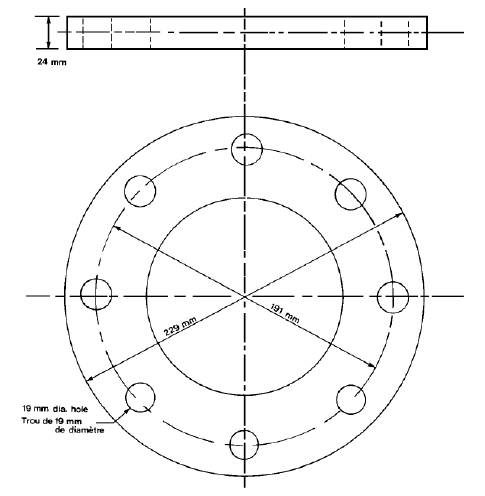
10.1.7. 燃油的储量
在船上有足够的燃油,使得该船舶能够
① 完成在这些区域内的预计航程并离开这些区域,或者
② 抵达在其预计航行的区域内的任何加油地点;
北冰洋级船舶除了上述①、②规定,在船上还有供本船使用30天的燃油储备;
10.1.8. 淡水的储量;
在预计的航程中,船上有足够的淡水或能够生产足够数量淡水的设备,使得该船舶能够
① 完成在这些区域内的预计航程并离开这些区域,或者
② 抵达在其预计航行的区域内的任何可以获得淡水的地点。
北冰洋级船舶除了上述①、②规定,在船上还有供本船使用30天的淡水储备或者能够生产供本船使用30天淡水的设备;
10.1.9. 冰水引航员的要求;
(a) 能遵照依据《加拿大航运法案》制订的规则、合格地充当船长或者舱面值班负责人员来行事;以及
(b) 已经在船上的船长岗位或者舱面值班负责人员岗位服役至少50天,其中30天必须在北冰洋水域服役,期间其船舶在冰水状态航行,要求有破冰船的帮助或者进行机动动作以避免冰块聚集而危害船舶。
10.1.10. 生活污水和油污水的排放;满足MARPOL的前提下,生活污水可以排放,油污水禁止排放;
10.1.11. 北冰洋防污染证书;该证书不是强制性的,非加拿大船舶,由检验员、认可船级社经检查签发ASPPR的符合证明;
10.2 我社应船公司申请对CCS级船舶签发北极水域防污染要求的符合声明的有关规定
10.2.1. 应船公司申请,对CCS级船舶进行签发北极防污染符合证明时,验船师在对以下项目进行检查、 验证满意情况下,使用社徽证书纸签发北极防污染符合证明(Form SOC(CAN-APP)),检验种类为NS_ADS(CAN-APP):
10.2.2. 根据船舶冰区加强的标志,明确船舶类型;CCS的各种冰区加强标志所对应的船舶类型,见上述 10.1.3.2条;
10.2.3. 核查证书:确认船舶《入级证书》、《客船安全证书》(如适用时)、《货舱构造安全证书》、《货船设备安全证书》、《国际载重线证书》的有效性。
10.2.4. 核查加油站的布置以及加油站法兰的规格;
10.2.1.1. 核查燃油的储备;
10.2.1.2. 核查淡水的储备;
10.2.5. 船上配员的核查:船上应配有冰水引航员,除非船舶在无冰水面中航行,可以没有冰水领航员。“无冰水面”的定义见《北冰洋冰区航运系统标准》,该标准由加拿大交通部船舶安全部门于1996年 6月发布,不时经过修正。
10.2.6. 载油量453m3 及以上的B型船舶,即:CSA Ice B1,每年自8月1日始至8月24日止的期限内,在第六区域航行(该区对B型船可以航行的时间段为:每年的8月25日至9月30日)的附加要求:
10.2.7. 有破冰船担任护航任务;
10.2.8. 如果该船舶运载的货物是油类,有破冰船护航,且该破冰船上具备对漏油进行立即反应的措施。
10.2.9. 资料核查,核查船舶已配备《北极水域防污染法案》,《北冰洋船舶防污染规则》及附件,船长对上述法案及规则包括附件的内容足够熟悉。
10.2.10. 北极防污染符合证明的有效期,北极防污染符合证明有效期最长一年,不超过签发之日后的首个3月31日,如签发日期为2011年4月1日,则有效期最长不超过2012年3月31日。注:在此期间其它证书应有效。
10.2.11. 北极防污染符合证明的失效,如果10.2.1.2所述船舶证书失效,则北极防污染符合证明同时失效。
10.2.12. 符合证明格式见附录
10.2.13. 符合证明的填写说明:
10.2.14. 对于A、B、C、D型船舶,其船舶首、尾最大/最小吃水的数值可以从批准的冰区加强结构图等有关图纸中获得,如果船上资料不全,也可以按照《钢质海船入级规则》的相应要求确定,当现场确定相关数据有困难时,需与审图中心联系。
10.2.15. 对于E型船舶,其船舶首、尾最大/最小吃水的数值可以从批准的“完工稳性计算书”或“完工 装载手册”等有关图纸中获得。
10.3 参考信息
本段涉及的加拿大政府对北极水域防污染规定及其相关最新要求,请到以下官方网站查询、下载:http://laws-lois.justice.gc.ca/eng/acts/A-12/index.html
美国环保署(EPA)最新发布了船舶通用许可(Final 2013 VGP),自2013年12月19日生效,并取代2008VGP。根据EPA 2013 VGP,2013年12月19日及以后所有进入美国水域(沿海3海里)的船舶,除非技术上不可行,在船舶的油水界面上必须使用环保润滑油(EAL)。
环保润滑油:系指满足2013VGP附录A定义的“可生物降解”、“最低限度毒性”和“不具有生物累积性”。
油水界面:指根据2013 VGP Fact Sheet Sec. 4.4.9,这些油水界面包括但不限于:可调距桨,推进器液压油及其他油水界面(明轮,艉轴管,螺旋桨轴承,减摇装置,舵承,全回转推进器,吊舱式推进器,浸没的钢丝绳和机械设备)。
技术不可行:指没有经认可的满足设备制造商规格书要求的EAL产品(如油封)可供使用;需预润滑的设备(如钢丝绳)没有可用的EAL替代产品;船舶航经港口内无法获得满足制造商规格书要求的EAL产品;须等到船舶下次进干坞才能更换或使用EAL产品。
新船:对于2013 VGP Fact Sheet Sec. 4.4.9而言,新船为2013年12月19日及以后安放龙骨或出于类似建造阶段的船舶。
11.3.1申请
11.3.1.1该检验应为依据船东申请而进行的鉴证检验。
11.3.2 检验的种类
11.3.2.1检验种类为鉴证检验(NS_ADS(US-EAL))。
11.3.3检验范围
11.3.3.1 使用环保润滑油是技术不可行。
11.3.3.2 使用环保润滑油应符合2013VGP Fact Sheet Sce.4.4.9 以及2013VGP附录A所定义的“环保润滑油”的要求。
11.3.3.3 使用替代的密封系统(如“空气密封”或带空腔的双层密封”代替EALs时,替代的密封系统需经本社产品型式认可。
11.3.4检验和检验报告
11.3.4.1验船师完成检验后应签发符合证明Form SOC(US-EAL)(Ver1.0 201501)(参见SSMIS模版)
11.3.4.2应船东/船公司的申请,对CCS级船舶进行环保润滑油使用情况的进行签证检验时,验船师应对以下项目进行检查、验证满意情况下,使用社徽证书纸签发符合证明Form SOC(US-EAL)(Ver1.0 201501)。
1)应船东申请,按2013VGP Fact Sheet Sec.4.4.9中关于“技术不可行”的要求签发符合证明时,应在符合证明Form SOC(US-EAL)(Ver1.0 201501)的条款1~条款4中选取适用的选项。
a.如没有经认可的满足设备制造商规格书要求的EAL产品可供使用,验船师应验证设备制造商提交的声明,该声明应包括设备名称、设备型号及不能满足设备制造商规格书要求的支持性材料。在RA报告中描述“In the case that no EAL products are approved for use in a given application that meet manufacturer specifications for that equipment, supporting documents should be provided by the manufacturer and maintained on board. Equipment Name and the manufacturer ”
b.如需要预润滑的设备没有可用的EAL替代产品,验船师应验证预润滑设备制造商提交的声明,该声明应包括预润滑设备名称、设备型号及无可用的EAL替代产品的支持性材料。在RA报告中描述“In the case that pre-purchased lubricated products have no available alternatives manufactured with EALs, supporting documents should be provided by the manufacturer and maintained on board. Equipment Name and the manufacturer ”
c.如船舶航经港口内无法获得满足制造商规格书要求的EAL产品,验船师应验证船东/船公司提交的声明,该声明应包括船舶航行路线、制造商规格书的要求及EAL无法购买的理由。在RA报告中描述“In the case that products meeting manufacturer specifications are not available within any port in which the vessel calls, supporting documents should be provided by the ship owner/operator and maintained on board. Equipment Name and the manufacturer ”
d.如船舶下次进干坞才能更换和使用EAL产品,验船师应查阅上次进坞日期,本条款适用于2013年12月19之前进干坞的船舶。在RA报告中描述“In the case that change over and use of an EAL must wait until the vessel’s next drydocking, documentation should be provided by the ship owner/operator and maintained on board. Date of last drydocking ,Date of next drydocking ”
验船师应提醒船东将上述提及的声明及支持性材料保存在船上和将技术不可行的理由和非环保润滑油的使用情况及部位记录在年度报告中(见2013 VGP Fact Sheet Sec. 4.4.9)。在船舶执行“技术不可行”要求时,船东需将下列操作事项纳入船舶管理体系中:
可调距桨、全回转推进器、吊舱式推进器、舵承及其他油水界面上的密封装置应保持在良好操作状态以使液压油或其他油类的渗漏减至最低。船舶的船东或经营人不得自任何油水界面排放有害数量的油类。如可行,应在干坞内对船舶可调距桨、推进器和其他油水界面上的装置进行维护保养。
当船舶不在干坞时应尽可能少地对艉轴管密封装置进行维护保养。如必须对艉轴管或其他油水界面上的装置进行维护保养或应急修理,且有可能排放出有害数量的油类,应使用合适的泄露处置设备(如围油栏)以控制溢油。应有直接通道至泄露处置设备以清除溢油。
在确保安全情况下,对拟浸没水中的钢索或机械设备涂抹润滑油,入水前应清除过量的润滑油。
2)应船东申请,按2013 VGP使用环保润滑油的要求签发符合声明,验船师应检查下列文件并保存在船上:环保润滑油的Material Safety Data Sheets (MSDS);环保润滑油产品制造商提供的符合2013VGP要求的符合声明;使用环保润滑油设备的制造商提供的符合声明,该声明应说明该设备制造商的设备已经与符合2013VGP要求的环保润滑油进行了匹配性试验,试验结果符合设备制造商的要求;环保润滑油应获得下述的认证标识,EPA认为已经符合2013VGP关于环保润滑油的定义,例如German Blue Angel(蓝天使), European Eco-label(欧洲之花), Nordic Swan(北欧天鹅), the Swedish Standards SS 155434 and 155470(瑞典标准)Convention for the Protection of the Marine Environment of the North-East Atlantic (OSPAR)requirements )(《东北大西洋海洋环境保护公约》(OSPAR)要求), and EPA’s Design for the Environment (DfE) (EPA的环境设计项目);
“新船”完成环保润滑油的检验应在RA中描述“环保润滑油型号 is environmentally acceptable lubricants as defined in Appendix A of 2013 Vessel General Permit upon reviewing the statement issued by 环保润滑油生产商 。The currently used
设备名称 device is compatible with 环保润滑油型号 upon reviewing the statement issued by 设备制造商 on 月/日/年”。
“现有船”完成环保润滑油的检验应在RA中描述“The oil has been replaced with is environmentally acceptable lubricant as defined in Appendix A of the 2013 Vessel General Permit upon reviewing the statement issued by on 月/日/年”.The currently used 设备名称 device is compatible with环保润滑油型号 upon reviewing the statement issued by 设备制造商on 月/日/年”.
3)空气密封系统的使用情况是CCS认可的空气密封系统尚未完成EPA要求的型式试验项目,尚不能签发,待完成EPA要求的型式试验后对须知进行修改。
4)EAL的使用不代表可以随意排放有害数量的润滑油,排放量任何时候不能超过40CFR所规定的范围且不能影响水质和不形成油迹。
11.3.4.3签发“符合证明”的注意事项
1)新船几乎不存在“技术不可行”的情况,理由是“新船”在设计、选型阶段即可选择符合EALs要求的产品,或者类似产品,另外还可以选择诸如海水润滑系统(Seawater Based systems)和其他的替代产品来规避环保润滑油油的要求。所以新船签发“符合证明”时,条款1~条款4应划不适用。
2)现有船更换并使用环保润滑油时,应注意环保润滑油对与其接触的材料的影响,例如艉轴管润滑油更换为环保润滑油,需要核实艉轴管密封装置的密封材料是否适应环保润滑油的使用要求,如不适应应更换。
3)如签发符合2013 VGP环保润滑油的使用的符合证明,验船师应核实所有的油水界面设备都已经满足2013VGP关于环保润滑油的使用要求。
11.3.4.4 检验报告按CCS程序、须知要求报送总部。
N12 签发苏伊士运河当局《航行规则》设备要求的符合性声明
12.1 苏伊士运河当局规定所有通过苏伊士运河的船舶,除应满足SOLAS公约、IMDG规则(载运危险货物的船舶)、MARPOL 73/78公约、COLREG规则以及所有埃及政府颁布的法律、法令和规定外,还应满足其《航行规则》(http://www.suezcanal.gov.eg
/NR.aspx)的要求。
12.2 通过苏伊士运河船舶的设备要求
12.2.1 舱室与处所
12.2.1.1
船舶应为引航员提供适当的住处(高级船员级别)。
根据航行规则第42.1条,当在苦湖锚泊或在运河沿岸的停泊处系泊时,应为引航员提供适当的住处(高级船员级别)。万一无可用的适当住处,船舶将额外为每个临时雇聘的引航员支付1000美元的报酬。
12.2.1.2
船舶在通过苏伊士运河期间应为3-6名带缆工人和2名操作探照灯的岸上电工提供有遮蔽的处所。
根据航行规则第42.2条,在通过苏伊士运河期间,应为带缆工人(根据船舶尺度确定3-6名)和2名操作探照灯的岸上电工提供有遮蔽的处所。关于带缆工人的人数,可依据航行规则第20条来确定:对于5000苏伊士运河总吨位(SC.G.T)及以下的船舶,要求3人;对于5000SC.G.T以上的船舶,要求6人。
航行规则中并未对遮蔽处所进行定义及解释,可以理解为只要船舶在其露天甲板上设有这样一块其空间可容纳3至6名带缆工和2名岸上电工并设有雨篷可为其遮阳避雨的处所即可。
一般通过苏伊士运河船舶并没有特别给带缆工人和岸上电工提供有遮蔽的处所。一般船舶主甲板上均有空余的房间,当船靠码头时这些房间可提供给诸如理货人员、码头工人等休息使用。因此,可以认为这些房间能满足运河规则中的“遮蔽处所”的要求。
12.2.2
系泊和锚泊
12.2.2.1 船舶必须配备能够起吊4吨重的系泊船(包括3名船员重量)的起重装置。
根据航行规则第20.5条,船舶必须安装维护良好的起重装置,该起重装置能够吊落4吨重的系泊船(包括3名船员重量)。系泊船的操作必须安全,远离船舶推进器。关于系泊船的租用、替代、操纵以及额外配备等,可参考航行规则第20条。
12.2.2.2 船舶必须配备至少6根可浮式系泊索。对于配有牵引钢丝绳系泊索的船舶,该数量可减为4根。对于油船、LPG、LNG以及载运易燃物质的船舶,禁止使用可能产生火花的绳索。
根据航行规则第19.1条,船舶在甲板上适当位置必须配备至少6根合适尺寸的具有索端眼环的柔性可浮式系泊索,并保持良好状态,以供任何紧急情况下使用。所有的布置应能快速操作。同时,根据航行规则第19.2条,对于配有牵引钢丝绳系泊索的船舶,可浮式系泊索的数量可减为4根。对于油船、LPG、LNG以及载运易燃物质的船舶,绝对禁止使用在操作时可能产生火花的任何绳索。此外,关于绳索的操作和钢丝绳的规格尺寸等相关要求,可进一步参考航行规则第19.3条。
注意到,本社规范中建议舾装数EN>205时,系泊索数量不少于4根;EN>2530时,系泊索数量不少于6根。
12.2.2.3 所有船舶应配备两只经船级社认可的锚并布置在防撞舱壁之前。对于小于1500SC.G.T
的船舶,必须在首部配备一只工作锚。
根据航行规则第23.1条,所有通过运河的船舶都应配备两只认可的锚并布置在防撞舱壁之前。每只锚都应备有独立的锚链或钢丝绳,并能够通过重力释放,也能通过锚机或绞盘进行提升。同时,根据航行规则第23.2条,作为替代,小于1500
SC.G.T总吨的船舶必须在首部配备一只工作的锚。
注意到,根据本社《钢质海船入级规范》第2篇第3章第2节的规定,所有船舶的首锚至少为2个。因此,满足本社规范的船舶,已经满足上述航行规则的要求。
12.2.3 消防设备
所有船舶应配有2根防火钢丝索。
根据航行规则第61.3条,在进入运河之前,所有船舶应备有2根防火钢丝索,分别系牢在船首尾两端,并垂挂在舷外,以备应急时使用。也可参见航行规则第37.3条和第19.3(c)条。
12.2.4
引航员登离船装置
应配备经船级社认可的舷梯。
根据航行规则第24.1.1条,在运河外的北部或南部之外的锚泊区,引航员可利用引航员软梯上下船。软梯应在其位置上保护以使得每级踏板稳固地紧靠在船舷,确保引航员能安全登船和离船。当海平面至登船点距离超过12英尺(3.65米)时,从引航员软梯登离船舶时应利用舷梯或其他类似安全方便的工具。又根据航行规则第24.2.1条,在运河港口和湖泊内登离船应使用舷梯。
12.2.5 照明器具
12.2.5.1
探照灯
12.2.5.1.1
船舶应配备经船级社认可并发证的探照灯,其应满足航行规则的相关要求。
根据航行规则第28.2.10条,探照灯必须有型式试验证书。该证书由船级社签发,并证明能满足航行规则中规定的规格要求。测试应包括亮度测试且要符合相关说明。证书原件呈交运河官方,并经苏伊士运河管理当局(SCA)检查官测试后,探照灯才能被接受。
该探照灯应位于船舶中轴线上并安置在船首,同时必须满足航行规则第28.2条中所规定的规格要求,包括照射距离、功率、材料、水密性、散热等。
船舶可从当地公司租用便携式探照灯,但LPG、LNG以及直接来自海上进入运河的船舶必须自身装有探照灯。对于自身装有探照灯的船舶,在过河期间探照灯应由两个岸上电工操作。
对于不符合上述要求的情况以及相关免除信息,请进一步可参考航行规则第28条。
12.2.5.1.2
探照灯的电缆和电气连接件都必须永久地固定好、绝缘和气密。在电缆末端,靠近探照灯处,应安装固定气密防爆插座。
根据航行规则第28.3条,对于所有载运石油、LNG或可燃物的船舶以及有气体挥发的船舶,用于探照灯的电缆装置和所有的与其相连的电气连接件都必须永久地固定好、绝缘和气密。在电缆末端,靠近探照灯处,应安装固定气密防爆插座。
12.2.5.1.3
发电机的数量及其各自的功率输出应能保证:停止其中一台发电机时,不影响探照灯正常工作。
根据航行规则第28.4条,在电力推进或者具有电动装置(舵机、绞缆机等)的船舶上,发电机的数量及其各自的功率输出必须充足以保证:停止其中一台发电机时,不影响探照灯正常工作。但船上为探照灯单独设有独立的发电机和线路则可除外。
12.2.5.2
甲板灯
船舶应安装甲板灯,其在360
度水平范围之内照射距离至少200m。
根据航行规则第29条,甲板灯在360度水平范围之内至少200m(大概650英尺)要有良好照明,且是防爆类型。
12.2.5.3
翼桥探照灯
船舶应在每舷安装翼桥探照灯,其照度约4勒克斯且最小照射距离为200m。
根据航行规则第30条,在通过运河和系泊期间,必须在驾驶台每侧安装翼桥探照灯以清楚地照亮运河两岸。它们必须要有以下特性:其功率在大气传递因数T=0.74时,照度约4勒克斯且最小照射距离为200m的防爆类型。
12.2.5.4
烟囱照亮
烟囱必须被照亮,以便夜间识别船舶。
根据航行规则第31条,烟囱必须被照亮,以便夜间识别船舶。
12.2.6
航行设备
舵角指示器和主机转速指示器应在驾驶台合理放置和照明,以让引航员容易察看。
根据航行规则第22条,驾驶台应安装舵角指示器和主机转速指示器,其应合理放置和照明以让引航员容易察看。关于两者有缺陷时的情况,请进一步参考该条要求。
注意到,SOLAS公约第V/19.2.5.4条规定舵、螺旋桨、推力、螺距和工作模式指示器应在指挥驾驶位置清晰可读。因此,满足SOLAS公约要求的船舶,一般都认为满足该条要求。
12.2.7 信号设备
12.2.7.1
红色苏伊士运河尾灯可用。
根据航行规则第92.B(13)条,船舶在运河内系泊时,应熄灭两盏白灯,并在尾部一直显示一盏红灯,直到实际开航为止。该要求和COLREG显示锚灯的要求有明显差别。
12.2.7.2
船舶应配备通过运河所要求的号灯。
航行规则第92.B条规定了船舶在港口和运河内所要显示的特殊号灯。船舶通过显示不同的号灯组合,表达船舶的意图,如申请引航员、申请免检、申请拖船、无系泊船、无探照灯、系泊等等各种情况。船舶所配备的号灯应满足航行规则第92.B条的要求。
12.2.8
吃水标志
所有船舶应在船首、船中(包括干舷和甲板线)和船尾(艉柱或者舵柱处)堪划吃水标志。
根据航行规则第35条,所有船舶应根据载重线公约在船首、船中(包括干舷和甲板线)和船尾(艉柱或者舵柱处)堪划吃水标志。注意到,SOLAS公约第II-1章第5条规定了吃水标志,仅要求在船首和船尾标示,苏伊士运河航行规则要求在船中也要标示,船尾的标示位置则明确为艉柱或者舵柱处。
12.2.9 集装箱船的附加要求
装载不同尺寸集装箱的集装箱船必须配备独立的吊架。
根据航行规则第21条,建议集装箱配备独立的吊架(吊索)在必要时帮助装卸集装箱。装载不同尺寸集装箱的集装箱船必须配备独立的吊架。
12.3
签发符合性声明及检验报告
12.3.1
涉及《航行规则》设备要求的图纸应经过审图中心审批,现场验船师根据船上的具体布置、批准的图纸和试验结果进行船舶满足苏伊士运河当局《航行规则》设备要求的符合性检验,合格后使用社徽证书纸签发“苏伊士运河当局《航行规则》符合声明”(Form
SOC(SCA-RN))以及检验报告(Form
RNc),检验种类为鉴证检验NS_ADS(SCA-RN)。
12.3.2
符合声明不代表苏伊士运河当局签发,仅表明符合本社对其航行规则有关通过苏伊士运河所要求的设备的理解,并不排除苏伊士运河当局在船舶通过苏伊士运河时提出附加检验或要求提供附加证据的可能性。
12.4
说明
苏伊士运河当局《航行规则》可通过苏伊士运河管理局官方网站(http://www.suezcanal.gov.eg
/NR.aspx获得,验船师应注意该规则的可能变化。
N13 中国水域船舶排放控制区(2015年技术通告第39号总第200号)
中国交通运输部于2015年12月4日发布了“珠三角、长三角、环渤海(京津冀)水域船舶排放控制区实施方案”,该方案将于2016年1月1日生效。
1、适用船舶
适用于在排放控制区内航行、停泊、作业的船舶,军用船舶、体育运动船艇和渔业船舶除外。
2、排放控制区
排放控制区实施方案定义了3个排放控制区:珠三角、长三角、环渤海水域。
3、排放控制区排放控制要求
对于硫氧化物应参照表1要求执行:
表1:硫氧化物排放控制时间表
|
日期 |
燃油硫含量 (m/m) |
适用区域 |
时段 |
|
2016.01.01——
2016.12.31 |
≤0.5%,或等效替代措施 |
有条件的港口(自愿) |
靠岸停泊期间(靠港后的一小时和离港前的一小时除外,下同) |
|
≤3.5% |
排放控制区内除有条件的港口之外的其他区域(强制) |
所有时段 |
|
2017.01.01——
2017.12.31 |
≤0.5%,或等效替代措施 |
核心港口(强制) |
靠岸停泊期间 |
|
≤0.5%,或等效替代措施 |
核心港口之外的其他有条件的港口(自愿) |
靠岸停泊期间 |
|
≤3.5% |
排放控制区内除核心港口、有条件的港口之外的其他区域(强制) |
所有时段 |
|
2018.01.01——
2018.12.31 |
≤0.5%,或等效替代措施 |
所有港口(强制) |
靠岸停泊期间 |
|
≤3.5% |
排放控制区内除所有港口之外的其他区域(强制) |
所有时段 |
|
2019.01.01——
2019.12.31 |
≤0.5%,或等效替代措施 |
排放控制区(强制) |
所有时段 |
|
自2020.01.01起 |
≤0.1%,或等效替代措施 |
排放控制区;
扩大排放控制区地围;
其他进一步举措 |
2019年12月31日前完成评估以便确定是否采取进一步行动 |
* 港口当局可能提前发布通告(尤其是那些核心港口,如上海)。
** 替代措施包括使用岸电、清洁能源如LNG、尾气后处理系统。
*** 以上内容若与交通运输部发布的实施方案中文版和正式发布的英文版有出入,应以交通运输部官方版本为准。
4、措施和建议
4.1、海事机关可能制定相关实施程序以便加强对适用船舶的检查以验证其符合性,为此建议适用船舶应建立并实施相关程序,如培训程序、加油程序、燃油切换程序、操作程序,相关支持文件如燃油供应单、油类记录簿、日志等以及燃油样品应保存在船上。
4.2、我社就低硫燃油的要求先后发布了2014年总第160号技术通告、2010年总第17号通函及“船舶使用低硫燃油指南”等文件,对在排放控制区内使用的燃油,如有需要,船公司等相关方可利用这些文件适当地开展燃油使用的评估、分析、设计、改造等工作,并根据船公司要求提供相应的图纸资料审批、检验和签发证明文件,具体操作可参考“III N5欧盟对船舶硫氧化物排放控制要求”执行。